BCM MX525DC Manuale utente
- Categoria
- Schede madri
- Tipo
- Manuale utente
Questo manuale è adatto anche per

WWW.BCMCOM.COM
User’s Manual
MX525D/DC
Industrial Mini ITX Motherboard

■ Preface
ii
Copyright Notice
The material in this document is the intellectual property of
BCM Advanced
BCM Advanced
Research
Research. We take every care in the preparation of this document, but no
guarantee is given as to the correctness of its contents. Our products are under
continual improvement and we reserve the right to make changes without notice.
Trademarks
All trademarks are the properties of their respective owners.
■ BCM
®
is registered trademark of BCM Advanced Research.
■ NVIDIA
®
is registered trademark of NVIDIA Corporation.
■ ATI
®
is registered trademark of ATI Technologies, Inc.
■ AMD
®
is registered trademarks of AMD Corporation.
■ Intel
®
is registered trademarks of Intel Corporation.
■ Windows
®
is registered trademarks of Microsoft Corporation.
■ AMI
®
is registered trademark of Advanced Micro Devices, Inc.
■ Award
®
is a registered trademark of Phoenix Technologies Ltd.
■ Sound Blaster
®
is registered trademark of Creative Technology Ltd.
■ Realtek
®
is registered trademark of Realtek Semiconductor Corporation.
■ JMicron
®
is registered trademark of JMicron Technology Corporation.
■ Netware
®
is a registered trademark of Novell, Inc.
Revision History
Revision
Revision
Revision History
Revision History
Date
Date
V1.1 08/31/2011
Technical Support
If a problem arises with your system and no solution can be obtained from
the user’s manual, please contact your place of purchase or local distributor.
Alternatively, please try the following help resources for further guidance.
■ Visit the BCM website for technical guide, BIOS updates, driver updates,
and other information:
http://www.bcmcom.com/bcm_support_drivers.htm
http://www.bcmcom.com/bcm_support_drivers.htm
◙ Contact our technical staff at:
http://www.bcmcom.com/bcm_inquiries_
http://www.bcmcom.com/bcm_inquiries_
techSupport.htm
techSupport.htm

iii
MX525D / MX525DC
Safety Instructions
■ Always read the safety instructions carefully.
■ Keep this User’s Manual for future reference.
■ Keep this equipment away from humidity.
■ Lay this equipment on a reliable fl at surface before setting it up.
■ The openings on the enclosure are for air convection hence protects the
equipment from overheating. DO NOT COVER THE OPENINGS.
■ Make sure the voltage of the power source and adjust properly 110/220V
before connecting the equipment to the power inlet.
■ Place the power cord such a way that people can not step on it. Do not
place anything over the power cord.
■ Always Unplug the Power Cord before inserting any add-on card or module.
■ All cautions and warnings on the equipment should be noted.
■ Never pour any liquid into the opening that could damage or cause
electrical shock.
■ If any of the following situations arises, get the equipment checked by
service personnel:
◯ The power cord or plug is damaged.
◯ Liquid has penetrated into the equipment.
◯ The equipment has been exposed to moisture.
◯ The equipment does not work well or you can not get it work according
to User’s Manual.
◯ The equipment has dropped and damaged.
◯ The equipment has obvious sign of breakage.
■ DO NOT LEAVE THIS EQUIPMENT IN AN ENVIRONMENT
UNCONDITIONED, STORAGE TEMPERATURE ABOVE 60
o
C (140
o
F), IT
MAY DAMAGE THE EQUIPMENT.
CAUTION
CAUTION: Danger of explosion if battery is incorrectly replaced. Replace only
with the same or equivalent type recommended by the manufacturer.
警告使用者:
這是甲類資訊產品,在居住的環境中使用時,可能會造成無線電干擾,在這種情
況下,使用者會被要求採取某些適當的對策。
廢電池請回收
For better environmental protection, waste batteries should be
collected separately for recycling or special disposal.

■ Preface
iv
FCC-B Radio Frequency Interference Statement
This equipment has been tested and
found to comply with the limits for a Class
B digital device, pursuant to Part 15 of the
FCC Rules. These limits are designed
to provide reasonable protection against
harmful interference in a residential installation. This equipment generates, uses and
can radiate radio frequency energy and, if not installed and used in accordance with
the instructions, may cause harmful interference to radio communications. However,
there is no guarantee that interference will not occur in a particular installation. If this
equipment does cause harmful interference to radio or television reception, which
can be determined by turning the equipment off and on, the user is encouraged to try
to correct the interference by one or more of the measures listed below.
◯ Reorient or relocate the receiving antenna.
◯ Increase the separation between the equipment and receiver.
◯ Connect the equipment into an outlet on a circuit different from that to
which the receiver is connected.
◯ Consult the dealer or an experienced radio/television technician for help.
Notice 1
The changes or modifi cations not expressly approved by the party responsible for
compliance could void the user’s authority to operate the equipment.
Notice 2
Shielded interface cables and A.C. power cord, if any, must be used in order to
comply with the emission limits.
VOIR LA NOTICE D’INSTALLATION AVANT DE RACCORDER AU RESEAU.
This device complies with Part 15 of the FCC Rules. Operation is subject to the
following two conditions:
1) this device may not cause harmful interference, and
2) this device must accept any interference received, including interference that
may cause undesired operation.
BCM Advanced Research
MX525D / MX525DC

v
MX525D / MX525DC
WEEE (Waste Electrical and Electronic Equipment) Statement
ENGLISH
To protect the global environment and as an environmentalist, BCM must re-
mind you that:
Under the European Union (“EU”) Directive on Waste Electrical and Electronic
Equipment, Directive 2002/96/EC, which takes effect on August 13, 2005,
products of “electrical and electronic equipment” cannot be discarded as municipal waste
anymore and manufacturers of covered electronic equipment will be obligated to take back
such products at the end of their useful life. BCM will comply with the product take back
requirements at the end of life of BCM-branded products that are sold into the EU. You can
return these products to local collection points.
DEUTSCH
Hinweis von BCM zur Erhaltung und Schutz unserer Umwelt
Gemäß der Richtlinie 2002/96/EG über Elektro- und Elektronik-Altgeräte dürfen Elektro-
und Elektronik-Altgeräte nicht mehr als kommunale Abfälle entsorgt werden. BCM hat
europaweit verschiedene Sammel- und Recyclingunternehmen beauftragt, die in die Eu-
ropäische Union in Verkehr gebrachten Produkte, am Ende seines Lebenszyklus zurück-
zunehmen. Bitte entsorgen Sie dieses Produkt zum gegebenen Zeitpunkt ausschliesslich
an einer lokalen Altgerätesammelstelle in Ihrer Nähe.
FRANÇAIS
En tant qu’écologiste et afi n de protéger l’environnement, BCM tient à rappeler ceci:
Au sujet de la directive européenne (EU) relative aux déchets des équipement électriques
et électroniques, directive 2002/96/EC, prenant effet le 13 août 2005, que les produits
électriques et électroniques ne peuvent être déposés dans les décharges ou tout simple-
ment mis à la poubelle. Les fabricants de ces équipements seront obligés de récupérer
certains produits en fi n de vie. BCM prendra en compte cette exigence relative au retour
des produits en fi n de vie au sein de la communauté européenne. Par conséquent vous
pouvez retourner localement ces matériels dans les points de collecte.
РУССКИЙ
Компания BCM предпринимает активные действия по защите окружающей среды,
поэтому напоминаем вам, что:
В соответствии с директивой Европейского Союза (ЕС) по предотвращению
загрязнения окружающей среды использованным электрическим и электронным
оборудованием (директива WEEE 2002/96/EC), вступающей в силу 13 августа 2005
года, изделия, относящиеся к электрическому и электронному оборудованию, не могут
рассматриваться как бытовой мусор, поэтому производители вышеперечисленного
электронного оборудования обязаны принимать его для переработки по окончании
срока службы. BCM обязуется соблюдать требования по приему продукции,
проданной под маркой BCM на территории EC, в переработку по окончании срока
службы. Вы можете вернуть эти изделия в специализированные пункты приема.

■ Preface
vi
ESPAÑOL
BCM como empresa comprometida con la protección del medio ambiente, recomienda:
Bajo la directiva 2002/96/EC de la Unión Europea en materia de desechos y/o equipos
electrónicos, con fecha de rigor desde el 13 de agosto de 2005, los productos clasifi cados
como “eléctricos y equipos electrónicos” no pueden ser depositados en los contenedores
habituales de su municipio, los fabricantes de equipos electrónicos, están obligados a
hacerse cargo de dichos productos al termino de su período de vida. BCM estará com-
prometido con los términos de recogida de sus productos vendidos en la Unión Europea
al fi nal de su periodo de vida. Usted debe depositar estos productos en el punto limpio
establecido por el ayuntamiento de su localidad o entregar a una empresa autorizada para
la recogida de estos residuos.
NEDERLANDS
Om het milieu te beschermen, wil BCM u eraan herinneren dat:
De richtlijn van de Europese Unie (EU) met betrekking tot Vervuiling van Electrische en
Electronische producten (2002/96/EC), die op 13 Augustus 2005 in zal gaan kunnen niet
meer beschouwd worden als vervuiling. Fabrikanten van dit soort producten worden verpli-
cht om producten retour te nemen aan het eind van hun levenscyclus. BCM zal overeenk-
omstig de richtlijn handelen voor de producten die de merknaam BCM dragen en verkocht
zijn in de EU. Deze goederen kunnen geretourneerd worden op lokale inzamelingspunten.
SRPSKI
Da bi zaštitili prirodnu sredinu, i kao preduzeće koje vodi računa o okolini i prirodnoj sredini,
BCM mora da vas podesti da:
Po Direktivi Evropske unije (“EU”) o odbačenoj ekektronskoj i električnoj opremi, Direktiva
2002/96/EC, koja stupa na snagu od 13. Avgusta 2005, proizvodi koji spadaju pod “elek-
tronsku i električnu opremu” ne mogu više biti odbačeni kao običan otpad i proizvođači ove
opreme biće prinuđeni da uzmu natrag ove proizvode na kraju njihovog uobičajenog veka
trajanja. BCM će poštovati zahtev o preuzimanju ovakvih proizvoda kojima je istekao vek
trajanja, koji imaju BCM oznaku i koji su prodati u EU. Ove proizvode možete vratiti na
lokalnim mestima za prikupljanje.
POLSKI
Aby chronić nasze środowisko naturalne oraz jako fi rma dbająca o ekologię, BCM przy-
pomina, że:
Zgodnie z Dyrektywą Unii Europejskiej (“UE”) dotyczącą odpadów produktów elektryc-
znych i elektronicznych (Dyrektywa 2002/96/EC), która wchodzi w życie 13 sierpnia 2005,
tzw. “produkty oraz wyposażenie elektryczne i elektroniczne “ nie mogą być traktowane
jako śmieci komunalne, tak więc producenci tych produktów będą zobowiązani do odbi-
erania ich w momencie gdy produkt jest wycofywany z użycia. BCM wypełni wymagania
UE, przyjmując produkty (sprzedawane na terenie Unii Europejskiej) wycofywane z użycia.
Produkty BCM będzie można zwracać w wyznaczonych punktach zbiorczych.

vii
MX525D / MX525DC
TÜRKÇE
Çevreci özelliğiyle bilinen BCM dünyada çevreyi korumak için hatırlatır:
Avrupa Birliği (AB) Kararnamesi Elektrik ve Elektronik Malzeme Atığı, 2002/96/EC Kara-
rnamesi altında 13 Ağustos 2005 tarihinden itibaren geçerli olmak üzere, elektrikli ve elek-
tronik malzemeler diğer atıklar gibi çöpe atılamayacak ve bu elektonik cihazların üreti-
cileri, cihazların kullanım süreleri bittikten sonra ürünleri geri toplamakla yükümlü olacaktır.
Avrupa Birliği’ne satılan BCM markalı ürünlerin kullanım süreleri bittiğinde BCM ürünlerin
geri alınması isteği ile işbirliği içerisinde olacaktır. Ürünlerinizi yerel toplama noktalarına
bırakabilirsiniz.
ČESKY
Záleží nám na ochraně životního prostředí - společnost BCM upozorňuje:
Podle směrnice Evropské unie (“EU”) o likvidaci elektrických a elektronických výrobků
2002/96/EC platné od 13. srpna 2005 je zakázáno likvidovat “elektrické a elektronické
výrobky” v běžném komunálním odpadu a výrobci elektronických výrobků, na které se
tato směrnice vztahuje, budou povinni odebírat takové výrobky zpět po skončení je-
jich životnosti. Společnost BCM splní požadavky na odebírání výrobků značky BCM,
prodávaných v zemích EU, po skončení jejich životnosti. Tyto výrobky můžete odevzdat
v místních sběrnách.
MAGYAR
Annak érdekében, hogy környezetünket megvédjük, illetve környezetvédőként fellépve az
BCM emlékezteti Önt, hogy:
Az Európai Unió („EU”) 2005. augusztus 13-án hatályba lépő, az elektromos és elek-
tronikus berendezések hulladékairól szóló 2002/96/EK irányelve szerint az elektromos és
elektronikus berendezések többé nem kezelhetőek lakossági hulladékként, és az ilyen
elektronikus berendezések gyártói kötelessé válnak az ilyen termékek visszavételére
azok hasznos élettartama végén. Az BCM betartja a termékvisszavétellel kapcsolatos
követelményeket az BCM márkanév alatt az EU-n belül értékesített termékek esetében,
azok élettartamának végén. Az ilyen termékeket a legközelebbi gyűjtőhelyre viheti.
ITALIANO
Per proteggere l’ambiente, BCM, da sempre amica della natura, ti ricorda che:
In base alla Direttiva dell’Unione Europea (EU) sullo Smaltimento dei Materiali Elettrici ed
Elettronici, Direttiva 2002/96/EC in vigore dal 13 Agosto 2005, prodotti appartenenti alla
categoria dei Materiali Elettrici ed Elettronici non possono più essere eliminati come rifi uti
municipali: i produttori di detti materiali saranno obbligati a ritirare ogni prodotto alla fi ne del
suo ciclo di vita. BCM si adeguerà a tale Direttiva ritirando tutti i prodotti marchiati BCM che
sono stati venduti all’interno dell’Unione Europea alla fi ne del loro ciclo di vita. È possibile
portare i prodotti nel più vicino punto di raccolta

■ Preface
viii
CONTENTS
Copyright Notice ........................................................................................ii
Trademarks ................................................................................................ii
Revision History ........................................................................................ii
Technical Support .....................................................................................ii
Safety Instructions ...................................................................................iii
FCC-B Radio Frequency Interference Statement ..................................iv
WEEE (Waste Electrical and Electronic Equipment) Statement ...........v
Chapter 1 Overview ............................................................................... 1-1
Mainboard Specifi cations ................................................................ 1-2
Mainboard Layout ........................................................................... 1-4
Chapter 2 Hardware Setup.................................................................... 2-1
Quick Components Guide ............................................................... 2-2
Memory ........................................................................................... 2-3
Power Supply .................................................................................. 2-4
Back Panel I/O ................................................................................ 2-5
Connector ....................................................................................... 2-8
Jumper .......................................................................................... 2-16
Slot ................................................................................................ 2-19
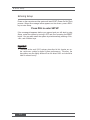
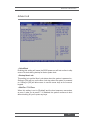
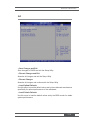
Chapter 3 BIOS Setup ........................................................................... 3-1
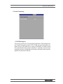
Entering Setup ................................................................................ 3-2
The Menu Bar ................................................................................. 3-4
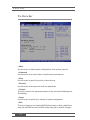
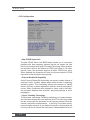
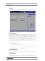
Main ................................................................................................ 3-5
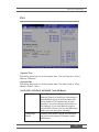
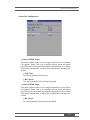
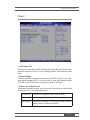
Advanced ........................................................................................ 3-7
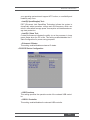
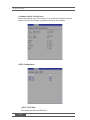
Boot ............................................................................................... 3-13
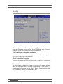
Security ......................................................................................... 3-14
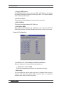
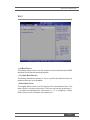
Chipset .......................................................................................... 3-16
Power ............................................................................................ 3-17
Exit ................................................................................................ 3-19
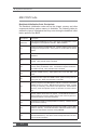
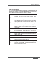
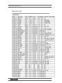
Chapter 4 System Resources ............................................................... 4-1
AMI POST Code ............................................................................. 4-2
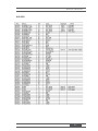
Resource List .................................................................................. 4-6
GPIO Programming ........................................................................ 4-8

Chapter 1
Overview
The MX525D / MX525DC is an Intel® Low-power Mini ITX
Motherboard featuring Intel® Atom™ D525 1.8 GHz Dual Core
processor onboard and supporting DDR3 SODIMM memory
modules. The MX525D is the ATX Power version; the MX525DC
is the DC Power verion.
Based on the innovative Intel
®
ICH8M chipset for optimal
system effi ciency, the IM-PV-C accommodates the Intel
®
Pineview D, Dual core D525, processor and supports 2 DDR3
800MHz SO-DIMM slots to provide the maximum of 4GB
memory capacity.
In the entry-level and mid-range market segment, the MX525D
/ MX525DC provides a high-performance solution for today’s
front-end and general purpose workstation, as well as in the
future.
1

■ Overview
1-2
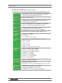
MX525D / MX525DC SPECIFICATIONS
CPU ■ Intel® Atom™ D525 1.8 GHz Dual Core low-power
processor onboard with 533 MHz FSB
Chipset ■ Intel® ICH8M Chipset
Memory ■ Supports two 204-pin SO-DIMM DDR3 800 MHz
memory module up to 4 GB
LAN ■ LAN 1: Intel® 82567V PHY Gigabit LAN Controller
■ LAN 2: Intel® 82574L Gigabit LAN Controller
Audio ■ Realtek® ALC887-VD2-GR HD Audio
■ Line-out, Mic-in, Line-in, 3 Watt x 2 Amplifi er
Graphics ■ Intel® GMA 3150 Graphic Engine, DirectX 9.0C
Expansion
Interface
■ 1 x Mini PCI Express
■ 1 x PCI slot
■ 1 x Compact Flash socket
Back I/O
Panel
■ COM Ports: 1 x RS-232/422/485, 1 x RS-232
■ VGA: 1 x DB-15
■ DVI: 1 x DVI-D
■ LAN: 2 x RJ-45
■ USB: 4 x USB
■ Audio: 1 x 3-jacks Audio connector
Onboard I/O
Headers
■ SATA: 3 x SATA Power Headers
■ USB: 2 x USB Headers (4 Ports)
■ COM Ports: 4 x RS-232 Headers
■ Amplifi er: 1 x Amplifi er
■ LVDS: 1 x LVDS Header
■ Inverter: 1 x Inverter Header
■ Fan: 2 x Fan Headers
Form Factor ■ Mini-ITX: 170mm x 170mm
Power Type ■ MX525D: 20-pin ATX Power
■ MX525DC: 4-pin DC Power ranging from 12V, 14~24V
Mechanical
and
Environment
■ Operating Temperature: -10
o
C to 60
o
C
■ Storage Temperature: -20
o
C to 80
o
C
■ Humidity: 0% ~ 95% RH, Non-Condensing

MX525D / MX525DC
1-3
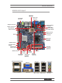
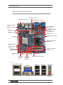
Mainboard Layout
SATA Connector
Chassis
Intrusion
Connector
LVDS Connector
PCI Slot
Clear CMOS Jumper
Serial Port
Connector
Keyboard/Mouse
Connector
Parallel Port
Connector
Amplier Connector
ATX Power
Connector
(Optional)
DIMM Slot
Front Panel
Connector
Front USB
Connector
Fan Power
Connector
LVDS Inverter
Connector
Mini PCIe Slot
GPIO Connector
DC Power
Connector
(Optional)
SATA Power
Connector
(Optional)
CF Mode Jumper
COM Power
Select Jumper
CF Power Select
Jumper
AT/ATX Power
Select Jumper
SPDIF out Connector
Front Audio
Connector
Serial Port RS-232/422/485
DVI-I Port
VGA Port
LAN Jack
USB 2.0 Ports
Line-In Jack
Line-Out Jack
Mic Jack
LAN Jack
USB 2.0 Ports
Serial Port RS-232

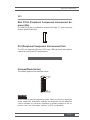
Hardware Setup
This chapter provides you with the information on mainboard
hardware confi gurations. Incorrect setting of jumpers and
connectors may damage your mainboard. Please pay special
attention not to connect these headers in wrong direction. DO NOT
adjust any jumper while the mainboard is powered on.
2
Chapter 2

■ Hardware Setup
2-2
Quick Components Guide
SATA Connector,
p.2-8
Chassis Intrusion Connector,
p.2-8
LVDS Connector, p.2-14
PCI Slot,
p.2-19
Clear CMOS Jumper,
p.2-17
Serial Port Connector, p.2-13
Keyboard/Mouse
Connector, p.2-10
Parallel Port Connector, p.2-12
Amplier Connector,
p.2-9
ATX Power Connector
(Optional), p.2-4
DIMM Slot, p.2-3
Front Panel
Connector,
p.2-10
USB
Connector,
p.2-11
Fan Power
Connector,
p.2-17
LVDS Inverter Connector,
p.2-14
Mini PCIe Slot,
p.2-19
GPIO Connector,
p.2-12
DC Power Connector
(Optional), p.2-4
SATA Power
Connector
(Optional), p.2-4
CF Mode Jumper,
p.2-18
COM Power Select
Jumper, p.2-17
CF Power Select
Jumper, p.2-18
AT/ATX Power
Select Jumper,
p.2-18
SPDIF out Connector,
p.2-15
Front Audio Connector,
p.2-15
Serial Port RS-232/422/485
Back I/O, p.2-5
DVI-I Port
VGA Port
LAN Jack
USB 2.0 Ports
Line-In Jack
Line-Out Jack
Mic Jack
LAN Jack
USB 2.0 Ports
Serial Port RS-232

MX525D / MX525DC
2-3
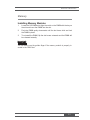
Memory
Installing Memory Modules
1. Locate the SO-DIMM slot. Align the notch on the DIMM with the key on
the slot and insert the DIMM into the slot.
2. Push the DIMM gently downwards until the slot levers click and lock
the DIMM in place.
3. To uninstall the DIMM, fl ip the slot levers outwards and the DIMM will
be released instantly.
Important
Important
You can barely see the golden fi nger if the memory module is properly in-
serted in the DIMM slot.

■ Hardware Setup
2-4
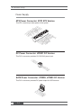
ATX Power Connector: ATX1 ATX Version
This ATX connector provides power to the system.
13.+3.3
V
1.+3.3V
14.-12V
2.+3.3V
15.Ground
3.Ground
16.PS-ON#
4.+5V
17.Ground
5.Ground
18.Ground
6.+5V
19.Ground
7.Ground
22.+5V
10.+12V
20.Res
8.PWR OK
23.+5V
11.+12V
21.+5V
9.5VSB
24.Ground
1
2.+3.3V
DC Power Connector: JPWR1 DC Version
This DC-In connector provides 12V/19V/24V power input.
4.DC
P
owe
r
2.Ground
3.DC
P
owe
r
1
.Ground
SATA Power Connector: JPWR2, JPWR3 DC Version
This DC-In connector provides DC power output for SATA devices.
4+12V
3.GND
2.GND
1.VCC
5
Power Supply

MX525D / MX525DC
2-5
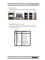
Back Panel I/O
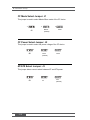
▶ RS-232/422/485 Serial Port Connector
The serial port is a 16550A high speed communications port that sends/
receives 16 bytes FIFOs. You can attach a serial mouse or other serial de-
vices directly to the connector.
PIN SIGNAL DESCRIPTION
1
2
3
4
5
6
7
8
9
DCD
RXD
TXD
DTR
GND
DSR
RTS
CTS
VCC_COM1
or RING
Data Carrier Detect
Receive Data
Transmit Data
Data Terminal Ready
Signal Ground
Data Set Ready
Request To Send
Clear To Send
Voltage output or
RING select setting by
JCOM1_PIN9_SEL1,
Voltage select setting
by JCOMP1
RS-232
Serial Port RS-232/422/485
DVI-I Port
VGA Port
LAN Jack
USB 2.0 Ports
Line-In Jack
Line-Out Jack
Mic Jack
LAN Jack
USB 2.0 Ports
Serial Port RS-232

■ Hardware Setup
2-6
PIN SIGNAL DESCRIPTION
1
2
3
4
5
6
7
8
9
422 TXD-
422 RXD+
422 TXD+
422 RXD-
GND
NC
NC
NC
NC
Transmit Data, Negative
Receive Data, Positive
Transmit Data, Positive
Receive Data, Negative
Signal Ground
No Connection
No Connection
No Connection
No Connection
RS-422
PIN SIGNAL DESCRIPTION
1
2
3
4
5
6
7
8
9
485 TXD-
NC
485 TXD+
NC
GND
NC
NC
NC
NC
Transmit Data, Negative
No Connection
Transmit Data, Positive
No Connection
Signal Ground
No Connection
No Connection
No Connection
No Connection
RS-485
▶ VGA Port
The DB15-pin female connector is provided for monitor.
▶ DVI-I Port
The DVI-I (Digital Visual Interface-Integrated) connector allows you to con-
nect an LCD monitor. It provides a high-speed digital interconnection be-
tween the computer and its display device. To connect an LCD monitor, sim-
ply plug your monitor cable into the DVI connector, and make sure that the
other end of the cable is properly connected to your monitor (refer to your
monitor manual for more information.)

MX525D / MX525DC
2-7
▶ USB 2.0 Port
The USB (Universal Serial Bus) port is for attaching USB devices such as
keyboard, mouse, or other USB-compatible devices.
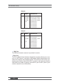
▶ LAN Jack
The standard RJ-45 LAN jack is for connection to the Local Area Network
(LAN). You can connect a network cable to it.
Speed IndicatorActivity Indicator
Left LED Right LED
Active LED 100M/1000M Speed LED
LED Color
Yellow
Yellow
Green
Green/
Orange
Orange
10M Cable
Plug-in
No Transmission
Yellow
Yellow (Lighting) OFF
Transmission
Yellow
Yellow (Blinking) OFF
100M Cable
Plug-in
No Transmission
Yellow
Yellow (Lighting)
Green
Green (Lighting)
Transmission
Yellow
Yellow (Blinking)
Green
Green (Lighting)
1000M Cable
Plug-in
No Transmission
Yellow
Yellow (Lighting)
Orange
Orange (Lighting)
Transmission
Yellow
Yellow (Blinking)
Orange
Orange (Lighting)
In S3/S4/S5 Standby State
Yellow
Yellow (Lighting) OFF
▶ Audio Ports
■ Line-In (Blue) - Line In, is used for external CD player, tapeplayer
or other audio devices.
■ Line-Out (Green) - Line Out, is a connector for speakers or head-
phones.
■ Mic (Pink) - Mic, is a connector for microphones.

■ Hardware Setup
2-8
Connector
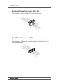
Chassis Intrusion Connector: JCI1
This connector is provided to connect the chassis intrusion switch cable. If
the chassis is opened, the chassis intrusion mechanism will be activated.
The system will record this status and show a warning message on the
screen. To clear the warning, you must enter the BIOS utility and clear the
record.
1
.
C
I
N
T
R
U
2
.
G
r
o
u
n
d
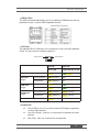
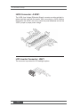
Serial ATA Connector: SATA1 ~ SATA3
This connector is a high-speed Serial ATA interface port. Each connector
can connect one Serial ATA device.
Important
Important
Please do not fold the Serial ATA cable into 90-degree angle. Otherwise,
data loss may occur during transmission.

MX525D / MX525DC
2-9
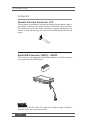
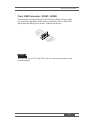
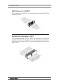
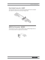
Audio Amplifi er Connector: JAMP1
The JAMP1 is used to connect audio amplifi ers to enhance audio perfor-
mance.
2.AMP_L+
1.AMP_
L
-
4.AMP_R
+
3.AMP_R-
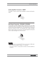
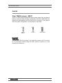
Fan Power Connector: CPUFAN1, SYSFAN1
The fan power connector supports system cooling fan with +12V. When
connecting the wire to the connectors, always note that the red wire is the
positive and should be connected to the +12V; the black wire is Ground and
should be connected to GND. If the mainboard has a System Hardware
Monitor chipset onboard, you must use a specially designed fan with speed
sensor to take advantage of the CPU fan control.
1
.
G
r
o
u
n
d
2
.
+
1
2
V
3
.
S
e
n
s
o
r
4
.
C
o
n
t
r
o
l
Important
Important
• Please refer to the recommended CPU fans at processor’s offi cial web-
site or consult the vendors for proper CPU cooling fan.
• Fan cooler set with 3- or 4-pin power connector are both available for
CPUFAN1.
La pagina si sta caricando...
La pagina si sta caricando...
La pagina si sta caricando...
La pagina si sta caricando...
La pagina si sta caricando...
La pagina si sta caricando...
La pagina si sta caricando...
La pagina si sta caricando...
La pagina si sta caricando...
La pagina si sta caricando...
La pagina si sta caricando...
La pagina si sta caricando...
La pagina si sta caricando...
La pagina si sta caricando...
La pagina si sta caricando...
La pagina si sta caricando...
La pagina si sta caricando...
La pagina si sta caricando...
La pagina si sta caricando...
La pagina si sta caricando...
La pagina si sta caricando...
La pagina si sta caricando...
La pagina si sta caricando...
La pagina si sta caricando...
La pagina si sta caricando...
La pagina si sta caricando...
La pagina si sta caricando...
La pagina si sta caricando...
La pagina si sta caricando...
La pagina si sta caricando...
La pagina si sta caricando...
La pagina si sta caricando...
La pagina si sta caricando...
La pagina si sta caricando...
La pagina si sta caricando...
La pagina si sta caricando...
La pagina si sta caricando...
La pagina si sta caricando...
La pagina si sta caricando...
-
 1
1
-
 2
2
-
 3
3
-
 4
4
-
 5
5
-
 6
6
-
 7
7
-
 8
8
-
 9
9
-
 10
10
-
 11
11
-
 12
12
-
 13
13
-
 14
14
-
 15
15
-
 16
16
-
 17
17
-
 18
18
-
 19
19
-
 20
20
-
 21
21
-
 22
22
-
 23
23
-
 24
24
-
 25
25
-
 26
26
-
 27
27
-
 28
28
-
 29
29
-
 30
30
-
 31
31
-
 32
32
-
 33
33
-
 34
34
-
 35
35
-
 36
36
-
 37
37
-
 38
38
-
 39
39
-
 40
40
-
 41
41
-
 42
42
-
 43
43
-
 44
44
-
 45
45
-
 46
46
-
 47
47
-
 48
48
-
 49
49
-
 50
50
-
 51
51
-
 52
52
-
 53
53
-
 54
54
-
 55
55
-
 56
56
-
 57
57
-
 58
58
-
 59
59


BCM MX525DC Manuale utente
- Categoria
- Schede madri
- Tipo
- Manuale utente
- Questo manuale è adatto anche per
in altre lingue
- English: BCM MX525DC User manual
Documenti correlati
Altri documenti
-
Supermicro SUPER X7SPE-H Manuale utente
-
 Sapphire Audio PI-AM3RS760G2 Quick Installation Manual
-
MSI Cat 5 HDMI Extender System EDP-11 Manuale utente
-
Tyan Thunder h2000M (S3992-E) Manuale utente
-
DeLOCK 65628 Scheda dati
-
-
-
-
MSI MS-7640v2.2 Manuale del proprietario
-
MSI 990FXA-GD65 Manuale del proprietario
