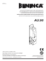
AU.96
MOTORE ELETTROMECCANICO PER PORTE BASCULANTI
ELECTROMECHANICAL MOTOR FOR OVERHEAD DOORS
ELEKTROMECHANISCHER MOTOR FÜR SCHWINGTORE
MOTEUR ÉLECTROMÉCANIQUE POUR PORTES BASCULANTES
MOTOR ELECTROMECÁNICO PARA PUERTAS BASCULANTES
UNIONE NAZIONALE COSTRUTTORI
AUTOMATISMI PER CANCELLI, PORTE,
SERRANDE ED AFFINI
L8542035
Rev. 01/07/01
Libro istruzioni e catalogo ricambi
Operating instructions and spare parts catalogue
Betriebsanleitung und Ersatzteilliste
Livret d’instructions et catalogue des pieces de rechange
Manual de instrucciones y catálogo de recambios

Dichiarazione CE di conformità per macchine
(Direttiva 89/392 CE, Allegato II, parte B)
Divieto di messa in servizio
Fabbricante: Automatismi Benincà SpA
Indirizzo: Via Capitello, 45 - 36066 Sandrigo (VI) - Italia
Dichiara che: l’automazione per porte basculanti modello AU.96.
• è costruito per essere incorporato in una macchina o per essere assemblato con altri macchinari per costituire una macchina con-
siderata dalla Direttiva 89/392 CE, come modicata;
• non è dunque conforme in tutti i punti alle disposizioni di questa Direttiva;
• è conforme alle condizioni delle seguenti altre Direttive CE:
Direttiva bassa tensione 73/23/CEE, 93/68/CEE.
Direttiva compatibilità elettromagnetica 89/336/CEE, 93/68/CEE.
e che:
• sono state applicate le seguenti (parti/clausole di) norme armonizzate:
EN 61000-6-3, EN 61000-6-1, EN 60335-1.
e inoltre dichiara che non è consentito mettere in servizio il macchinario no a che la macchina in cui sarà incorporato o di cui diverrà
componente sia stata identicata e ne sia stata dichiarata la conformità alle condizioni della Direttiva 89/392 CE e alla legislazione
nazionale che la traspone, vale a dire no a che il macchinario di cui alla presente dichiarazione non formi un complesso unico con
la macchina nale.
Benincà Luigi, Responsabile legale.
Sandrigo, 01/07/2006.
Declaration by the manufacturer
(Directive 89/392/EEC, Art. 4.2 and Annex II, sub B)
Divieto di messa in servizio
Manufacturer: Automatismi Benincà SpA
Address: Via Capitello, 45 - 36066 Sandrigo (VI) - Italia
Herewith declares that: the operator for overhead doors model AU.96.
• is intended to be incorpored into machinery or to be assembled with other machinery to constitute machinery covered by Directive
89/392 EEC, as amended;
• does therefore not in every respect comply with the provisions of this Directive;
• does comply with the provisions of the following other EEC Directives:
Direttiva bassa tensione 73/23/CEE, 93/68/CEE.
Direttiva compatibilità elettromagnetica 89/336/CEE, 93/68/CEE.
and that:
• the following (parts/clauses of) harmonized standards have been applied:
EN 61000-6-3, EN 61000-6-1, EN 60335-1.
and furthermore declares that it is not allowed to put the machinery into service until the machinery into which it is to be incorporated
or of which it is to be a component has been found and declared to be in conformity with the provisions of Directive 89/392/EEC and
with national implementing legislation, i.e. as a whole, including the machinery referred to in this declaration.
Benincà Luigi, Responsabile legale.
Sandrigo, 01/07/2006.
La pagina si sta caricando...
La pagina si sta caricando...

5
1. Notizie generali
Per un buon funzionamento dell’automazione in oggetto, la porta basculante deve rispondere alle seguenti
caratteristiche:
- buona robustezza e rigidità
- buona equilibratura
- buona scorrevolezza delle guide.
In ogni caso l’apertura e la chiusura manuali devono potersi eseguire con facilità.
1. General information
For an efcient operation of this automation, the overhead door must have the following features:
- good stoutness and stifness
- good balancing
- good smoothness on its guides
Manual opening and closing must be easy to carry out.
1. Allgemeine Information
Zum guten Betrieb der genannten Automation muß das Kipptor folgende Eigenschaften haben:
- Stärke und Festigkeit
- gute Auswuchtung
- gutes gleiten auf den Führungen.
Öffnung und Schließung von Hand müssen in jedem Fall leicht sein.
1. Notice générales
Pour un bon fonctionnement de l’automatisme en object, la porte basculante doit avoir les suivantes
caractéristiques:
- bonne robustesse et rigidité
- bon équilibrage
- bon déplacement sur les guides
Dans les cas d’ouverture et de fermeture manuelles, les opérations doivent être effectuées avec faci-
lité.
1. Noticias generales
Para un buen funcionamiento de la automatización en objeto, la puerta basculante debe tener las siguientes
características:
- buena solidez y rigidez
- buen equilibrado
- buen deslizamiento de las guías.
De cualquier modo, la apertura y el cierre manuales se deberán poder realizar con facilidad.
Dati tecnici
Technical data
Technische Daten Donnees technique
Datos técnicos
AU.96
Alimentazione
Assorbimento.
Potenza nominale
Coppia nominale
Intermittenza lavoro
Tempo apertura
Grado di protezione
Interv. termoprotez.
Temp. funzionamento
Condensatore
Rumorosità
Lubrificazione
Peso
Power supply
Consumption
Power
Torque
Jogging
Operating time
IP class
Thermal switch trig.
Operat. temperature
Capacitor
Noise level
Lubrication
Weight
Speisung
Stromaufnahme
Leistung
Drehmoment
Betriebsschaltung
Betätigungszeit
IP Grad
Temperaturschutzschalter
Betriebstemperatur
Kondensator
Geräuschentwicklung
Schmierung
Gewicht
Alimentation
Absorption
Puissance
Couple
Intermittence travail
Temps manoeuvre
Degré IP
Interv. protect. therm.
Temp. fonctionnement
Condensateur
Bruit
Lubrification
Poids
Alimentación
Consumo
Potencia
Par
Intermitencia operación
Tiempo maniobra
Índice IP
Interv. termoprotección
Temp. funcionamiento
Condensador
Ruido
Lubrificación
Peso
230Vac (50Hz)
0,85A
170W
480Nm
30%
≈10s
IP40
130°C
-20°C/+70°C
9µF
<70dB
Grasso/Grease
13 kg

6
7
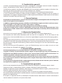
2. Caratteristiche generali
L’ AU.96 è un’automazione per porte basculanti a contrappesi, a montaggio centrale o laterale. Compatto e
lineare, il motoriduttore AU.96 si adatta a qualsiasi tipo di porta basculante.
L’ AU.96 oltre a garantire il massimo dell’afdabilità, offre un movimento continuo, regolare e silenzioso. L’ap-
plicazione è di facile esecuzione e può avvenire mediante viti o saldatura.
L’irreversibilità del motoriduttore assicura la chiusura della porta senza l’impiego di elettroserrature.
In caso di mancanza di corrente lo sblocco avviene mediante la semplice rotazione di una leva situata sul
motoriduttore. Se si applica il dispositivo AU.SE, lo sblocco può essere effettuato sia dall’esterno che dall’interno
mediante la maniglia della porta basculante.
2. General features
Automation for overhead doors, centre or side mounted. Compact and straightforward, the AU.96 geared
motor ts all types of overhead doors.
In addition to guaranteeing maximum reliability, the AU.96 offers regular and silent continuous move-
ment. Installation is easy and can be done with screws or welding.
The irreversible motor ensures door closing without the need of electric locking.
In the event of power failure, release is obtained by turning a lever located on the geared motor. If the
AU.SE device is tted, release can be carried out either externally or internally with the handle of the
overhead door.
2. Allgemeine Eigenshaften
Automationsvorrichtung für kippbare Türen mit zentral oder seitlich montiertem Gegengewicht.
Der kompakte und lineare Motor-Reduzierer paßt sich jeder Art von kippbaren Tür an. Das Modell AU.96
besticht durch höchste Verläßlichkeit und ist durch eine regelmäßige und geräuscharmen Bewegung gekenn-
zeichnet.
Die Anbringung erfolgt problemlos entweder mittels Schrauben oder Schweißung. Die Irreversibilität des Mo-
toreduzierers versichert die perfekte Schließung der Türen ohne Verwendung eines Elektroschlosses.
Bei Stromausfall erfolgt die Endblockierung mittels einfacher Drehung eines auf dem Motoreduzierer ange-
brachten Hebels.
Wird die Vorrichtung AU.SE angebracht, so kann die Entblockierung sowohl von außen als auch von innen
durch Drehen des Handgriffs der kippbaren Tür erfolgen.
2. Caractéristiques générales
AU.96 automatisation pour portes basculantes à contrepoids, montage central ou latéral.
Compact et linéaire, le moto-réducteur AU.96 s’adapte à n’importe quel type de porte basculante. Le
AU.96 assure une abilité maximum et offre en plus un mouvement continu régulier et silencieux. L’in-
stallation est facile à exécuter et peut être faite au moyen de vis ou de soudure.
L’irréversibilité du moto-réducteur assure le fermeture de la porte sans l’emploi de serrure électrique.
En cas de panne de courant le déblocage se fait au moyen d’une simple rotation du levier situé sur le
moto-réducteur.
Si l’on applique le dispositif AU.SE, le déblocage peut être effectué tant de l’intérieur que de l’extérieur
au moyen de la poignée de la porte basculante.
2. Características generales
AU.96 es una automatización para puertas basculantes de contrapesas, de montaje central o lateral.
Compacto y lineal, el motorreductor AU.96 se adapta a todo tipo de puerta basculante.
Además de garantizar máxima abilidad, AU.96 ofrece un movimiento continuo, regular y silencioso. Es fácil
de aplicar, tanto con tornillos como a través de soldadura.
La irreversibilidad del motorreductor asegura el cierre de la puerta sin emplear electrocerraduras.
En caso de fallo de suministro de la corriente eléctrica, la puerta se desbloquea girando simplemente el pomo
puesto en el motorreductor.
Si se aplica el dispositivo AU.SE, el desbloqueo se puede efectuar tando desde el exterior como desde el
interior mediante la manecilla de la puerta basculante.

6
7
3. Accessori indispensabili per il montaggio
- Braccio dritto AU.D oppure braccio curvo AU.C.
- Coppia di tubi L 1500 mm con bussola e staffe AU.45Z (solo per montaggio centrale).
- Bussola calettata AU.45B (solo per montaggio laterale).
3. Necessary assembling equipment
- Straight arm AU.D or curved arm AU.C
- Pair of 1500 mm long tubes with sleeve and asks AU.45Z (only for centre assembling)
- Keyed sleeve AU.45B (only for side assembling).
3. Zur Montage unentbehrliches Zubehör:
- Gerader Arm AU.D oder gebogener Arm AU.C.
- ein Paar Rohre, 1500 mm lang, mit Buchse und Bügeln AU.45Z, nur für Anbringung in der Mitte
- Bügel AU.45B (nur für seitliche Anbringung).
3. Accessoires indispensables pour le montage
- Bras droit AU.D ou bras courbe AU.C.
- Paire de tubes l. 1500 mm avec douille et étrier AU.45Z (seulement pour montage central).
- Douille emboîtée AU.45B (seulement pour montage latéral).
3. Accesorios imprescindibles para el montaje
- Brazo recto AU.D o brazo curvo AU.C.
- Par de tubos L 1500 mm con casquillo y estribos AU.45Z (solo para montaje central).
- Casquillo ensamblado AU.45B (sólo para montaje lateral).
4. Accessori supplementari
- Tubo L 150 mm con bussola e staffa (per montaggio laterale) AU.45T.
- Braccio dritto con bussola saldata AU.D45 (evita la saldatura in opera della bussola AU.45B al braccio
AU.D).
AU.45L bussola di collegamento tra il motoriduttore ed il tubo di torsione senza saldatura (spinata) completo
con tubo di torsione L 2000 mm.
N.B.: Questo accessorio unito al AU.D45 ed al AU.G45 permette l’installazione completa senza effettuare
alcuna saldatura.
- Innesto con staffa AU.G45 (permette il collegamento del braccio AU.D45 al tubo AU.45Z senza saldature).
- Sblocco a maniglia con chiave personalizzata AU.SE.
- Sblocco da esterno con chiave personalizzata AU.E.
- AU.MS96 sblocco a lo.
4. Additional equipment
- 150 mm long tube with sleeve and ask (for side assembling) AU.45T.
- Straight arm with welded sleeve AU.D45 (no need to weld the sleeve AU.45B to arm AU.D).
- AU.45L connection bush between the ratiomotor and the torque tube (pin-locked) complete with 2000
mm long torque tube.
This accessory, together with the AU.D45 and AU.G45, makes possible the complete installation without
any welding.
- Coupling with ask AU.G45 (no need for any welding when connecting arm AU.D45 and tube
AU.45Z).
- Handle release with personalized key AU.SE.
- Outside release with personalized key AU.E.
- AU.MS96 wire release.

8
9
A
R
100
Fig.2 Fig.3
Braccio del basculante
Overhead door arm
Arm der Kipptür
Bras de basculant
Brazo de la puerta basculante
Fig.1
L
L/2
R
100
100
R
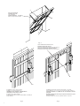
Curare l’allineamento dei due motori.
Carefully align the two motors.
Achten Sie auf die Ausrichtung der beiden Motoren.
Respecter l’alignement des deux moteurs.
Prestar atención a la alineación de los dos motores.
Min 220 mm
Installazione laterale di 2 motori per basculante con portina.
Side installations of 2 motors for an overhead door with small door.
Seitliche Installation von 2 Motoren für ein Schwingtor mit Fuß-
gängertür.
Installation latérale de 2 moteurs pour porte basculante avec porte
piéton incorporée.
Instalación lateral de 2 motores para basculante con puerta.
Installazione motore singolo centrale
Installation of a single central motor
Installation eines einzelnen, zentralen Motors
Installation moteur unique central
Instalación de un motor central
Instalacja jednopunktowa z jednym siłownikiem w centralnym
miejscu bramy

8
9
4. Zusätziches Zubehör:
- Rohr, 150 mm lang, mit Buchse und Bügel AU.45T für seitliche Anbringung.
- Gerader Arm AU.D45 mit geschweißter Buchse (erspart das Schweißen der Buchse AU.45B an den Arm
AU.D bei der Montage).
- AU.45L, Verbindungsbuchse zwischen Getriebemotor und Torsionrohr, ohne Schweißen (verdübelt), komplett
mit Torsionrohr 2000 mm lang.
Dieses Zubehör ermöglicht zusammen mit AU.D45 und AU.G45 vollständige Anbringung ohne irgendeine
Schweißung.
Der Einsatz mit Bügel AU.G45 gestattet die Verbindung des Armes AU.D45 mit dem Rohr AU.45Z ohne
Schweißen.
- Freigabe durch Griff mit individuell gestaltetem Schlüssel AU.SE.
- Freigabe von außen mit individuell gestaltetem Schlüssel AU.E.
- AU.MS96 Freigabe über Draht.
4. Accessoires supplémentaires
- Tube l. 150 mm avec douille et étrier (montage latéral) AU.45T.
- Bras droit avec douille soudée (éviter de souder sur place la douille AU.45B au bras droit AU.D).
- AU.45L douille de liaison entre le moteur-réducteur et le tube de torsion sans soudure (goupillé)
complête de tube de torsion 2000 mm.
N.B. Cet accesoire plus le AU.D45 et le AU.G45, permettent d’effectuer une installation complête sans
devoir souder.
- Enclenchement avec bride AU.G45 (permet la liaison du bras AU.D45 au tube sans soudure).
- Déblocage à manivelle avec clé personalisée AU.SE.
- Déblocage de l’extérieur avec clé personalisée AU.E.
- AU.MS96 déblocage à l.
4. Accesorios suplementarios
- Tubo L 150 mm con casquillo y estribo (para montaje lateral) AU.45T.
- Brazo recto con casquillo soldado AU.D45 (evita soldar el casquillo AU.45B al brazo AU.D durante la colo-
cación).
-AU.45L casquillo de acoplamiento entre el motorreductor y el tubo de torsión sin soldadura (unión por pasa-
dores) provisto de tubo de torsión L 2000 mm.
N.B.: Este accesorio, junto al AU.D45 y al AU.G45 permite la instalación completa sin soldaduras.
- Acoplamiento con estribo AU.G45 (permite el acoplamiento del brazo AU.D45 al tubo AU.45Z sin soldadu-
ras).
- Desbloqueo con manilla con llave personalizada AU.SE.
- Desbloqueo desde el exterior con llave personalizada AU.E
- AU.MS96 desbloqueo con cable.
5. Messa in posa dell’automatismo
5.1 Prefazione
L’automazione con un solo motore a montaggio centrale è consigliabile per porte basculanti di area inferiore
od uguale a 8 m
2
; per dimensioni superiori o per basculanti con portina utilizzare n° 2 motori laterali.
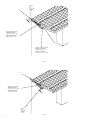
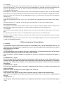
5.2 Operazione n° 1
Individuato l’asse di rotazione della porta basculante A, determinare l’asse R passante inferiormente alla di-
stanza di 100 mm (g. 1); questo è l’asse dell’albero scanalato uscente dal motoriduttore.
Ancorare quindi la piastra del motoriduttore alla porta seguendo le indicazioni delle gg. 2 e 3.
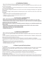
5.3 Operazione n° 2 (g. 4).
Fissare la piastrina P sul montante o sul traverso superiore della basculante oppure a muro a anco del braccio
della porta. (In ogni caso il braccio B deve essere sistemato tra il montante ed il braccio della porta basculan-

10
11
P
Saldare su tutto il contorno
Weld onto all prole
Rundum schweißen
Souder tout autour
Soldar en todo el contorno
B
Fig.4
Fig.6
100
100
Braccio curvo
Bent arm
Gebogener Arm
Bras courve
Brazo curvo
Braccio diritto
Straight arm
Gerader Arm
Bras droit
Brazo recto
Fissare con n° 4 viti autolettanti Ø4.8 o con viti M5 o con rivetti Ø4.8.
Secure with 4 of 4.8 mm Ø self-tapping screws or with M5 screws or with 4.8
mm Ø rivets.
Mit 4 selbstschneidenden Schrauben Ø4.8 oder mit Schrauben M5 oder mit Nieten
Ø4.8 befestigen.
Fixer avec 4 vis taraud Ø4.8 ou vis M5 ou rivets Ø4.8.
Fijar con 4 tornillos de autorrosca Ø4.8 o con tornillos M5 o con remaches Ø4.8.
Regolare per ottenere il parallelismo del tubo con la porta basculante
Adjust until the tube is parallel to the overhead door
Regulieren, bis Rohr und Kipptor parallel sind.
Régler pour obtenir le parallélisme du tube avec la porte basculante
Regular para que el tubo esté paralelo a la puerta basculante
Fig.5
T
S
R
Mettere a livello
Set level
Gerade ausrichten
Mettre de niveau
Nivelar

10
11
te; se questo spazio è insufciente utilizzare il braccio curvo art. AU.C che permette di lavorare in asse con il
braccio della porta basculante).
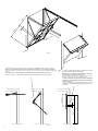
5.4 Operazione n° 3 (g. 6).
Fissare provvisoriamente la staffa S con il tubo T inlato sia in quest’ultima che nell’albero scanalato del
motoriduttore.
Rilevare la misura del tubo T in modo che sia allineato al braccio B.
Tagliare quindi il tubo a misura.
Fissare ora la staffa S mediante viti o rivetti avendo cura di mettere in bolla il tubo T.
Quest’ultimo deve anche essere parallelo al telo della basculante; a tal proposito usufruire della regolazione
di cui g. 5.
5.5 Operazione n° 4
Portare la porta basculante in apertura e tagliare i due componenti del braccio dritto secondo le indicazioni
delle gg. 7 e 8.
Saldare poi il piatto del braccio al tubo T (g. 7) oppure utilizzare il braccio AU.D45.
Inlare il piatto nel tubo e quindi ssare quest’ultimo al piatto P mediante vite M10 e dado autobloccante (in
dotazione).
5.6 Operazione n° 5
Se necessario riequilibrare la porta aumentando i contrappesi o il tiro delle molle in modo che le manovre
manuali risultino facili da compiere.
5. Installation
5.1 Foreword
The automation with one only centre mounted motor is recommended for 8 sqm or smaller overhead
doors; overhead doors larger in size or with single-swing door should be equipped with 2 side mounted
motors.
5.2 Once found the overhead door rotation axis A, determine axis R, 100 mm underneath (g. 1); this
is the splined shaft axis coming from the ratiomotor. Now, secure the ratiomotor base to the door as
per g. 2 and 3.
5.3 Operation no. 2 (g. 4)
Secure plate P to the top jamb of the door or to the wall on the door arm side. (The arm B must be
located between the jamb and the arm of the overhead door. If there is no sufcient space, use the
curved arm AU.C which permits to work axially to the overhead door arm).
5.4 Operation no. 3 (g. 6)
Temporarily fasten the ask S with the tube T which is partially inserted both in the ask and in the
ratiomotor splined shaft. Determine the tube T measure so that it is aligned to arm B. Now cut the tube
to size. Secure the ask S through screws or rivets after making sure the tube T is livelled and parallel
to the overhead sheet (for its adjustment see g. 5)
5.5 Operation no. 4
Open the overhead door and cut the 2 straight arm components as per indications given on g. 7 and
8. Now weld the arm plate to the tube T (g. 7) or use the arm AU.D45.
Insert the plate into the tube and secure them to each other through an M10 screw and a self blocking
nut (supplied as part of the equipment).
5.6 If necessary, balance the door by increasing the balance weights or the spring compression so that
all manual operations are easier.
5. Montage der Automation
5.1 Vorwort
Die Automation mit nur einem Motor zur Anbringung in der Mitte empfiehlt sich für Kipptüren, deren Fläche
8 m
2
oder weniger mißt; bei größeren Maßen oder bei Kipptoren mit Personentür setze man zwei seitliche
Motoren ein.

12
13
Fig.8
Fig.7
P
10
Tagliare
Cut
Schneiden
Couper
Cortar
Piatto del braccio diritto
Straight arm plate
Platte des geraden Armes
Méplat du bras droit
Plato del brazo recto
T
Saldare su tutto il contorno
Weld onto all prole
Rundum schweißen
Souder tout autour
Soldar en todo el contorno
P
10
Tagliare
Cut
Schneiden
Couper
Cortar
Tubo del braccio diritto
Straight arm tube
Rohr des geraden Armes
Tube de bras droit
Tubo del brazo recto
La pagina si sta caricando...
La pagina si sta caricando...
La pagina si sta caricando...
La pagina si sta caricando...

16
17
6.3 Spring overhead doors (follow instructions given in point 5 for assembly).
N.B. In order to be automated through the AU.96, the doors have to be vertical guided.
6. Besondere Anwendungen
Außer den normalen Kipptoren mit Gegengewicht und sekrechten Führungen kann man mit AU.96 automa-
tisieren:
6.1 Türen mit waagerechten und senkrechten Führungen (Zeichnung 9); die Anbringung gleicht der in Punkt
5 beschriebenen.
6.2 Gelenkkipptüren (Zeichnung 10).
Zur Anbringung lese man Punkt 5 mit den Anweisungen auf Zeichnung 10.
6.3 Federkipptore - bei der Anbringung befolge man die Anweisungen in Punkt 5.
Um mit AU.96 automatisiert zu werden, müssen diese Tore jedoch eine senkrechte Führung haben.
6. Applications particuliaires
Outres les normales portes basculantes (à contre-poids et guides verticales) le permet d’automati-
ser:
6.1 Les portes à guides horizontales et verticales g. 9 (c’est la même installation que celle décrite au
paragraphe 5)
6.2 Portes basculantes articulées (g. 10)
Pour l’installation, suivre la description du paragraphe 5 en y ajoutant les indications de la gure 10.
6.3 Portes basculantes à ressorts (pour le montage suivre la description du paragraphe 5)
N.B. Pour être parfaitement automatisées avec le AU.96, elles doivent être à guidage vertical.
6. Aplicaciones particulares
Además de las normales puertas basculantes (de contrapeso y guías verticales), con AU.96 se automati-
zan:
6.1 Puertas de guías horizontales y verticales g. 9 (se instalan de forma análoga a la descrita en el punto 5).
6.2 Puertas basculantes articuladas (g. 10). Para la instalación seguir el punto 5 integrado con las indicacio-
nes de la g.10.
6.3 Puertas basculantes de muelle (para el montaje seguir las indicaciones del punto 5).
N.B.: Se podrán automatizar estas puertas a condición de que sean de guía vertical.
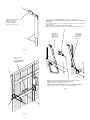
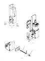
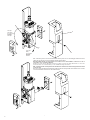
7. Manovra manuale
La manovra manuale della porta basculante è realizzabile nell’ AU.96 in diversi modi:
7.1 Sblocco interno a maniglia (g. 11).
7.2 Sblocco interno - esterno a maniglia con chiave personalizzata (g. 12).
7.3 Sblocco esterno con chiave personalizzata (g. 13).
• Levare il blocchetto con la chiave personalizzata 1.
• Sbloccare tramite la chiave a brugola 2.
7.4 Sblocco a lo art. AU.MS96 (gg. 14-15-16).
• Togliere il supporto S svitando le 4 viti V (g. 14).
• Premontare il supporto S1 (g. 15).
• Fissare il supporto S1 mediante le due viti V1.
• Inlare il cavo di acciaio C sulla leva L.
• Passare la guaina G con il capocorda K no a mandarla in battuta sul foro F.
• Fissare il cavo di acciaio C nella maniglia secondo g. 16.
• Ruotare la maniglia per sbloccare.
• Ruotando nuovamente la maniglia, la prima manovra ripristinerà il normale funzionamento.
7. Manual operation
The overhead door manual operation can be carried out as follows:
7.1 Handle internal release (g. 11)
La pagina si sta caricando...
La pagina si sta caricando...

20
21
Fig.17
A
V
C
G
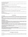
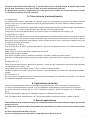
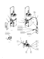
N.B.: I necorsa possono essere montati entrambi da una parte, nel caso di montaggio laterale del motore,
oppure uno su ogni lato in caso di montaggio centrale di quest’ultimo.
Note: Both limit switches can be mounted on one side in case of side installation of the motor or one on
each side in case of central installation.
Notabene: Im Falle daß, die Montage des Motores seitlich ist, können die beide Entschalter von einer Seite
montiert werden, oder ein Entschalter pro Seite im Mittelmontage des Motores.
N.B.: Les deux ns de course peuvent être montées d’un côté dans le cas de montage latéral du moteur
ou un par côté.
Nota : En caso de instalacion lateral del motor ambos nales de carrera pueden ser instalados de un solo lado,
en caso de instalacion central uno a cada lado del motor.
Anticipa.
Anticipate.
Beschleunigt.
Anticipe.
Anticipa.
Posticipa.
Delay.
Verlangsamt.
Retarde.
Retrasa.

20
21
7. Maniobra manual
La maniobra manual de la puerta basculante se ejecuta de varias maneras:
7.1 Desbloqueo interno de manilla (fig. 11).
7.2 Desbloqueo interior/exterior de manilla con llave personalizada (Fig.12)
7.3 Desbloqueo exterior con llave personalizada (fig. 13).
• Quitar el bloque con la llave personalizada 1.
• Desbloquear con la llave 2.
7.4 Desbloqueo con cable art. AU.MS96 (fig. 14-15-16).
• Quitar el soporte S destornillando los 4 tornillos V (g. 14)
• Preasemblar el soporte S1 (g. 15)
• Fijar el soporte S1 mediante los dos tornillos V1
• Introducir el cable de acero C en la palanca L
• Pasar la funda G con el con el cable K hasta llegar a su tope en el agujero F
• Fijar el cable de acero C en la manecilla como en g. 16
• Girar la manilla para el desbloqueo.
• Girar la manilla otra vez, la primera maniobra restablecerá el funcionamiento normal.
8. Regolazione dei necorsa (g. 17)
L’ AU.96 dispone di necorsa incorporati sia per l’apertura che per la chiusura; è comunque consigliabile, usare
il necorsa solo in apertura.
Per la regolazione agire come segue:
• Svitare la vite V e togliere il carter C.
• Allentare il grano G.
• Ritardare o anticipare l’intervento del necorsa ruotando la camma A e serrare moderatamente il grano G.
8. Limit stops adjustment (g. 17)
The AU.96 is equipped with limit stops both for the opening and the closing; it is anyway advisable to
use the limit stops only when opening.
For the adjustment proceed as follows:
• Unscrew the screws V and the case C.
• Loosen the grain G.
• Delay or anticipate the limit stop intervention by rotating the cam A and tighten the grain G.
8. Einstellung der Endschalter (Bild 17)
In das AU.96 sind Endschalter zum Öffnen und Schließen eingebaut; ist es jedoch ratsam, den Endschalter
nur beim Öffnen zu gebrauchen.
Man stellt ihn wie folgt ein:
• Schraube V heraus- und Haube C abnehmen.
• Stift G lockern.
• Tätigkeit des Endschalters verlangsamen oder beschleunigen, indem Sie Nocke A drehen und Stift G mäßig
anziehen.
8. Réglage des ns de course (g. 17)
Le AU.96 dispose de ns de course incorporés aussi bien pour l’ouverture que pour la fermeture. Il est
néanmoins conseillé, d’utiliser le n de course uniquemente en ouverture.
Pour le réglage, veuillez agir de la façon suivante:
• Dévisser le vis V et enlever le carter C.
• Desserrer l’ergot G.
• Retarder ou anticiper l’intervention du n de course en tournant la came A et en serrant modérément
l’ergot G.

22
23
8. Regulación de los nes de carrera (g. 17)
El AU.96 dispone de finales de carrera incorporados tanto en apertura como en cierre ; de todas formas se aconseja
usar el final de carrera solo en apertura.
Para su ajuste proceder como sigue :
• Extraer el tornillo V y quitar el cárter C.
• Aojar el tornillo sin cabeza G.
• Retardar o anticipar la intervención de los nes de carrera girando el álabe A y apretar con moderación el
tornillo sin cabeza G.
ATTENZIONE
Tutti i prodotti Benincà sono coperti da polizza assicurativa che risponde di eventuali danni a cose o persone causati da
difetti di fabbricazione, richiede però la marcatura CE della ”macchina” e l’utilizzo di componenti originali Benincà.
WARNING
All Benincá products are covered by insurance policy for any possible damages to objects and persons caused by
construction faults under condition that the entire system be marked CE and only Benincá parts be used.
ACHTUNG
Alle Produkte BENINCA’ wurden mit einem Versicherungsschein versehen, der alle eventuellen Schäden an Dingen oder
Personen abdeckt, die durch Herstellungsdefekte hervorgerufen wurden, vorausgesetzt, das Gerät besitzt die Kenn-
zeichnung EU und es wurden original BENINCA’ Einzelkomponenten verwendet.
ATTENTION
Tous les produits Benincà sont couverts par une police d’assurance qui répond d’éventuels préjudices corporels ou matériels
provoqués à cause de défauts de fabrication, mais qui requiert toutefois le marquage CE de la “machine” et l’utilisation de
pièces de rechange d’origine Benincà.
ATENCIÓN
Todos los productos Benincà están cubiertos por una póliza de seguros que responde de eventuales daños a personas
o cosas, causados por defectos de fabricación, requiere sin embargo la marca CE de la ”máquina” y la utilización de
componentes originales Benincà.

22
23
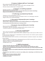
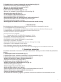
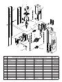
Pos. Denominazione - Description - Bezeichnung - Dénomination - Denominación Cod.
1
Carter
Cover
Deckel
Couvercle
Tapa
9686105
2
Lampadina
Lamp
Lampe
Lampe
Lampára
9686106
3
Supporto
Support
Stütze
Support
Soporte
9686175
4
Calotta motore
Motor cup
Motordeckel
Calotte moteur
Estator
9686166
5
Albero motore
Shaft
Welle mit Rotor
Arbre moteur
Eje motor
9686168
6
Piastra 530mm
Plate
Platte
Plaque
Base de fijación
9686206
7
Piastra 1250mm
Plate
Platte
Plaque
Base de fijación
9686165
8
Guarnizione
Gasket
Dichtung
Guarniture
Junta
9686169
9
Pignone
Gear
Zahnrad
Engrenage
Piñon
9686170
10
Albero uscita
Output shaft
Welle
Arbre
Eje de salida
9686009
11
Finecorsa
Limit stop
Endschalter
Fin de course
Final de carrera
9686172
12
Maniglia sblocco
Release lever
Handgriff
Manette
Pal. de desbloq.
9686178
13
Pignone
Gear
Zahnrad
Engrenage
Piñon
9686011
1
2
3
4
5
6
7
8
9
10
13
11
12

AUTOMATISMI BENINCÀ SpA - Via Capitello, 45 - 36066 Sandrigo (VI) - Tel. 0444 751030 r.a. - Fax 0444 759728
-
 1
1
-
 2
2
-
 3
3
-
 4
4
-
 5
5
-
 6
6
-
 7
7
-
 8
8
-
 9
9
-
 10
10
-
 11
11
-
 12
12
-
 13
13
-
 14
14
-
 15
15
-
 16
16
-
 17
17
-
 18
18
-
 19
19
-
 20
20
-
 21
21
-
 22
22
-
 23
23
-
 24
24


Beninca SPAZIO AU.96 Guida utente
- Tipo
- Guida utente
- Questo manuale è adatto anche per
in altre lingue
- English: Beninca SPAZIO AU.96 User guide
- français: Beninca SPAZIO AU.96 Mode d'emploi
- español: Beninca SPAZIO AU.96 Guía del usuario
- Deutsch: Beninca SPAZIO AU.96 Benutzerhandbuch