Rockford Fosgate T1 T-S Installation & Operation Manual
- Categoria
- Altoparlanti
- Tipo
- Installation & Operation Manual

I
l
WE
A
COMPONENT
SPEAKERS
T152-S
•
T16-S
T1650-S
•
T1675-S
•
T1
T-S
Serial
Number:
_____
_
Date
of
Purchase:
____
_
Installation
&
Operation

2
Introduction
Dear
Customer,
Congratulations
on
your
purchase
of
the
world's
finest
brand
of
audio
products.
At
Rockford
Fosgate
we
are
fanatics
about
musical
reproduc-
tion
at
its
best,
and
we
are
pleased
you
chose
our
product.
Through
years
of
engineering
expertise,
hand
craftsmanship
and
critical
testing
procedures,
we
have
created
a
wide
range
of
products
that
reproduce
music
with
all
the
clarity
and
richness
you
deserve.
For
maximum
performance
we
recommend
you
have
your
new
Rockford
Fosgate
product
installed
by
an
Authorized
Rockford
Fosgate
Dealer,
as
we
provide
specialized
training
through
Rockford
Technical
Training
Institute
(RTTI).
Please
read
your
warranty
and
retain
your
receipt
and
original
carton
for
possible
future
use.
Great
product
and
competent
installations
are
only
a
piece
of
the
puzzle
when
it
comes
to
your
system.
Make
sure
that
your
installer
is
using
100%
authentic
installation
accessories
from
Rockford
Fosgate
in
your
installation.
Rockford
Fosgate
has
everything
from
RCA
cables
and
speaker
wire
to
power
wire
and
battery
connectors.
Insist
on
it!
After
all,
your
new
system
deserves
nothing
but
the
best.
To
add
the
finishing
touch
to
your
new
Rockford
Fosgate
image,
order
your
Rockford
accessories,
which
include
everything
from
T-shirts
to
hats.
Visit
our
web
site
for
the
latest
information
on
all
Rockford
products;
www.
rockfordfosgate.
com
or,
in
the
U.S.
call1-800-669-9899
or
FAX
1-800-398-3985.
For
all
other
countries,
call
+001-480-967-3565
or
FAX
+001-480-966-3983.
Table
of
Content
2
Introduction
3-5
Specifications
6-11
Installation
Installation
Considerations
Mounting
Wiring
Tweeter
Axis/Attenuation
Switch
10-11
Additional
Languages
French
Spanish
German
Italian
12
Limited
Warranty
Information
If,
after
reading
your
manual,
you
still
have
questions
regarding
this
prod-
uct,
we
recommend
that
you
see
your
Rockford
Fosgate
dealer.
If
you
need
further
assistance,
you
can
call
us
direct
at
1-800-669-9899.
Be
sure
to
have
your
serial
number,
model
number
and
date
of
purchase
available
when
you
call.
Safety
This
symbol
with
"WARNING"
is
intended
to
alert
the
user
to
the
presence
of
important
1f'.
WARNING
instructions.
Failure
to
heed
the
instructions
~
will
result
in
severe
injury
or
death.
This
symbol
with
"CAUTION"
is
intended
to
alert
the
user
to
the
presence
of
important
n.._
instructions.
Failure
to
heed
the
instructions
~
CAUTION
can
result
in
injury
or
unit
damage.
•
To
prevent
injury
and
damage
to
the
unit,
please
read
and
follow
the
instructions
in
this
manual.
We
want
you
to
enjoy
this
system,
not
get
a
headache.
•
If
you
feel
unsure
about
installing
this
system
yourself,
have
it
installed
by
a
qualified
Rockford
Fosgate
technician.
•
Before
installation,
disconnect
the
battery
negative
(-)
terminal
to
prevent
damage
to
the
unit,
fire
and/or
possible
injury.
©2014
Rockford
Corporation.
All
Rights
Reserved.
ROCKFORD
FOSGATE
and
associated
ogos
w'lere
applicable
are
registered
tradenarks
of
Rockford
Cor-
poration
in
the
United
States
and/or
other
countries.
All
other
trademarks
are
the
property
of
the
r
respt~:
ve
owners.
Specifications
Sl,bJect
to
cnange
without
notice

'-'t
Uti't
...
Mod
el
.
l'
,/1
?:
C
a~
J
~
4
}~1\
f.
'>
.~
r'l
omi
na
l
Di
am
e
ter
D
escriptio
n
Nom
inal
Im
p
edanc
e
F
req
ue
n
cy
Respo
nse
Voice
C
oil
Di
ame
ter
P
ower
Ra
tin
g
(R
MS/Pca
k)
Fs
-
Free
A
ir
Resonance
Ots
Va
s
Sens
it
ivity
(1
W/
1M
)
Sensitivi
ty
(2
83V/1Ml
X
max
Mounting
Diame
t
er
Mounting
Depth
Grille/Tr11n
R1ng
Adaptor
Pl
ate
Specifications
1152-S
116-S
11650-S
11675-S
11T-S
5.25"
6"
6.5"
6.75"
1.0"
(133mm)
(153mm)
(165mm)
(171
.
5mm)
(25mm)
2-Way
2-Way
2-Way
2-Way
Tweeter
40 40
40
40 40
65-22kHz
60-22kHz
47-20kHz
55-22kHz
3kHz-22kHz
1.1"
1.
1"
1.2"
1.2"
1.0"
(27.9mm)
(27.9mm)
(30
.
5mm)
(30.5mm)
(25.4mm)
75W
I
150W
BOW
I
160W
BOW
1160W
100W
1
200W
75W
I150W
65Hz 67Hz
62Hz
56
Hz
1.B
kHz
0.60
O.B
0.74
0.
59
NIA
0.34
ft3
0.35
ft
3
0.43
ft
3
0.56ft
3
NIA
(9.6L)
(9
.
BL)
(12.2L)
(15
.
9L)
B?dB
B6dB
BBdB
89dB
90dB
90dB
B9dB
91dB
92dB
93dB
0.
16
"
0.
16
"
0.2"
0.
15"
NIA
(4.0mm)
(4
.2mm)
(5mm)
(3.7mm
)
4.
B1
"
5.05"
5.
51"
5.6B"
1.75"
(1
22.
2mm)
(128.2mm)
(140mm)
(144
.2
mm
)
(45mm)
1.99
"
1.93
" 2.
52
" 2.52"
0.91
"
(50
.
5mm)
(49.0mm)
(64
.
0mm)
(64
.
0m
m) (2
3mm)
YES
YES
YES
YES
YES
YE
S
YES
NO
YES
NO
See
pages
4-5
for
add
i
tional
dimen
s
ion
s
CE
A
2031
Powe
r
handling
on
Roc
kf
ord
Fosga
te
speakers
co
nf
or
m to
CEA
-2031
indu
stry
sta
nd
ar
ds
. T
hi
s
mea
ns
yo
ur spea
ke
r h
as
th
e
capacity
to
handle
po
wer
under
cont
i
nuo
us d
ema
nd,
not
ins
t
anta
n
eo
us
po
wer
h
an
d
ling
th
at ov
er
ti
me c
an
dam
age
vo
ice
coils.
3

Specifications
T152-5
T1S-5
6.
69
'
(170.0mm)
Diameter
T1650-5
T1675-5
il
lu
s.
-1.1
4
5.43"
(138.0mm)
Diameter
\\1
~
~
:]1_1
6.22"
(158.0mm)
ldfo
•11:11
........._
rll
:=:11
J
4.81 '
!---
,
122.2mm)
~
1.06"
(27.0mm)
I
1
1
2.45
(62.2
mm
)
1.99"
.1
(50.
rm)
6.89"
?
~:
6.10'
1=
4
(1
75.0mm)
(155
.0mm)
Diameter
5.59"
(142.0mm)
6.18'
(157.
0mm
)
Diameter
Diameter
6.1
2'
(155.5mm)
Diameter
6.97"
(1
77.0
mm)
¢
6.77"
(172mm)
5.51'
(140
mm
)
1.18"
(29.
9m
m)
1.
18
"
(29.9mm)
l
1.
24
"
(31.6mm)
3.03"
(76.9mm)

T1T-S
Surface Mount
Flush
Mount
Tweeter
Crossover
Component Crossover
0.30"
(Bmm)
4.
57
"
(116mm)
- - - - 1
4.57"
(
11
6
mm)
~
-
Specifications
(23mm)
r
0.91"
r
(is~~
)
---j
·u
u
LTLrLJ
-u
-
----,--
1.18"
__:;:_
m)
I
-
3.16
"
(BOmm)
--
~
]
0
.
97
"
~
(25mm)
I
1.
26
"
I
1--
(32mm)
--J
i
liu
s.-1
.2
5

6
Installation
Contents
•
(1)
Pair
Power
Series
Full
Range
Component
Speakers
•
(1)
Pair
of
grilles/trim
rings
•
Mounting
Hardware
•
(1)
Set
adapter
plates
(5"x7"/6"x9")
Installation
Considerations
Before
beginning
any
installation,
follow
these
simple
rules:
1.
Be
sure
to
carefully
read
and
understand
the
instructions
before
attempting
to
install
these
speakers.
2.
For
safety,
disconnect
the
negative
lead
from
the
battery
prior
to
beginning
the
installation.
3.
For
easier
assembly,
we
suggest
you
run
all
wires
prior
to
mounting
your
speakers
in
place.
4.
Use
high
quality
connectors
for
a
reliable
installation
and
to
minimize
signal
or
power
loss.
5.
Think
before
you
drill!
Be
careful
not
to
cut
or
drill
into
gas
tanks,
fuel
lines,
brake
or
hydraulic
lines,
vacuum
lines
or
electrical
wiring
when
working
on
any
vehicle.
If
installation
in
a
boat,
take
care
not
to
cut
or
drill
through
the
main
hull.
6.
Never
run
wires
underneath
the
vehicle
.
Running
the
wires
inside
the
vehicle
or
hull
area
provides
the
best
protection.
7.
Avoid
running
wires
over
or
through
sharp
edges.
Use
rubber
or
plastic
grommets
to
protect
any
wires
routed
through
metal,
especially
the
firewall.
Mounting
Mid-Bass
1.
Determine
where
the
speakers
will
be
mounted.
Ensure
an
area
large
enough
for
the
speaker
to
mount
evenly
.
Be
sure
that
the
mounting
location
is
deep
enough
for
the
speaker
to
fit;
if
mounting
in
a
door,
operate
all
functions
(windows,
locks,
etc
.)
through
their
entire
operating
range
to
ensure
there
is
no
obstruction.
2.
Refer
to
the
specification
chart
to
determine
the
proper
diameter
hole
to
cut
for
your
speaker
model.
Cutting
and
mounting
templates
can
be
found
at
www.rockfordfosgate.com.
3.
Mark
the
locations
for
the
mounting
screws.
Drill
the
holes
with
a
1/8"
bit.
-
4.
Feed
the
speaker
wires
through
the
cutout
and
connect
to
the
speaker
terminals
.
Be
sure
to
observe
proper
polarity
when
connecting
the
wires
.
The
speaker's
positive
terminal
is
indicated
with
a
"+".
5.
Fit
the
trim
ring
over
the
speaker
and
mount
into
place
using
four
(4)
screws.
6.
Tighten
the
screws
until
the
speaker
is
s
nug
in
place
to
prevent
rattling
.
Do
not
over
tighten
the
screws.
Mounting
tab
removal
for
some
installations
0
Use
pliers
to
break
off
plastic
tab
.
i!lus.-2.1
Example
of
standard
door
installation
...
·~·
..
:)·~
:~
~-
}?~
i,t
!?~
-"'~:
··0o
Align
Ho
les
.
...-
·
.·····
. ....
Tweeter-
Discreet
Dual
Clamp
(DOC™)
1.
Determine
where
the
speakers
will
be
mounted.
Ens
ur
e
an
area
large
enough
for
the
speaker
to
mount
evenly.
Be
sure
that
the
mounting
location
is
deep
enough
fo
r
the
speaker
to
fit
;
if
mounting
in
a
door
,
operate
all
functions
(windows,
locks,
etc
.)
th
r
ough
their
entire
operating
range
to
ensure
there
is
no
obstructio
n.
2.
Mark
the
location
for
the
mounting
hole.
Drill
the
hole
with
a
standard
1.75
inch
(45mm)
hole
saw.
3.
With
a
single
center
screw
secure
the
inner
cup
fr
om
the
front
of
the
door
panel
to
the
outer
cup
from
back
of
the
door
panel.
Tighten
the
screw
until
balanced
pressure
is
applied
to
both
f
aces
of
the
mounting
surface.
4.
Feed
the
speaker
wires
through
the
cutout
and
connect
to
the
speaker
terminals
.
Be
sure
to
obse
r
ve
proper
polarity
when
connecting
the
wires.
The
speaker's
lead
wires
are
indicated
with
a
RED
wire
"
+"
and
a
BLACK
wire"-".
5.
Simply
snap
the
tweeter
into
place
and
secure
wi
th
a
snap-on
trim
ring.
Re
moval
is
easy
if
needed.
The
protective
g
rille
on
the
twe
e
ter
is
non-removable
and
an
i
ntegra
l
part
of
the
design
.
Use
tip
of a
small
flat
sc
rewdri
ve
r
to
remove
tw
eete
r
Example
of
tweeter
mounting
ll!:inn
nimP.P.t
nn:~l
r.lllmn
mnr.™l

Wiring
Standard
1.
Use
illustration
for
proper
connection
and
be
sure
to
maintain
speaker
In
stallation/System Setup
·
!I
us
-:
u
polarity.
2.
Use
only
"TWEETER"
input(s).
Example
of
T1
Component
Standard/Bi·Amp
Wiring
Default
Setting
,
...........
..
, '
I
81-AMP
"
Bi-amp
1.
Use
illustration
for
proper
connection
and
be
sure
to
maintain
speaker
polarity.
1
t0FF,
r-ON',
...........................
\~
..
EJ,f
Standard
Mode
-
..
,
..
-
.
.
2.
Remove
4
screws
from
crossover
bottom
to
detatch
cover.
3.
When
BI-AMP
switched
OFF
for
one
amplifier,
use
only
"TWT"
input.
4.
When
BI-AMP
switched
ON
for
two
ded
i
cated
amplifier,
use
both
"TWT"
and
"WFR"
inputs
Remove
4
screws
from
~
bottom
to
detatch
cover
#
T1T-S
Crossover
1.
Use
illu
s
tration
for
proper
connection.
2.
Be
sure
to
maintain
speaker
polarity.
..........
3.
Connecting
the
positive
wire
to
OdB
matches
the
amplitude
of
the
tweeter
to
the
mid-range
(woofer).
4.
Connecting
positive
wire
to
-2dB
or
-
4dB
to
reduce
the
amplitu
de
of
the
tw
ee
ter
-2dB
or
-4dB
lower
than
the
mid-range,
(ideal
for
tweeters
lo
c
ated
high
in
door
panels
and
mid-range
low
in
the
kick
panel)
.
Tweeter
On-Axis
Tweeter
Off-Axis
f
-
i!
i
US
.
AA
3,2
Example
of
TH·S
wiring
........
. ...................................
.
.
.
(TWT)
Tweeter
ON/OFF
Axis
Switch
Tweeter
(TWT)
Tweeter
(TWT)
1.
Set
to
ON
or
OFF
to
matc
h
position
of
tweeter
relative
to
listener.
Default
OFF
position
satisfies
most
installations.
Tweeter
Attenuation
Switch
1.
OdB
ma
t
ches
the
amplitude
(no
increase/no
attenuatio
n)
of
the
tweeter
to
the
same
level
as
the
mid-range
(woofer).
2.
+2dB
in
c
reases
and
-2dB
reduces
the
amplitude
of
tw
ee
ter
in
relation
to
the
mid-range,
(ideal
when
matching
offset
installa
t
ion
like
tw
e
eters
located
h
igh
in
door
pa
nels
and
mid
ranges
low
in
kick
panels).
Tweete
r
On
-A
x
is
Twe
eter
Off
-Axis
i!i
us
.-
41
Example
of
T1
component
tweeter
setup
'
..............................................
..
(J.L
.
.,
Ax
iss•tJI;
....
,.
..
..
-~
..
..............................
,
...
..
.......
.
.
.
.
.
.
.
.
.
.
.
.
7

Installation
il
lu
s.
-
5.
1
8
Adapter
Plate
Template·
6.75"
Hole
Mounting
Remove
Shaded
Areas
to
M
oun
t
5
.25
"
(
T15
2-S)
Remove
Shaded
Areas
to
Moun
t
6"
(T16-S)

Adapter
Plate
Template-
6"x9"
Hole
Mounting
Mounting
for
5.25
"
(T152-S)
Installation
illus.
-
5.2
9

10
Fran(_(ais
Considerations
Concernant
L'installation
Avant
de
commencer
l'installatio
n,
suivez
les
regles
ci-dessous:
1.
Veillez
il
bien
lire
et
comprendre
les
instructions
avant
d'
essayer
d'installer
les
haut-parl
eurs.
2.
Par
mesure
de
securite,
debranchez
le
fil
negatif
de
Ia
b
atte
r
ie
avant
de
commencer
!'
i
nstallat
i
on.
3.
Pour
faciliter
le
montage
des
haut-parleurs
,
il
est
conseille
d'installer
taus
les
cables
au
pn\alable.
4.
Utilisez
des
connec
teurs
de
haute
qualite
pour
assurer
une
i
nstallation
liable
et
reduire
au
minimum
Ia
perte
de
signal
au
de
puissance.
5.
Reflechissez
bien
avant
de
percer.Veillez
il
ne
pas
couper
au
percer
le
reservoir
d'essence,
le
ca
blage
electrique
au
les
condu
i
tes
de
carburant,
de
f
re
inage
h
yd
raulique
au
de
depres
sion
en
tra
vail
lant
sur
un
vehicule
.
En
cas
d'installation
sur
un
bateau
,
veillez
a
ne
pas
couper
au
per
ce
r
Ia
c
oque
principale.
6.
Ne
jamais
faire
passer
de
fils
sous
le
vehicule.
Leur
in
stall
ation
ill'interieur
du
vehicule
au
de
Ia
coque
assure
Ia
meilleure
protection
.
7.
tvitez
de
faire
passer
des
fils
sur
des
bards
tranchants
au
dans
des
orifices
il
aretes
vives.
U
tilisez
d
es
bague
s
en
caoutchouc
au
en
pla
s
tiqu
e
pour
proteger
l
es
fil
s
traver
sa
nt
une
plaque
de
metal
,
notamm
e
nt
le
tablier.Emplaceme
nts
De
Montage
Montage
(illus.-2.1-
2.3)
Mid-Bass
1.
Determinez
!'emplacement
des
haut-parleurs.Veillez
a
ce
que
Ia
surface
plane
soil
asse
z
gr
ande
pour
assurer
un
contact
uniforme
du
haut-parleur.Verifiez
q
ue
!'
emplacement
est
assez
prof
and
pour
le
haut-parleur
;
en
cas
de
montage
dan
s
une
portiere.
actionnez
toutes
les
commandes
(
fe
ne
tres
,
se
rru
res,
etc
.) j
usqu
'
au
x
extremites
de
leurs
courses
pour
vous
assurer
qu
'i
l
n'y
a
pas
d'
obstruc
tion.
2.
Consu
lte
z
le
ta
ble
au
de
s
ca
racter
is
tiqu
es
pour
det
er
min
er
le
d
ia
m
et
re
de
I'
orifice
a
dec
o
upe
r
pour
votre
modele
de
haut
-
parleur.
Le
gabarit
fourni
donne
a
ussi
le
bon
diametr
e
de
decoupe.Les
gabarits
de
coupe
et
de
mon
tag
e
son
t
disponibles
sur
Ia
page
wwwrockfordfosga
t
e.com
/rftec
h.
3.
Marquez
!'emplacement
des
vis
de
montage.
Percez
les
trous
avec
une
meche
de
1/8 de
po
uce
(3,2mm).
4.
Faites
passer
les
fils
de
haut-parleur
il
travers
!'orifice
d
ecoupe
et
branchez-les
aux
barnes
du
haut-
parleur.Veillez
il
bien
respecter
Ia
polar
ite
Iars
du
br
ancheme
nt.
La
borne
positive
du
hau
t-
pa
rleur
est
indiquee
par
un
"+
"·
5.
Dispose
z
l'an
neau
de
garniture
s
ur
le
haut-parleur
et
li
xez-le
avec
quatre
(4)
vi
s.
6.
Serrez
les
vis
jusqu
'il
ce
q
ue
le
haut-parleur
soil
bien
aj
ust
e,
de
fa~on
il
prevenir
to
ut
cliquetis,
mais
evitez
tout
s
errage
excess
if.
Tweeter
-
Di
sc
re
et
Dual
Clamp
(
DOC™)
1.
Determiner
l'endroit
de
montage
des
enceintes.
S'assurer
q
ue
Ia
zone
est
suffisamment
large
pour
mant
er
!'enceinte
unif
orme
ment.
S'assurer
que
!'emplacement
de
montage
est
suffisamment
prof
and
pour
que
!'enceinte
y
re
ntre
; si
on
Ia
monte
sur
une
porte
,
active
r
toutes
les
fonctions
(
fe
netr
es.
verrous,
etc
.)
dans
tou
te
le
ur
plage
d'
explo
it
ation
pour
s'a
ss
urer
qu'il
n'y
a
pas
d
'obstr
uct
ion
.
2.
Marquer
!
'emplacement
du
trou
de
mont
a
ge
.
Percer
le
t
rou
il
l'
a
ide
d
'un
e
sc
ie
cl
oc
he
standar
d
de
45
mm
(1
,
75
po)
3.
A
l'aide
d'une
seule
vis
cent
rale
,
sec
uri
se
r
Ia
co
upe
lle
int
erne
du
devant
du
panneau
de
porte
sur
Ia
co
upe
lle
exte
rn
e
du do
s
du
panne
au
de
porte.
Serrer
Ia v
is
jusqu'
il
ce
q
u'
une
pre
ss
ion
equ
i
libree
s
oil
appliquee
s
ur
les
deux
faces
de
Ia
surface
de
montage
.
4.
Alimenter
les
fil
s
d'en
ce
inte
il
travers
Ia
decoupe
et
co
n
necter
aux
barnes
d'
enceinte.
S'
ass
urer
d'
observer
Ia
polarite
appropriee
Iars
de
Ia
connexion
d
es
f
il
s.
L
es
fils
de
!'enceinte
se
nt
ind
ique
s
par
un
fil
ROUGE
" +,
et
un
fil
NOlA
"
-
,
5.
II
s
uffit
d
'e
nclencher
le
tweeter
en
place
et
de
sec
uri
se
r
il
l'aid
e
d'
un
e
bague
de
garniture
il
enc
l
encher
.
Si
be
so
in,
Ia
depose
est
aisee
.
La
gr
ille
protect
ri
ce
s
ur
le
tweeter
est
in
amovible
et
fa
it
partie
int
eg
rale
du
de
s
ign.
CAblage
(illus.-3
.1
&
3.2)
S
ta
ndard
1.
Utili
ser
l
'i
llu
st
ra
tio
n
pour
une
bonne
connexion
.
2.
Assurez-vous
de
maint
en
ir o
rat
e
ur
polarite.
Bi-amperes
1.
Ut
i
li
s
er
!'illu
st
ration
po
ur
Ia
co
nnexion
et
assurez
-
vou
s
de
m
ai
ntenir
orateur
pola
ri
te.
2.
Su
ppression
de
4 v
is
de
li
ai
so
n
a
ba
s
detatch
co
uv
e
rture
.
3.
81
-
AMP
Lor
s
que
l'a
rr
et
d'
un
a
mplificateur
,
utili
sez
u
ni
qu
eme
nt
"
TWT"
in
put.
4.
Lo
r
sq
ue
B
I-AM
P
ten
s
ion
pour
deux
dedi
es
amp
lifi
cateu
r,
utili
se
r
les
deux
"TWT"
et "
WFR
" in
put
s.
TH
-S
Cab
l
age
1.
Voir
le
branc
h
emen
t
correc
t s
ur
l'
illu
st
ra
t
ion.
2.
Veill
ez
il
ma
intenir
Ia
polarit
e
du
haut
-p
ar
le
ur
.
3.
Le
branchement
du
fil
positif
ilia
borne
0
dB
acco
r
de
!'
am
plitude
du
tweeter
sur
cell
e
du ha
ut-
parleur
.
4.
Le
branchement
du
ti
l
p
os
it
if il
ia
borne
-2
dB
au
-4
dB
reduit
!
'a
mp
litud
e
du
tw
ee
ter de -2
au
-4
dB
par
rapport
a
ce
lle
du
haut-parl
e
ur
de
medium
(ideallors
q
ue
l
es
tweeter
s
so
nt
si
tu
es
en
hau
l d
es
panneau
x
de
po
rte
et
le
s
hau
t-parleur
s
de
medium
dans
l
es
panne
a
ux
de
se
uil).
Axis
ON-OFF
1.
Regi
e
s
ur
ON
au
OFF
match
il
ia
po
s
it
i
on
rel
ative
de
twe
et
er
il
l
'auditeu
r.
Par
defa
ut
OFF
sa
tis
fa
it
Ia
plupart
des
in
s
tallations
.
Switch
dB
1.
OdB
co
rrespond
ill'amplitude
(pas
d
'a
ugmentation
I
s
ans
atte
nu
a
ti
o
n)
d
es
le
tw
ee
ter
au
meme
niveau
que
le
milieu
de
gamm
e
(woofer).
2.
+2
dB
augmente
-2
dB
et re
duit
!'amplitud
e
de
tw
ee
ter en ra
pport
il ia
moy
e
nn
e
gamme
,
(id
ea
l
pour
adapte
r
!'
in
s
tallation
off
s
et
co
mme
le
s
tw
ee
t
er
s
s
itue
en
hau
l
des
panneaux
de
port
e
et
Mi
d
ra
n
ges
Iaibi
e
en
kick
pan
nea
u
x)
.
Espanol
Consideraciones
para
Ia
instalacion
Antes
de
comenz
ar
cualquier
i
ns
ta
la
ci6
n,
siga
estas
simples
normas
:
1.
Asegu
r
ese
de
leer
cuidadosament
e y
de
ente
nder
las
i
nstruc
ci
ones
a
ntes
de
t
ratar
de
instalar
est
es
a
lt
avoces.
2.
Par
segur
i
dad,
de
sco
necte
el
con
du
ct
or
ne
gat
ive
de
Ia
bater
ia
ant
es
de
comen
zar
Ia
insla
la
ci6
n.
3.
Para
laci
lit
ar
el
montaje
,
sugerimos
que
tien
da
todos
los
cab
l
es
an
t
es
de
mo
ntar
sus
a
lt
a
vo
ces
en
su
sitio
.
4.
Uti
lice
con
ectores
de
alta
calidad
para
t
ene
r
una
instalaci6n
confiable
y
para
reducir
al
minima
la
s
perdidas
de
senal
o
de
palen
ci
a.
5.
iPien
se
sie
mpre
antes
de
perforarr
Te
nga
cu
i
da
do
de
no
cortar
ni
perf
ora
r
en
tan
ques
de
combustible
,
tuber
i
as
de
co
mbustib
le,
fr
enos
o
hidr
aulica
s,
tuber
i
as
de
vacfo
o
cab
l
eado
el
ec
tri
co
at
tr
aba
j
ar
en
un
ve
hf
cu
lo.
Si
Ia
instalaci
6n
se
hac
e
en
un
bote,
tenga
cuidado
de
no
cor
t
ar
ni
perforar
a tr
aves
del
casco
p
rin
ci
pal.
6.
Nunca
ti
en
da
cables
abajo
del
vehfcu
l
o.Ten
der
los
cab
le
s
adentro
del
vehic
u
lo
o
casco
prop
o
rciona
Ia
m
ejo
r
pr
otecci6n.
7. E
vite
tende
r
cables
a
rri
ba
o a
!r
av
es
de
bordes
filoso
s. U
se
ar
and
elas
aisl
an
tes
de
caucho
par
a
protege
r los
cables
tendidos
a
!
raves
de
met
al,
especialmente
Ia
ma
mpa
ra
co
r
tafuegos
.
Montage
Montaje
(illus
.-2.1-
2.3)
Mid-Bass
1.
Determ
ine
ad6nde
se
m
on
tara
los
alt
avoces.
Asegurese
de
que
haya
un
ar
ea
su
ficientemente
grande
para
m
ont
ar
de
manera
plana
el
a
lt
avoz
.
Aseg
ures
e
de
que
el
Iug
ar de
montaje
sea
suf
ic
ient
emen
te
pr
o
fu
nda
para
que
quepa
el
altavoz
, si
se
ma
n
ta
en
una
puerta,
acc
i
one
toda
s
la
s
fu
nciones
(v
en
t
anas
,
ce
rradur
a,
etc
.)
en
toda
su
gama
de
fun
c
ionam
ie
nto
p
ara
asegura
r
se
de
que
no
h
aya
obstr
u
cc
io
nes
.
2.
Consu
lte
Ia
ta
bla
de
especificac
i
ones
para
de
te
rminar
cua
l
es
son
l
os
di
ame
tr
os
co
r
rectos
para
el
aguj
ero
a c
ortar
para
su
mode
le
de
a
lt
av
oz
.
La
plantilla
p
ro
por
ci
onada
tam
bien
le
da
Ia
m
edi
da
co
rre
cta
de
l
reco
rte
.Se
puede
hallar
las
plant
illas
para
el
corte
y
el
montaje
en
wwwrockfordfosgate.
com
/
rftech.
3.
Marque
las
l
oca
lidad
es
para
los
to
rn
illos
de
m
on
t
aje.
P
ertore
l
os
agu
jer
os
usando
una
br
oca
de
1/8
pulg
.
4.
Tiend
a
lo
s
cabl
es
del
a
lt
avoz
a
!rave
s
de
l
re
corte
y
conecte
a
lo
s
t
erm
i
na
l
es
del
a
lt
a
vo
z.
A
segurese
de u
sa
r
Ia
polaridad
cor
r
ec
ta at
co
n
ecta
r
los
c
ab
l
es.
El
term
i
nal
p
osi
ti
ve
del
alt
avo
z
esta
identificad
o
co
n un
sfm
bo
lo
"+".
5.
Coloqu
e
el
an
ill
o
de
acaba
do
arri
ba
del
a
lta
vo
z y
m6ntelo
en
su
sitio
usan
do cua
tro
(4)
t
orni
ll
os.
6.
Apriete
l
os
tornillos
hasta
qu
e
el
al
tavoz
es
te
ajustado
en
su
sitio
para
ev
i
ta
r
vi
braciones
. No
ap
riete
d
emas
iado
lo
s
tornillos.
Tweet
er-
Ab
r
aza
dera
D
iscree
t
Dual
Cl
amp
(
DO
C
™)
1.
De
te
rm
ine
ad6nde
se
montaran
lo
s
altavoces.
As
egure
se
de
qu
e
haya
un
are
a s
ufi
c
ient
emen
le
grande
pa
ra
montar
de
ma
ne
ra
un
if
orme
el
altavoz
.
Asegurese
de
que
el I
ugar
de
mon
taje
sea
s
ufi
cientem
ent
e
profunda
para
que
qu
epa
el
alt
av
oz,
si
se
manta
en
una
pue
rt
a,
accione
Iad
as
las
fu
nciones
(
ventana
s,
cerrad
u
ra
,
etc
.)
en
tod
a su
gama
de
fun
cionam
i
ento
p
ara
asegurarse
de
que
no
haya
obs
truccione
s.
2.
Marqu
e
l
as
localidades
para
el
agujero
de
montaje
. H
aga
un
aguje
ro
usa
ndo
un
a
sie
rr
a
pa
ra
aguje
ros
es
tandar
de
45mm
(1.75
pulga
d
as
).
3.
Con
un
so
lo
tornillo
central,
asegure
Ia
taza
intern
a
de
Ia
parte
delan
te
ra
de
l
pa
nel
de
Ia
puerta
a
Ia
t
aza
externa
de
Ia
parte
posterior
d
el
pane
l
de
Ia
pu
erta.
Apri
ete
el
to
rni
llo
h
asta
que
se
aplique
una
pres
io
n
eq
uilibrada
a
am
b
as
caras
de
Ia
supe
rf
icie
de
montaje.
4.
Ti
e
nd
a
los
ca
bl
es
de
l a
lt
avoz
a
!r
aves
del
re
co
r
te
y
conecte
a
los
termi
nale
s
de
l
altavoz
.
As
eg
ures
e
de u
sar
Ia
po
la
rid
ad
cor
r
ecta
al
conec
tar
lo
s
cables
.
Lo
s
cable
s del
alta
vo
z e
stan
id
en
ti
ficados
co
n
un
cab
le
ROJO
"+
"
y
un
cab
le
NE
GRO
"-"
.
5.
Si
mp
l
emen
te
presione
el
tw
ee
ter
en
su
sitio
ya
asegu
relo
con
un
anil
lo
de
acabado
a
pr
es
io
n.
Es
fac
il extr
ae
rlo
si
es
n
ecesa
rio.
La
rej
i
lla
pr
ote
ctora
en
el
tweet
er
no
se
pu
ede
extraer
yes
un
a
parte
in
l
eg
r
al
de
l
di
seno
.
Cableado(illus
.
-3.1
&
3.2)
Es
tanda
r
1.
Utilic
e
Ia
ilus
traci
on
para
una
corre
c
ta
conex
i6n
.
2.
As
egur
ese
de
mant
e
ner
Ia polar
idad
de
los
al
tavoces
.
Do
s
amp
l
ificado
re
s
1.
Utili
ce
Ia
ilustr
ac
i
6n
para
Ia
cor
r
ec
ta
conex
i6n
y
asegu
r
ese
de
ma
ntener
Ia
po
l
aridad
de
l
os
a
lt
avoces
.
2.
Re
tir
e
los
4
torn
i
ll
os
de
Ia
pa
rt
e
inf
er
io
r de c
ru
ce
deta
t
ch
a c
ubr
i
r.
3.
Cuando
BI-A
MP
apagado
de
un
ampl
i
fi
cado
r,
uti
lice
so
lo "
TWT
"
de
ent
r
ada.
4. Cu
and
o
BI-
AMP
en
ce
ndido
durant
e
do
s
ded
i
cados
a
mplificador.
u
se
tanto
"TWT"
y
"
WFR
"
in
s
um
os
.
T
1T
-S
Est
an
dar
1.
Uti
li
ce
Ia
ilus
tr
acion
para
h
acer
un
a c
onexi
on c
orrecta
.
2.
A
se
gur
ese
de
mantener
Ia
po
larid
ad
del
alt
avo
z.
3.
Conectar
el
cab
le
posit
iv
e a
OdB
hac
e
que
co
in
c
id
a
Ia
amp
li
tud
del
twe
et
er
con
el
a
lt
avoz
.
4.
Conectar
el
cab
le
posit
iv
e a -2
dB
o -
4dB
red
uc
e
Ia
amp
litu
d
del
tw
eeter
-
2dB
o -
4dB
menos
qu
e
Ia
gama
de m
edias.
(ide
al
para
tw
eete
rs si
tuados
al
to
s
en
pa
nel
es
de
puertas
y
de
fr
ecuenc
i
as
m
ed
i
as
s
itia
d
os
bajos
en
Ia pl
aca
de
defen
sa).
Eje
de
encendido
y
apagado
1.
En
ON
u
OFF
para
que
coinc
i
da
co
n
Ia
pos
icion de
l
os
tw
ee
ter en
r
elac
i
6n
con
el
oyen
te
.
2.
Par
d
efec
to
po
s
icion
OFF
cum
pl
e
Ia
mayo
ri
a
de
l
as
ins
tal
aciones.
dB
1.
2
Coin
ci
de
c
on
Ia
amp
litud
OdB
(s
in
aumento
o no de
atenuac
i6n), de el
tw
ee
ter en
el
mi
smo
n
iv
el
qu
e
los
de
gama
me
di
a
(wo
ofer)
.
+2
B
de
aume
nt
o y -2
dB
re
du
ce
Ia ampli
tud
de
l
os
tweet
er
en
relaci6n
c
on
Ia
gama
med
i
a,
(ide
al
cua
n
do
se
pong
an
en
venta
co
mpe
nsar
Ia
i
ns
tal
ac
i
6n
tweeters
de
a
lta
c
omo
s
ituado
en
lo
s
paneles
de pu
er
ta
yen
el
tiro
bajo
midr
an
ges
p
aneles
).

Deutsch
Einbauiiberlegungen
Belolgen
Sie
vor
dem
Einbau
diese
einfachen
Regeln:
1.
Lesen
Sie
die
Anleitung
sorgfallig,
bevor
Sie
versuchen
d
iese
Lautsprecher
einzubauen
.
2.
Entfernen
Sie
vor
dem
Ei
nbau
aus
SicherheilsgrOnden
das
negative
Kabel
von
der
Batler
ie.
3.
Urn
die
Montage
zu
erleichtern,
empfehlen
wir
aile
Kabel
vor
der
Befesligung
lhrer
Lautsprecher
zu
verlegen
.
4.
Verwenden
Sie
nur
Qualitiitsslecker,
urn
einen
zuverliissigen
Einbau
zu
gewahrleisten
und
Sign
al-
und
Stromverlusl
zu
minimieren.
5.
Denken
Sie
nach
,
bevor
Sie
bohren!
Achlen
Sie
darauf,
nicht
in
den
Benzintank
,
die
Benz
i
n-,
Brems-
oder
hydraulischen
Leitungen,Vakuumleitungen
oder
Elektrokabel
zu
schneiden
oder
zu
bohren,wenn
Sie
am
Fahrzeug
arbeilen.Achlen
Sie
beim
E
in
bau
in
einem
Boot
darauf
,
nicht
durch
den
Bootsrumpf
zu
schneiden
oder
zu
bohren
.
6.
Verlegen
Sie
Kabel
nie
unter
dem
Fahrzeug.
Die
Kabel
im
Fahrzeug
oder
Boolsrumpf
zu
verlegen,
bietet
den
besten
Schulz.
7.
Vermeid
en
Sie
es,
Kabel
Ob
er
scharfe
Kanten
zu
verlegen.Verwenden
Sie
Gummi
-
oder
Plast
ik
rin
ge,
urn
Kabel
zu
schOtzen,
die
durch
Melall
verlegl
werden
(beso
n
ders
die
Feuerwand).
Befesligung
(illus.-2.1-
2.3)
Mi
d-Bass
1.
Entscheiden,wo
die
Laulsprecher
befestigt
werden
sollen.
Gewahrleisten,
dass
der
Platz
au
sre
ic
ht,
urn
den
Lautsprecher
gleichmaBig
zu
befestigen.
Gewahrleisten,
dass
die
Befestigungss
l
elle
ausreichende
Tiefe
fOr
den
Lautsprecher
hat;
beim
Einbau
in
einer
TOre
aile
Funktionen
(Fenster,
Schloss
usw.)
in
ihrem
gan
ze
n
Bereich
ausprobieren
urn
zu
gewahrleisten,
dass
keine
Blo
ckieru
ng
eintritt
.
2.
Die
Tabelle
in
den
Techn
isc
hen
Daten
gibtden
richtigen
Lochdu
r
chmesser
fOr
lhr
Lautsprecherm
od
ell
zum
Ausschneiden
an.
Die
beiliegende
Schablone
ze
i
gt
ebenfalls
die
richtige
AusschneidegroBe
an.Schneide-
und
Befesligungsschablonen
linden
Sie
unter
www.rockfordfosgate.comlrftech
.
3.
Die
Stellen
fOr
die
Befestigungsschrauben
markieren.
Die
Locher
mit
einer
118-Zoll
(3,2
mm)
Bohrerspitze
bohren.
4.
Die
Lautsprecherkabel
durch
das
Loch
fOhren
und
an
den
Lautsprecherausgangen
ans
ch
li
eBe
n.
Beim
AnschlieBen
der
Kab
el
die
ordnungsgemaBe
Polarilat
beachten.
Der
positive
Ansch
l
uss
des
Lautsprechers
isl
mit
eine
m
.+
"
m
ark
iert.
5.
Den
Zierring
Ober
den
Laulsprecher
leg
en
und
mit
4
(vier)
Schrauben
an
se
in
em
Platz
befestigen.
6.
Die
Schrauben
anz
iehen,
bis
der
Laut
sprecher
eng
an
seinem
Platz
anliegt,
urn
Klappern
zu
verhindern
.
Die
Schrauben
nicht
zu
fest
anziehen.
Hochtoner-
Discreet
Dual
Clamp
(DDC'")
1.
Entscheiden,
wo
die
Lautsp
rec
her
befesligt
werden
sollen.
Ge
wahrleisten,
dass
der
Platz
aus
rei
chl,
urn
den
Lautsprecher
gleichmaBig
zu
befesligen.
Gewahrleisten
,
dass
die
Befestigungs
stel
le
ausreichende
Tiefe
fOr
den
Lautsprecher
hal;
beim
Einbau
in
e
iner
TOre
aile
Funktionen
(Fenster,
Schloss
usw.)
in
ihrem
ganzen
Bereich
ausprobieren
urn
zu
gewahrleislen,
dass
keine
Blo
ckie
rung
eintritl.
2.
Die
Stelle
fOr
das
Befestigungslo
ch
markieren
.
Das
Lo
ch
mil
e
in
er
1,75-Zoll
(45
mm)
Standardlochsage
bohren
.
3.
Das
lnneng
efa
B
von
der
Vorderseite
d
es
TOrpaneels
mil
e
iner
einzigen
Mitlel
sc
hraub
e
am
AuBengetaB
von
der
ROckse
i
te
des
TOrpaneels
befestigen
Die
Schraube
anziehen
,
bis
gle
i
chma
Bi
ger
Druck
auf
beide
Flachen
de
r
Befestigungsoberflache
ausgeO
bt
wird.
4.
Die
Lautsprecheradern
du
rch
das
Loch
IOhren
und
an
den
Lautsprecherausgangen
anschlieBen
.
Beim
AnschlieBen
d
er
Kab
el
die
ordnungsgemaBe
Polaritat
beachten.
Da
s
Laulsprecherkabe
l
hat
eine
ROTE
Ad
e
r,
die
mit
.+
",
und
e
in
e
SC
HWARZE
Ader,
die
mit,-"
markiert
i
sl.
5.
Den
Hochtoner
einfach
an
seinem
Platz
e
inschnapp
en
la
sse
n
und
mit
einem
Schnappzie
r
ring
befe
s
tigen.
Da
s
Entfernen,
falls
ertorderlich,
i
sl
einfach
.
Das
Schutzgitler
auf
dem
Hochto
ner
kann
nichl
entfernt
we
rd
en
und
ist
ein
int
egra
ler
Teil
des
D
es
ign
s.
Verkabelung
(lllus.-3.1
&
3.2)
Standard
1.
Verwenden
Sie
fOr
die
ri
c
htige
Verbindung
Illustration
.
2.
Stellen
Sie
sicher,
dass
di
e
Aufrechterhaltung
Lautspreche
r
Polariliil.
Bi-Amp
1.
Verwenden
Sie
fOr
die
richlig
e
Verbindung
Illu
s
tration
und
ve
r
gewissern
Sie
sich,
urn
Laul
sprec
her
Polarital.
2.
Nehmen
Sie
4
Schrauben
von
unlen
n
ac
h C
ro
ss
over
det
atc
h
decken.
3.
Bei
der
Bi-Amp
ausgeschaltet
fOr
einen
V
ers
tiirk
er,
verwenden
Sie
nur
"TWT"
In
p
ut.
4.
Bei
der
Bi-Amp
eingeschaltet
fOr
zwei
spez
ie
ll
e
Verstarker,
so
wohl
"
TWT"
und
"WFR"
E
ing
ange
.
T1T
-S
Verkabelung
1.
Zum
ordnungsgemaBen
An
sc
hlieB
en
die
Illustration
benutzen.
2.
Dabei
die
Lautsprecherpolarital
bea
c
hten
.
3.
Da
s
An
sc
hlieBen
des
positiven
Draht
s
an
0
dB
slimml
di
e
Amplitude
des
Hochton
e
rs
a
uf
den
L
autsprec
her
ab.
4.
Da
s
An
sc
hlieB
en
des
po
s
itiven
Drahts
an -2
dB
oder
-4d8
reduziert
die
Amplitude
des
H
oc
hlon
ers
auf
-2dB
od
er -
4dB
ni
e
driger
als
den
Mitl
e
lton
er
(ide
al
fOr
H
oc
hton
er,
di
e sich h
oc
h
in
Tii
rp
anee
len
befinden,
und
Mill
e
lton
er.
di
e
sich
lief
im
FuBpaneel
be
find
e
n)
.
Axis
ON
-
OFF
-
Schaller
1.
Auf
ON
oder
OFF
,
urn
Position
der
Ho
c
htoner
relativ
zum
H
arer.
Standard
-
OFF
-
Po
s
ition
entsp
ri
chl
d
en
meisten
ln
s
tallation
en.
dB-Schaller
1.
Mit
der
Amplitud
e 0
dB
(keine
Zunahme
I
keine
Damp
fung)
von
der
H
oc
hton
er
a
uf
der
gl
ei
che
n
Eben
e
wi
e
die
Mid
-
Range-(TI)
.
2.
+2
dbB
-
2dB
er
ho
ht
und
v
er
ring
ert
di
e
Amplitude
der
Ho
chl
oner
in
Bez
ug
auf
di
e
Mid
- Ran
ge
-,
(id
ea
l,w
e
nn
Offs
e
l-ln
s
tallali
on
Ho
c
hton
er
hoch
wie
in
Tiirverk
le
idung
en
und
Mill
e
lt
o
ner
ger
ing
Ki
ck
P
latten)
.
Italiano
Considerazioni
sull'installazione
Prima
di
iniziar
e
qualsiasi
operazione
d'ins
lall
azi
on
e,
vi
consigliamo
di
segu
ir
e qu
este
semplici
regale:
1.
Assicura
lev
i
di
aver
letto
tutte
le
istruz
ioni
con
cura
e
di
averle
capite
pr
ima
di
effetluare
qualsias
i
lentativo
d'
in
stallazione
neiconfront
i
dell
'
unita
.
2.
Per
mali
vi
di
sicurezza,
scollegale
il
cava
negalivo
dalla
batleria
primad
i
dare
l'awlo
all'installazione.
3.
Per
facilitar
e
il
montaggio,
vi
suggeriamo
di
f
ar
scorrere
tutti
i
fili
prima
di
montare
Ia
voslra
unita
nella
sua
ub
i
cazione.
4.
Usate
c
on
ne
tl
ori
di
alia
qualita
per
ga
ra
nt
ire
un'inslallazione
che
da
a
ff
idamento
e
per
ridurre
al
minima
Ia
perdita
di
segnali
o
di
potenza.
5.
Slate
atle
nti
prima
di
trapanare!
Cercate
di
non
trapanare
e
di
non
i
ncidere
i
serbatoi
della
benzina;
le
condutture
del
carburante,
dei
freni
,
de
l
sistema
idraulico
e a
depressi
one;
n
onche
i
fili
eletlrici
quand
o
state
lavorando
su
qualsiasi
veic
o
lo.
6.
Non
fate
mai
scorrere
i
!iii
sotto
il
veicolo.Avrete
Ia
protezione
migliore
faccendo
scorrere
i
!iii
all'interno
del
veicolo
.
7.
Evitate
di
fa
r
scorrere
i
fili
sopra
o
attrav
erso
delle
estremita
affilate
.
Usate
g
uarn
izioni
di
tenuta
in
gam
ma
o
in
plastica
per
proteggere
qualsiasi
fila
che
passi
atlraverso
de
l
me
t
allo,
soprattutlo
il
parafiamma
.
Montaggio
(lllus.-2.1-
2.3)
Mid-Bass
1.
Decidete
dove
montare
gli
altoparlanli.Ass
ic
uralevi
che
sia
un'area
abbastanza
grande
per
pater
montare
l'alt
oparlante
a
livello
e
abbastanza
p
rofonda
per
polerlo
collocare
c
omodamente.
Se
Ia
montate
a
ll'in
terno
di
uno
sportello,
co
ntr
ol
la
te
tune
le
funzioni
(fines
tre
,
serra
t
ure,
ecc.),
una
alia
volta
,
pe
r
ass
i
curarvi
che
non
ci
sian
a
oslruz
io
ni.
2.
Fate
rife
ri
mento
alia
Iabeiia
delle
s
pe
c
if
ic
he
per
slabilire
il
diam
etro
corretto
del
foro
che
dovrete
praticare
per
il
madelia
del
vostro
altopa
rlan
te
.S
i
possono
trovare
le
sagome
per
il
taglio
e
il
montaggio
presso
www.rockfordfosgate.com
l
rftech.
3.
Marcare
le
posizioni
per
le
viti
di
mon
t
agg
i
o.
Praticare
i
fori
con
una
punta
da
trapano
di
118
di
pollice
(3,2
mm).
4.
Passar
e
i
cav
i
del
diffusore
lramile
l'apertura
e
collegarli
ai
terminali.
Ver
if
i
care
che
Ia
polarita
sia
corretla
qu
an
do
si
collegano
i
cavi.ll
termi
nat
e
positive
del
diffusore
e
i
dent
ifi
calo
dal
"
+".
5.
Adattare
l'a
n
ello
di
finitura
sui
diffusore
e
mon
tare
in
po
s
izione
servendosi
del
le
quatlro
(4)
viti.
6.
Per
evitare
r
umore
dovuto
a vi
brazioni
serrare
le
viti
fincM
il
diffusor
e n
on
sia
saldamente
in
posizion
e.
Non
serrare
le
viti
in
modo
eccessivo.
Tweeter-
Discree
t
Dual
Clamp
(DDCTM)
1.
Stabilire
in
quale
posizione
montare
i
diffus
or
i.
Accertarsi
che
l'area
sia
su
ffici
entemente
spaziosa
per
m
ont
are i
diffusori
in
modo
uguale.
Accertarsi
che
il
luogo
di
montaggio
sia
profondo
a
su
f
ficienza
per
il
diffusore;
qua
ndo
si
manta
su
una
portiera
,
control
t
are
che
tutle
le
funzioni
(finest
r
e,
se
rr
ature,
ecc
.)
funzionino
li
beramen
te
senza
oslruzioni.
2.
Mar
c
are
Ia
pos
izione
per
le
viii
di
montag
gio.
Praticare
il
foro
servendosi
di u
na
sega
frontale
a
co
ron
a s
ta
n
dard
della
misura
di
1
,75
pollic
i
(45
mm)
.
3.
Utili
zz
ando
una
vile
a
centro
unico.
fissare
Ia
c
oppa
interna
dal
pannello
an
te
rio
re
della
porta
alia
cop
pa
es
le
rn
a,
dalla
parte
posleriore
de
l
p
annello
della
porta
.
Se
rr
are
Ia
vit
e
sino
a
quando
Ia
pre
ss
ione
su
entrambi
i
lati
della
superfic
ie
di
montaggio
non
e
eq
uilibr
a
ta
.
4.
Pas
sare
i
fili
del
diffusore
nel
foro
e
collegarli
ai
terminali
del
diffusore.
Quando
si
esegue
Ia
conness
i
one,
accertarsi
di
osservare
Ia
polarila
corretta.
I
fili
condutlor
i
dei
diffusori
sono
rapprese
n
ta
li
da
un
fila
ROSSO
"+"
e
da
un
fila
NERO"
-".
5.
Basta
fare
scatlare
il
tweeter
in
posi
zione
e
fissare
con
l
'ane
llo
di
rifinitura
a
scatlo
.
Se
si
rende
necessaria
,
toglierlo
e
facile
.
La
griglia
di
pr
otezione
sui
tweeter
none
rim
o
vibi
le e
costituisce
una
parte
integrate
del
design
.
Collegamento
fili
(illus.-3.1
&
3.2)
S
tandard
1.
U
sa
il
lu
st
raz
ione
per
Ia
corretta
connessi
on
e.
2
Ricordat
i
di
mantenere
Ia
polarila
dei
di
ffusor
i.
Doppia
amplificazione
1.
Usa
illustrazione
per
Ia
corretla
connessione
ed
essere
certi
di
manlenere
Ia
po
larita
dei
diffusori.
2.
4
Rimu
o
ve
re
le
viti
dal
Iondo
di
crossov
er
de
ta
tch
copert
ina
.
3.
Quando
BI
-A
MP
s
pento
per
un
ampl
i
ficat
ore,
utilizzare
so
lo
"TWT"
inpu
t.
4.
Quando
BI
-A
MP
attivata
per
due
amplifi
catore
dedi
cate,
l'uso
s
ia
"
TWT
"
e "WF
R"
ingre
ss
i.
TH
-S
Collegamento
fili
1.
Pe
ril
collegame
nto
corr
e
tlo
rif
e
rir
si
al
l'
illus
traz
ione.
2.
Accertarsi
di
ma
ntenere
Ia
polarita
d
el
di
ffuso
re.
3.
II
collegame
n
to
del
fila
del
positive
a
OdB
fa
corrispondere
l'ampiezza
del
tweeter
al
diftu
so
re
.
4.
II
co
ll
ega
m
en
to
del
fila
del
posit
iva
a -
2dB
o-
4dB
riduce
l'ampie
zza
de
l
t
we
ete
r
di
-2
dB
o
-4d8
al
disotto
de
l
m
idr
ange
(particolarmenle
indi
cato
per
tweeter
posti
in
alto
nei
pa
nn
elli
della
porti
e
ra
e
per
midr
ange
posti
in
ba
sso
nel
k
ic
k pa
ne
l)
.
Asse
ON-OFF
dB
1.
Impast
ato
su
ON
o
OFF
per
co
rrispond
enza
di
posi
z
ione
ri
spe
tlo
al
tw
eeter
ascol
talore
.
Default
OFF
po
sizi
one
soddisfa
Ia
maggior
parte
deg
li
im
p
ianti.
1.
OdB
corrisponde
l'ampiezza
(nessun
aumento
I
no
attenuazione)
di
il
tweete
r
e a
llo
s
te
sso
livello,
come
il
mid
-ra
ng
e
(woofer).
2.
+2dB
au
menta
-
2d8
e
riduce
l'ampie
zz
a
del
tweeter
nella
rispetto
al
mi
d-ra
n
ge,
(ideate
quando
co
rri
spondent
i
compensare
l'inslallazione
come
tweeter
s
ituato
in
alto
panne
ll
i p
ortae
midran
ge
a
ba
ss
o
con
t
en
uto
di
calcio
pannell
i).
11

12
Warranty
Rockford
Corporation
offers
a
limited
warranty
on
Rockford
Fosgate
products
on
the
following
terms:
Length
of
Warranty
POWER
Amplifiers-
2
Years
BMW®
Direct
Fit
Speakers-
2
Years
All
other
products
-1
Year
Any
Factory
Refurbished
Product-
90
days
(receipt
required)
What
is
Covered
This
warranty
applies
only
to
Rockford
Fosgate
products
sold
to
consumers
by
Authorized
Rockford
Fosgate
Dealers
in
the
United
States
of
America
or
its
possessions.
Product
purchased
by
consumers
from
an
Authorized
Rockford
Fosgate
Dealer
in
another
country
are
covered
only
by
that
country's
Distribu-
tor
and
not
by
Rockford
Corporation.
Who
is
Covered
This
warranty
covers
only
the
original
purchaser
of
Rockford
product
purchased
from
an
Authorized
Rockford
Fosgate
Dealer
in
the
Un
i
ted
States
.
In
order
to
receive
service,
the
purchaser
must
provide
Rockford
with
a
copy
of
the
receipt
stating
the
customer
name,
dealer
name
,
product
purchased
and
date
of
purchase.
Products
found
to
be
defective
during
the
warranty
period
will
be
repaired
or
replaced
(with
a
product
deemed
to
be
equivalent)
at
Rockford's
discretion.
What
is
Not
Covered
1.
Damage
caused
by
accident,
abuse,
improper
operations,
water,
theft,
shipping.
2.
Any
cost
or
expense
related
to
the
removal
or
reinstallation
of
product.
3.
Service
performed
by
anyone
other
than
Rockford
or
an
Authorized
Rockford
Fosgate
Service
Center.
4.
Any
product
which
has
had
the
serial
number
defaced,
altered
,
or
removed.
5.
Subsequent
damage
to
other
components.
6.
Any
product
purchased
outside
the
U.
S.
7.
Any
product
not
purchased
from
an
Authorized
Rockford
Fosgate
Dealer.
Limit
on
Implied
Warranties
Any
implied
warranties
including
warranties
of
fitness
for
use
and
merchantability
are
limited
in
duration
to
the
period
of
the
express
warranty
set
forth
above.
Some
states
do
not
allow
limitations
on
the
length
of
an
implied
warranty,
so
this
limitation
may
not
apply.
No
person
is
authorized
to
assume
for
Rockford
Fosgate
any
other
liability
in
connection
with
the
sale
of
the
product.
How
to
Obtain
Service
Contact
the
Authorized
Rockford
Fosgate
Dealer
you
purchased
this
product
from
.
If
you
need
further
assistance,
call1-800
-
669
-
9899
for
Rockford
Cus-
tomer
Service.
You
must
obtain
an
RA#
(Return
Authorization
number)
to
return
any
product
to
Rockford
Fosgate
.
You
are
responsible
for
shipment
of
product
to
Rockford.
EU
Warranty
This
product
meets
the
current
EU
warranty
requirements,
see
your
Authorized
dealer
for
details.

"-1
w
0
v,
"-.1
.f:>.
"-1
w
6
w
600
South
Rockford
Drive
•
Tempe,
Arizona
85281
United
States
Direct:
(480)
967-3565
•
Toll
Free:
(800)
669-9899
ROCKFORDFOSGATE.COM
-
 1
1
-
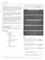 2
2
-
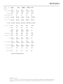 3
3
-
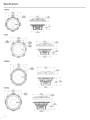 4
4
-
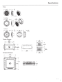 5
5
-
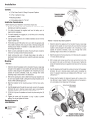 6
6
-
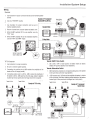 7
7
-
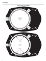 8
8
-
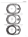 9
9
-
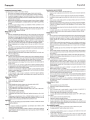 10
10
-
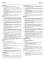 11
11
-
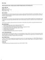 12
12
-
 13
13


Rockford Fosgate T1 T-S Installation & Operation Manual
- Categoria
- Altoparlanti
- Tipo
- Installation & Operation Manual
in altre lingue
- English: Rockford Fosgate T1 T-S
- français: Rockford Fosgate T1 T-S
- español: Rockford Fosgate T1 T-S
- Deutsch: Rockford Fosgate T1 T-S
Documenti correlati
-
Rockford Fosgate T165-S Installation & Operation Manual
-
 Rockford Fosgate Punch P162S Manuale utente
-
 Rockford Fosgate T3652-S Installation & Operation Manual
-
Rockford Fosgate power T252-S Installation & Operation Manual
-
 Rockford Fosgate PUNCH PM2T-S Installation & Operation Manual
-
 Rockford Fosgate T4652-S Installation & Operation Manual
-
Rockford Fosgate PM282HW-B Manuale utente
-
 Rockford Fosgate P152-S Manuale utente
-
Rockford Fosgate R152-S Manuale utente
-
 Rockford Fosgate Punch PP8-T Installation & Operation Manual