
Active Servo
Technology
EJECT
DOLBY B NR
EJECT
Active Servo
Technology
Active Servo
Technology
1
PLAYBACK
2
REC/PLAYBACK
DISC CHANGE
Active Servo
Technology
DISC
PROGRAM
USER
VOLUME
DOWN UP
MEMORY
UPDOWN
REC/PAUSE
MODE
HOUR MIN
NORMAL
DUBBING
HIGH
MEMORY
TIME ADJ
DOLBY NR
AUTO/MAN’L
TIMER
TIMER REC
MUSIC
POWER
PHONES
PRESET/TUNINGBAND
A/B/C/D/E
RANDOM
REPEAT
EDIT
DISPLAY
CD
INPUT INPUT
TAPE 1/2
START
MODE
FREQ PS/PTY/RT/CT
PTY SEEK
1
2
3
OPEN/CLOSE
MINI COMPONENT SYSTEM
GX
–
7
1
PLAYBACK
2
REC/PLAYBACK
DISC CHANGE
DISC
PROGRAM
USER
VOLUME
DOWN UP
MEMORY
UPDOWN
REC/PAUSE
MODE
HOUR MIN
NORMAL
DUBBING
HIGH
MEMORY
TIME ADJ
DOLBY NR
AUTO/MAN’L
TIMER
TIMER REC
MUSIC
POWER
PHONES
PRESET/TUNINGBAND
A/B/C/D/E
RANDOM
REPEAT
EDIT
DISPLAY
CD
INPUT INPUT
TAPE 1/2
START
MODE
FREQ PS/PTY/RT/CT
PTY SEEK
1
2
3
OPEN/CLOSE
MINI COMPONENT SYSTEM
GX
–
70
EJECT
DOLBY B NR
EJECT
Active Servo
Technology
Active Servo
Technology
Active Servo
Technology
OWNER‘S MANUAL
MODE D‘EMPLOI
Natural Sound Mini Component System
Chaîne Mini de la série “Natural Sound”

22
1 Read Instructions – All the safety and operating
instructions should be read before the unit is operated.
2 Retain Instructions – The safety and operating instructions
should be retained for future reference.
3 Heed Warnings – All warnings on the unit and in the
operating instructions should be adhered to.
4 Follow Instructions – All operating and other instructions
should be followed.
5 Water and Moisture – The unit should not be used near
water – for example, near a bathtub, washbowl, kitchen
sink, laundry tub, in a wet basement, or near a swimming
pool, etc.
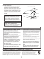
6 Carts and Stands – The unit should be used only with a
cart or stand that is recommended by the manufacturer.
6A A unit and cart combination should be
moved with care. Quick stops,
excessive force, and uneven surfaces
may cause the unit and
cart combination to overturn.
7 Wall or Ceiling Mounting – The unit should be mounted to
a wall or ceiling only as recommended by the
manufacturer.
8 Ventilation – The unit should be situated so that its
location or position does not interfere with its proper
ventilation. For example, the unit should not be situated
on a bed, sofa, rug, or similar surface, that may block the
ventilation openings; or placed in a built-in installation,
such as a bookcase or cabinet that may impede the flow
of air through the ventilation openings.
9 Heat – The unit should be situated away from heat
sources such as radiators, stoves, or other appliances
that produce heat.
10 Power Sources – The unit should be connected to a
power supply only of the type described in the operating
instructions or as marked on the unit.
11 Power-Cord Protection – Power-supply cords should be
routed so that they are not likely to be walked on or
pinched by items placed upon or against them, paying
particular attention to cords at plugs, convenience
receptacles, and the point where they exit from the unit.
12 Cleaning – The unit should be cleaned only as
recommended by the manufacturer.
13 Nonuse Periods – The power cord of the unit should be
unplugged from the outlet when left unused for a long
period of time.
14 Object and Liquid Entry – Care should be taken so that
objects do not fall into and liquids are not spilled into the
inside of the unit.
15 Damage Requiring Service – The unit should be serviced
by qualified service personnel when:
A. The power-supply cord or the plug has been
damaged; or
B. Objects have fallen, or liquid has been spilled into the
unit; or
C. The unit has been exposed to rain; or
D. The unit does not appear to operate normally or
exhibits a marked change in performance; or
E. The unit has been dropped, or the cabinet damaged.
16 Servicing – The user should not attempt to service the unit
beyond those means described in the operating
instructions. All other servicing should be referred to
qualified service personnel.
17 Power Lines – An outdoor antenna should be located
away from power lines.
18 Grounding or Polarization – Precautions should be taken
so that the grounding or polarization is not defeated.
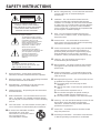
SAFETY INSTRUCTIONS
RISK OF ELECTRIC SHOCK
DO NOT OPEN
CAUTION: TO REDUCE THE RISK OF
ELECTRIC SHOCK, DO NOT REMOVE
COVER (OR BACK). NO USER-SERVICEABLE
PARTS INSIDE. REFER SERVICING TO
QUALIFIED SERVICE PERSONNEL.
The lightning flash with arrowhead
symbol, within an equilateral triangle,
is intended to alert you to the
presence of uninsulated “dangerous
voltage” within the product’s
enclosure that may be of sufficient
magnitude to constitute a risk of
electric shock to persons.
The exclamation point within an
equilateral triangle is intended to alert
you to the presence of important
operating and maintenance
(servicing) instructions in the
literature accompanying the
appliance.
•
Explanation of Graphical Symbols
CAUTION
WARNING
TO REDUCE THE RISK OF FIRE OR
ELECTRIC SHOCK, DO NOT EXPOSE THIS
UNIT TO RAIN OR MOISTURE.

33
1. IMPORTANT NOTICE : DO NOT MODIFY THIS UNIT!
This product, when installed as indicated in the
instructions contained in this manual, meets FCC
requirements. Modifications not expressly approved by
Yamaha may void your authority, granted by the FCC, to
use the product.
2. IMPORTANT : When connecting this product to
accessories and/or another product use only high quality
shielded cables. Cable/s supplied with this product
MUST be used. Follow all installation instructions.
Failure to follow instructions could void your FCC
authorization to use this product in the USA.
3. NOTE : This product has been tested and found to
comply with the requirements listed in FCC Regulations,
Part 15 for Class “B” digital devices. Compliance with
these requirements provides a reasonable level of
assurance that your use of this product in a residential
environment will not result in harmful interference with
other electronic devices.
This equipment generates/uses radio frequencies and, if
not installed and used according to the instructions
found in the users manual, may cause interference
harmful to the operation of other electronic devices.
Compliance with FCC regulations does not guarantee that
interference will not occur in all installations. If this product
is found to be the source of interference, which can be
determined by turning the unit “OFF” and “ON”, please try
to eliminate the problem by using one of the following
measures:
Relocate either this product or the device that is being
affected by the interference.
Utilize power outlets that are on different branch (circuit
breaker or fuse) circuits or install AC line filter/s.
In the case of radio or TV interference, relocate/reorient the
antenna. If the antenna lead-in is 300 ohm ribbon lead,
change the lead-in to coaxial type cable.
If these corrective measures do not produce satisfactory
results, please contact the local retailer authorized to
distribute this type of product. If you can not locate the
appropriate retailer, please contact Yamaha Electronics
Corp., U.S.A. 6660 Orangethorpe Ave, Buena Park, CA
90620.
The above statements apply ONLY to those products
distributed by Yamaha Corporation of America or its
subsidiaries.
Note to CATV system installer:
This reminder is provided to call the CATV system
installer’s attention to Article 820-40 of the NEC that
provides guidelines for proper grounding and, in
particular, specifies that the cable ground shall be
connected to the grounding system of the building, as
close to the point of cable entry as practical.
FCC INFORMATION (for US customers only)
SPECIAL NOTES FOR FCC COMPOSITE
DEVICE (for US customers only)
This device is a composite system. The digital device
component may not cause harmful interference.
19 For US customers only:
Outdoor Antenna Grounding – If an outside antenna is
connected to this unit, be sure the antenna system is
grounded so as to provide some protection against
voltage surges and built-up static charges. Article 810 of
the National Electrical Code, ANSI/NFPA 70, provides
information with regard to proper grounding of the mast
and supporting structure, grounding of the lead-in wire to
an antenna discharge unit, size of grounding conductors,
location of antenna discharge unit, connection to
grounding electrodes, and requirements for the grounding
electrode.
EXAMPLE OF ANTENNA GROUNDING
MAST
GROUND
CLAMP
ANTENNA
LEAD IN
WIRE
ANTENNA
DISCHARGE UNIT
(NEC SECTION 810–20)
GROUNDING CONDUCTORS
(NEC SECTION 810–21)
GROUND CLAMPS
POWER SERVICE GROUNDING
ELECTRODE SYSTEM
(NEC ART 250. PART H)
ELECTRIC
SERVICE
EQUIPMENT
NEC – NATIONAL ELECTRICAL CODE
YAMAHA and the Electronic Industries Association’s
Consumer Electronics Group want you to get the most out of
your equipment by playing it at a safe level. One that lets the
sound come through loud and clear without annoying blaring
or distortion – and, most importantly, without affecting your
sensitive hearing.
Since hearing damage from loud sounds is often
undetectable until it is too late, YAMAHA and the
Electronic Industries Association’s Consumer
Electronics Group recommend you to avoid
prolonged exposure from excessive volume levels.
We Want You Listening For A Lifetime (for US customers only)

44
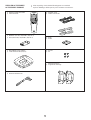
SUPPLIED ACCESSORIES
●
After unpacking, check that the following parts are contained.
ACCESSOIRES FOURNIS
●
Après le déballage, vérifier que les pièces suivantes sont incluses.
●
Remote control transmitter
●
Télécommande
●
Batteries (size AA, UM/SUM-3, R6, HP-7)
●
Piles (format AA, UM/SUM-3, R6, HP-7)
●
AM (MW/LW) loop antenna
●
Cadre-antenne AM (PO/GO)
●
Indoor FM antenna
●
Antenne intérieure FM
●
Speaker cords
●
Câbles d’enceintes
●
Pads
●
Patins
●
Screws
●
Vis
●
Mounting brackets
●
Supports de montage
1
1
2
2
3
3
4
4
5
5
TIME
A
DISC SKIP
PROG
B
TAPE
C
EDIT
D
+I0
E
OPEN
/
CLOSERANDOM
REPEATMODE
6
6
7
7
8
8
9 0
CD
PRESET
TUNER
TAPE
STOP
STOP
PLAY
/
PAUSE
PLAYPLAY
REC
/
PAUSE TAPE 1
/
2
LEVEL MUSIC
TEST FLAT
CENTER
/
REAR
/
DELAY
PROGRAM
USER
POWER
INPUTSLEEP
VOLUME

55
1
PLAYBACK
2
REC/PLAYBACK
EJECT
OPEN/CLOSE
DISC CHANGE
Active Servo
Technology
MINI COMPONENT SYSTEM
GX
–
70
1
2
3
DISC
PROGRAM
USER
VOLUME
DOWN UP
MEMORY
DOWN UP
REC/PAUSE
MODE
HOUR MIN
NORMAL
DUBBING
HIGH
MEMORY
TIME ADJ
DOLBY NR
AUTO/MAN’L
TIMER
TIMER REC
MUSIC
POWER
PHONES
A/B/C/D/E
RANDOM
REPEAT
EDIT
DISPLAY
CD
INPUT INPUT
TAPE 1/2
START
MODE
FREQ PS/PTY/RT/CT
PTY SEEK
EJECT
Active Servo
Technology
MIN MAX
MIC MIC MIXING
2
6
1
4
3
7
8
9 A C0 D E F GB
H I
K
J
L
M
N
O
P
5
F
=
C
896754
3
21
MHz
PRESET
USER
NOR TEST
PHANTOM
TIMER
TAPE 1
SLEEP
STEREO
TUNED MEMORY
AUTO PTY HOLD
PROGRAMMUSIC
ROCK BLUES
RAP JAZZ
PRO LOGIC HALL ARENA
1 2
3 4
100 350 1K 3.5K 10K
VOLUME
ED
3 STEREO
AB
P
R
E
S
E
T
/
T
U
N
I
N
G
/
B
A
N
D
1
Illustration: Europe model
Illustration: Modèle pour l’Europe

66
1
PLAYBACK
2
REC/PLAYBACK
EJECT
OPEN/CLOSE
DISC CHANGE
Active Servo
Technology
MINI COMPONENT SYSTEM
GX
–
70
1
2
3
DISC
PROGRAM
USER
VOLUME
DOWN UP
MEMORY
DOWN
REC/PAUSE
MODE
HOUR MIN
NORMAL
DUBBING
HIGH
MEMORY
TIME ADJ
DOLBY NR
AUTO/MAN’L
TIMER
TIMER REC
MUSIC
POWER
PHONES
PRESET/TUNING/BAND
A/B/C/D/E
RANDOM
REPEAT
EDIT
DISPLAY
CD
TAPE 1/2
START
MODE
FREQ PS/PTY/RT/CT
PTY SEEK
EJECT
UP
Q
R
VST U
W
X
Y
Z
INPUT INPUT
L
H
J
G
TRACK
TOTAL REM
USER
TAPE 1
RANDOM
PROGRAMMUSIC
EDIT
ROCK
ARENA
100 350 1K 3.5K 10K
PROG
S F REP
VOLUME
OVER 15
1234
78910
13 14 15
5
11
6
12
AB
MNO PQ
I
K
2
Illustration: Europe model
Illustration: Modèle pour l’Europe

77
1
PLAYBACK
2
REC/PLAYBACK
EJECT
OPEN/CLOSE
DISC CHANGE
Active Servo
Technology
MINI COMPONENT SYSTEM
GX
–
70
1
2
3
DISC
PROGRAM
USER
VOLUME
DOWN UP
MEMORY
DOWN
REC/PAUSE
MODE
HOUR MIN
NORMAL
DUBBING
HIGH
MEMORY
TIME ADJ
DOLBY NR
AUTO/MAN’L
TIMER
TIMER REC
MUSIC
POWER
PHONES
PRESET/TUNING/BAND
A/B/C/D/E
RANDOM
REPEAT
EDIT
DISPLAY
CD
TAPE 1/2
START
MODE
FREQ PS/PTY/RT/CT
PTY SEEK
EJECT
UP
INPUT INPUT
[
\
]
^abcde
h
g
f
Y
X
STU
VW
R
USER
REC
TAPE 1 2
DUBBING
NOR HIGH
PROGRAMMUSIC
ROCK
ARENA
100 350 1K 3.5K 10K
VOLUME
OVER 15
1234
78910
13 14 15
5
11
6
12
B
3
Illustration: Europe model
Illustration: Modèle pour l’Europe

88
Active Servo
Technology
Active Servo
Technology
4
ij
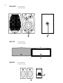
Front speakers
Enceintes avant
NX-GX70
Center speaker
Enceinte centrale
NX-C70
Rear speakers
Enceintes arrière
NX-E70
j

99
TAPE
STOP PLAYPLAY
REC
/
PAUSE TAPE 1
/
2
LEVEL MUSIC
TEST FLAT
CENTER
/
REAR
/
DELAY
PROGRAM
USER
POWER
INPUTSLEEP
VOLUME
Y
T
UVWX
1
1
2
2
3
3
4
4
5
5
TIME
A
DISC SKIP
PROG
B
TAPE
C
EDIT
D
+I0
E
OPEN
/
CLOSERANDOM
REPEATMODE
6
6
7
7
8
8
9 0
CD
PRESET
TUNER
STOP
PLAY
/
PAUSE
S
R
H
G
I
J
Q
KL M N O P
1
1
2
2
3
3
4
4
5
5
TIME
A
DISC SKIP
PROG
B
TAPE
C
EDIT
D
+I0
E
OPEN
/
CLOSERANDOM
REPEATMODE
6
6
7
7
8
8
9 0
CD
PRESET
TUNER
TAPE
STOP
STOP
PLAY
/
PAUSE
PLAYPLAY
REC
/
PAUSE TAPE 1
/
2
LEVEL MUSIC
TEST FLAT
CENTER
/
REAR
/
DELAY
PROGRAM
USER
POWER
INPUTSLEEP
VOLUME
F
E
D
C
B
A
0
9
8
7
6
5
4
3
2
1
5
1
3
2
6
Active Servo
Technology
Active Servo
Technology
1
PLAYBACK
2
REC/PLAYBACK
EJECT
OPEN/CLOSE
DISC CHANGE
Active Servo
Technology
1
2
3
DISC
PROGRAM
USER
VOLUME
DOWN UP
MEMORY
DOWN UP
REC/PAUSE
MODE
HOUR MIN
NORMAL
DUBBING
HIGH
MEMORY
TIME ADJ
DOLBY NR
AUTO/MAN’L
TIMER
TIMER REC
MUSIC
POWER
PHONES
P
R
E
S
E
T
/T
U
N
IN
G
/B
A
N
D
A
/B
/C
/D
/E
RANDOM
REPEAT
EDIT
DISPLAY
CD
INPUT INPUT
TAPE 1/2
S
T
A
R
T
MODE
F
R
E
Q
P
S
/P
T
Y
/R
T
/C
T
PTY SEEK
EJECT
MINI COMPONENT SYSTEM
GX
–
70
0.2 m – 6 m
(8” – 20’)
30°
30°
7

FRONT
SPEAKERS
DO NOT CONNECT THIS UNIT TO SPEAKERS OTHER
THAN NX-C70 (CENTER) OR NX-E70 (REAR).
RL
R L
RL
SINCE THIS UNIT
HAS AN ACTIVE
SERVO CIRCUIT
BUILT–IN.
DO NOT CONNECT
IT TO SPEAKERS
OTHER THAN
NX–GX70.
REAR CENTER REAR
SPEAKERS
CENTER/REAR
OUT
IN
VCR
LD/TV
OUT
MD/AUX
IN
AUDIO SIGNAL
OUT
SUBWOOFER VIDEO SIGNAL
MONITOR
OUT
L
R
R
L
POWER HIGH CUT VOLUME
140 Hz
010
40 Hz
1100
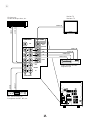
8
Rear speakers
Enceintes arrière
Center speaker
Enceinte centrale
Subwoofer system
Subwoofer de Traitement
Front speakers
Enceintes avant

ANTENNA
FRONT
SPEAKERS
DO NOT CONNECT THIS UNIT TO SPEAKERS OTHER
THAN NX-C70 (CENTER) OR NX-E70 (REAR).
RL
R L
RL
SINCE THIS UNIT
HAS AN ACTIVE
SERVO CIRCUIT
BUILT–IN.
DO NOT CONNECT
IT TO SPEAKERS
OTHER THAN
NX–GX70.
75Ω UNBAL.
REAR CENTER REAR
FM GND AM
CENTER MODE
NORMAL
PHANTOM
SPEAKERS
CENTER/REAR
OUT
IN
VCR
LD/TV
OUT
MD/AUX
IN
AUDIO SIGNAL
OUT
SUBWOOFER VIDEO SIGNAL
MONITOR
OUT
RL
OUT
IN
VCR
LD/TV
OUT
MD/AUX
IN
AUDIO SIGNAL
OUT
SUBWOOFER VIDEO SIGNAL
MONITOR
OUT
VIDEO IN
VIDEO IN
AUDIO IN
VIDEO OUT
AUDIO OUT
LINE OUT
LINE IN
AUDIO OUT
VIDEO OUT
1111
9
LD player etc.
Lecteur de disque laser, etc.
Monitor TV
Moniteur TV
DAT, MD recorder, etc.
Enregistreur de DAT, MD, etc
Video cassette recorder
Magnétoscope

1122
ANTENNA
FRONT
SPEAKERS
DO NOT CONNECT THIS UNIT TO SPEAKERS OTHER
THAN NX-C70 (CENTER) OR NX-E70 (REAR).
RL
R L
RL
SINCE THIS UNIT
HAS AN ACTIVE
SERVO CIRCUIT
BUILT–IN.
DO NOT CONNECT
IT TO SPEAKERS
OTHER THAN
NX–GX70.
75Ω UNBAL.
REAR CENTER REAR
FM GND AM
CENTER MODE
NORMAL
PHANTOM
SPEAKERS
CENTER/REAR
OUT
IN
VCR
LD/TV
OUT
MD/AUX
IN
AUDIO SIGNAL
OUT
SUBWOOFER VIDEO SIGNAL
MONITOR
OUT
@
DISPLAY
MEMORY
TIME ADJ
HOUR
MIN
MEMORY
TIME ADJ
1
2
3
Changes.
Change
verändert sich
Ändras
Cambia
Cambia
Verandert.
Changes.
Change
verändert sich
Ändras
Cambia
Cambia
Verandert.
D
1
PLAYBACK
2
REC/PLAYBACK
EJECT
OPEN/CLOSE
DISC CHANGE
Active Servo
Technology
1
2
3
DISC
PROGRAM
USER
VOLUME
DOWN UP
MEMORY
DOWN UP
REC/PAUSE
MODE
HOUR MIN
NORMAL
DUBBING
HIGH
MEMORY
TIME ADJ
DOLBY NR
AUTO/MAN’L
TIMER
TIMER REC
MUSIC
POWER
PHONES
PRESET/TUNING/BAND
A/B/C/D/E
RANDOM
REPEAT
EDIT
DISPLAY
CD
INPUT INPUT
TAPE 1/2
START
MODE
FREQ PS/PTY/RT/CT
PTY SEEK
EJECT
MINI COMPONENT SYSTEM
GX
–
70
TAPE
STOP PLAYPLAY
REC
/
PAUSE TAPE 1
/
2
LEVEL MUSIC
TEST FLAT
CENTER
/
REAR
/
DELAY
PROGRAM
USER
POWER
INPUTSLEEP
VOLUME
C
To AC outlet
Vers la prise c.a.
1
PLAYBACK
2
REC/PLAYBACK
EJECT
OPEN/CLOSE
DISC CHANGE
Active Servo
Technology
1
2
3
DISC
PROGRAM
USER
VOLUME
DOWN UP
MEMORY
DOWN UP
REC/PAUSE
MODE
HOUR MIN
NORMAL
DUBBING
HIGH
MEMORY
TIME ADJ
DOLBY NR
AUTO/MAN’L
TIMER
TIMER REC
MUSIC
POWER
PHONES
PRESET/TUNING/BAND
A/B/C/D/E
RANDOM
REPEAT
EDIT
DISPLAY
CD
INPUT INPUT
TAPE 1/2
START
MODE
FREQ PS/PTY/RT/CT
PTY SEEK
EJECT
MINI COMPONENT SYSTEM
GX
–
70
PHONES
B
A

E-1
English
ENGLISH
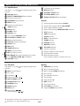
INTRODUCTION
CONTENTS
Page
PRECAUTIONS..................................................................2-3
FEATURES.........................................................................4-5
NAMES OF CONTROLS AND INDICATORS....................6-7
REMOTE CONTROL TRANSMITTER...............................7-8
SETTING UP THE MAIN UNIT..............................................8
SETTING UP THE SPEAKERS........................................9-11
CONNECTIONS..............................................................11-13
REMOVING THE FRONT GRILLES OF FRONT
SPEAKERS..........................................................................13
LISTENING WITH HEADPHONES......................................13
TURNING THE POWER ON/OFF TO THIS SYSTEM.........13
SETTING THE CLOCK........................................................14
ADJUSTING BRIGHTNESS OF THE DISPLAY.................14
VOLUME CONTROL...........................................................14
SPEAKER BALANCE ADJUSTMENT...........................15-16
COMPACT DISC PLAYER OPERATION ......................17-23
TUNING OPERATION....................................................24-26
Page
RECEIVING RDS STATIONS
(U.K. and Europe models only)....................................27-30
TAPE DECK OPERATION ............................................31-34
RECORDING COMPACT DISCS...................................35-40
OTHER RECORDINGS..................................................41-42
OPERATING EXTERNAL UNITS
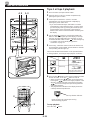
CONNECTED WITH THIS SYSTEM ...................................43
USING GRAPHIC EQUALIZER .....................................44-45
USING SOUND FIELD PROCESSOR ...........................46-49
STORING YOUR OWN PROGRAMS..................................50
KARAOKE OPERATION (Australia, China, Singapore
and General models only) .................................................51
HOW TO USE THE BUILT-IN TIMER............................52-55
MAINTENANCE...................................................................56
TROUBLESHOOTING....................................................56-57
SPECIFICATIONS..........................................................58-59
Thank you for purchasing this YAMAHA product. We hope it will give you many years of trouble-free enjoyment. For the best
performance, read this manual carefully. It will guide you in operating your YAMAHA product.
For basic source play, the following illustrations on top of
pages will help you to look for the section you need.
......CD playback ......Tuning
......Tape playback/recording

E-2
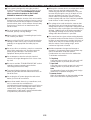
PRECAUTIONS: READ THIS BEFORE OPERATING YOUR UNIT
■ Although the cassette deck’s record/playback heads
used in this unit are high quality heads with
outstanding reproduction characteristics, they can
become dirty through the use of old tapes or from
dust accumulation over time. This can have a
serious effect on reproduction quality. Clean the
heads regularly with one of the commonly available
head cleaners or with cleaning solutions.
■ The voltage to be used must be the same as that
specified on this unit. Using this unit with a higher
voltage than that which is specified is dangerous and
may result in a fire or other type of accident causing
damage. YAMAHA will not be held responsible for
any damage resulting from use of this unit with a
voltage other than that which is specified.
■ The sound level at a given volume setting depends
on speaker location and other factors. Care should
be taken to avoid exposure to sudden high levels of
sound, which may occur when turning on the unit
with the volume control setting at high, and to
continuous high levels of sound.
■ Sudden temperature changes and storage or
operation in an extremely humid environment may
cause condensation inside the cabinet.
Condensation can cause the unit to malfunction.
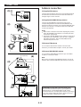
To eliminate condensation:
•
CD pickup
Leave the power on with no disc in the unit until
normal playback is possible (about 1 hour).
•
Tape head
Leave the power on with no tape in the unit until
normal playback is possible (about 1 hour).
Note
If condensation forms on the tape head, foreign
matter may accumulate during use.
•
Remote control
Wipe off condensation on the transmitter window
with a soft cloth before operating the unit.
■ This system is designed for using the provided
Active Servo Processing Speaker System for front
speakers. Therefore, do not attempt to connect
other conventional speakers to the FRONT
SPEAKERS terminals of this system.
■ Choose the installation location of this unit carefully.
Avoid placing it in direct sunlight or close to a source
of heat. Also avoid locations subject to vibration and
excessive dust, heat, cold or moisture. Keep it away
from sources of hum such as transformers and
electric motors.
■ Do not operate this unit upside-down. It may
overheat, possibly causing damage.
■ Never open the cabinet. If something drops into the
set, contact your dealer.
■ Always set the VOLUME control to minimum before
starting an audio source play: increase the volume
gradually to an appropriate level after play has
started.
■ Do not use force on switches, controls or connection
wires. When moving the unit, first disconnect the
power plug and the wires connected to other
equipment. Never pull the wire itself.
■ Do not attempt to clean the unit with chemical
solvents; this might damage the finish. Use a clean,
dry cloth.
■ Be sure to read the “TROUBLESHOOTING” section
regarding common operating errors before
concluding that the unit is faulty.
■ To prevent lightning damage, disconnect the AC
power plug and the antenna cable when there is an
electrical storm.
■ Do not plug the AC power plug to the wall socket
before you finish all connections.
■ Never allow metallic items (e.g. screwdrivers, tools,
etc.) to come near the cassette deck’s
record/playback head assembly in this unit. Doing so
may not only scratch or damage the head’s mirror-
smooth finish, it may change the magnetic
characteristics of the heads, causing a deterioration
in reproduction performance quality.

E-3
English
NOTE
Please check the copyright laws in your country to
record from records, compact discs, radio, etc.
Recording of copyright material may infringe
copyright laws.
IMPORTANT
Please record the serial number of this unit in the
space below.
Serial No.:
The serial number is located on the rear of the unit.
Retain this Owner’s Manual in a safe place for future
reference.
WARNING
TO REDUCE THE RISK OF FIRE OR ELECTRIC
SHOCK, DO NOT EXPOSE THIS APPLIANCE TO
RAIN OR MOISTURE.
CAUTION (FOR CANADA MODEL)
TO PREVENT ELECTRIC SHOCK, MATCH WIDE
BLADE OF PLUG TO WIDE SLOT AND FULLY
INSERT.
FOR CANADIAN CUSTOMER
THIS CLASS B DIGITAL APPARATUS MEETS ALL
REQUIREMENTS OF THE CANADIAN
INTERFERENCE-CAUSING EQUIPMENT
REGULATIONS.
CAUTION FOR CARRYING THIS UNIT
Be sure not to carry or tip this unit with discs
remaining in it.
CAUTION FOR MOVING THIS UNIT
Before moving this unit, first remove all discs from
the disc table and close the table by pressing the
OPEN/CLOSE button. After you confirm that “NO
DISC” lights up on the display, switch off the power
by pressing the POWER switch, and then disconnect
the power plug from the AC outlet.
PRECAUTIONS: READ THIS BEFORE OPERATING YOUR UNIT
The apparatus is not disconnected from the AC
power source as long as it is connected to the wall
outlet, even if the apparatus itself is turned off.
CAUTION
Use of controls or adjustments or performance of
procedures other than those specified herein may
result in hazardous radiation exposure.
DANGER
Invisible laser radiation when open and interlock
failed or defeated.
Avoid direct exposure to beam.
WARNING
As the laser beam used in this unit is harmful to the
eyes, do not attempt to disassemble the cabinet. Refer
servicing to qualified personnel only.
To avoid electrical shock, do not open the cabinet.
Refer servicing to qualified personnel only.
DANGER: The use of optical instrument with this
product will increase eye hazard.
Laser Diode Properties
•
Material: GaAlAs
•
Wavelength: 780nm
•
Emission Duration: continuous
•
Laser Output: max. 44.6µW*
* This output is the value measured at a distance of
about 200mm from the objective lens surface on
the Optical Pick-up Block.

E-4
FEATURES
The System
● 5 Speaker Multi-Channel Audio
System Including Two Front
Speakers, One Center Speaker and
Two Rear Speakers
● Active Servo Processing Front
Speaker System
(NX-GX70)
● Free-Standing/Wall Mounting Type
Rear Speaker System (NX-E70)
● Remote Control Capability
Amplifier
● Minimum RMS Output Power per
Channel
Front L, R: 65W + 65W (6Ω) RMS
Output
Power, 1% THD,
1 kHz
Center
: 20W (6Ω) RMS Output
Power, 1% THD, 1 kHz
Rear: 20W (6Ω) RMS Output
Power, 1% THD, 1 kHz
● Adjustable Display Brightness
● 2 Microphone Jacks and Mic Mixing
Level Control for Karaoke (Australia,
China, Singapore and General Models
Only)
● Multi-Use Timer/Sleep Timer
● Automatic Power-Off Function
● 4 External Audio/Video Component
Connecting Capability
● SUBWOOFER Output Terminal Which
Passes Low Frequencies Only
Compact Disc Player
● 3-Disc Carousel Type CD Changer
● CD Window to Make CD Playback
Visible from Outside
● PLAYXCHANGE; Disc Changing
Capability while Playing Back
Another
● 20-Track Random Access
Programmable CD Playback
● Single Track/Entire Disc/All Disc
Repeat Play
● Random-sequence Play
● Automatic Synchronized Recording
with CD Playback
● Automatic CD Editing Function for
Recording to Tape
Tape Deck
● Double Cassette Tape Deck with
Automatic Reversing Function
● 2-Speed Tape Dubbing
● Dolby B Type Noise Reduction
System
Tuner
● 40 Station Random Access Preset
Tuning
● 40 Station Automatic Preset Tuning
● Multi-Functions for RDS Broadcast
Reception
(Europe and U.K. models only)

E-5
English
FEATURES
Dolby Pro Logic Surround
This unit employs a Dolby Pro Logic Surround decoder similar
to professional Dolby Stereo decoders used in many movie
theaters. By using the Dolby Pro Logic Surround decoder,
you can experience the dramatic realism and impact of Dolby
Surround movie theater sound in your own home. Dolby Pro
Logic employs a four channel five speaker system. The Pro
Logic Surround system divides the input signal into four
levels: the left and right main channels, the center channel
(used for dialog), and the rear surround sound channels
(used for sound effects, background noise, and other ambient
noises). The center channel allows listeners seated in even
less-than-ideal positions to hear the dialog originating from
the action on the screen while experiencing good stereo
imaging.
Dolby Surround is encoded on the sound track of pre-
recorded video tapes, laser discs, and some TV/cable
broadcasts. When you play a source encoded with Dolby
Surround on this unit, the Dolby Pro Logic Surround decoder
decodes the signal and distributes the surround-sound
effects.
In addition, this unit features a built-in automatic input balance
control. This always assures you the best performance
without manual adjustment.
Manufactured under license from Dolby Laboratories
Licensing Corporation. “Dolby”, the double-D symbol and “Pro
Logic” are trademarks of Dolby Laboratories Licensing
Corporation.
Sound Field Processor Including
Dolby Pro Logic Surround Decoder
● 2 Programs for Dolby Surround
Decoding (DOLBY PRO LOGIC and
DOLBY 3 STEREO)
2 Programs for Sound Field
Processing (HALL and ARENA)
[3-Karaoke Modes for Australia,
China, Singapore and General Models
Only]
● Automatic Input Balance Control for
Dolby Pro Logic Surround
● 2 Center Channel Modes
(NORMAL/PHANTOM)
● Test Tone Generator for Easier
Speaker Balance Adjustment
Graphic Equalizer
● 5-Band Adjustable Graphic Equalizer
● 4 Preset Graphic Equalizer Modes
Selectable According to the Music
Source (ROCK, BLUES, RAP and
JAZZ)
● 4-Sound Field and 4-Equalizer
Control Mode Storing Capability

E-6
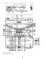
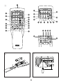
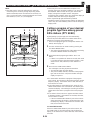
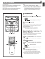
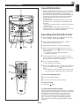
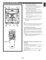
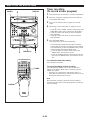
NAMES OF CONTROLS AND INDICATORS
For amplifier/tuner
(See figure 1 on page 55 at the beginning part of this
manual.)
1 A/B/C/D/E Button
2 PRESET/TUNING/BAND Selector Button
3 Remote Control Sensor
4 PROGRAM Selector Button
5 MUSIC Button
6 Equalizer Control Buttons
(ECHO Buttons)
7 USER Button
8 POWER Switch
9 PHONES Jack
0 User Program MEMORY Button
A AUTO/MAN’L (TIMER) Button
B CD Input Selector Button
C TAPE 1/2 Input Selector Button
D HOUR Button
E MIN Button
F TIMER REC Button
G INPUT Selector Buttons
H MIC (Microphone) Jacks
I MIC MIXING (Microphone Mixing) Level Control
J Tuner MEMORY (TIME ADJUST) Button
K VOLUME Control
L (Down)/ (Up) Buttons
M DISPLAY Button
N PTY SEEK START Button
O PTY SEEK MODE Button
P FREQ PS/PTY/RT/CT Selector Button
Display
1 Preset Equalizer Mode Indicator (MUSIC)
2 Sound Field Program Indicator (PROGRAM)
3 User Program Number Indicator
4 Center Channel Mode (NOR/PHANTOM) Indicator
5 TEST Indicator
6 TIMER Set Indicator
7 SLEEP Indicator
8 AUTO Tuning Indicator
9 TUNED Indicator
@ STEREO Indicator
A MEMORY Indicator
B PTY HOLD Indicator
C Volume Level Meter
D Graphic Equalizer Level Indicators
E Preset Number Indicator
F Multi Information Display
(Time, Station Frequency, Volume Level, etc.)
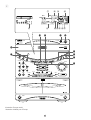
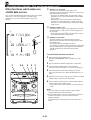
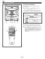
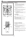
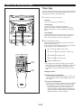
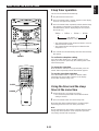
For CD player
(See figure 2 on page 66 at the beginning part of this
manual.)
Q DISC Selector Buttons
R Disc Table
S Stop Button:
T Play/Pause Button: /
U DISC CHANGE Button
V OPEN/CLOSE Button:
W RANDOM Button
X REPEAT Button
Y EDIT Button
Z Skip Buttons: /
(Search Buttons: / )
Display
G RANDOM Play Indicator
H Music Calendar Indicator
I Music Calendar OVER 15 Indicator
J Disc Indicator
K Track Number Indicator
L Time Display
M Play Indicator:
N EDIT Indicator
O Tape Side Indicator
P (S, F) REPEAT Indicator
Q Program (PROG) Play Indicator
*
1
*
2
*
2
*
1
: Provided for Australia, China, Singapore and General Models Only
*
2
: Provided for U.K. and Europe Models Only
*
1

E-7
English
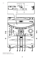
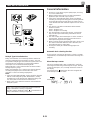
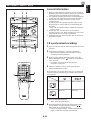
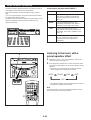
For Tape deck
(See figure 3 on page 77 at the beginning part of this
manual.)
[ Reverse MODE Selector Button
\ DOLBY NR Button
] Deck 1 Cassette Compartment
^ Deck 1 EJECT Button
a Fast Wind Button:
b Stop Button:
c Play Button:
d Fast Wind Button:
e Deck 2 EJECT Button
f Deck 2 Cassette Compartment
g DUBBING (NORMAL/HIGH) Buttons
h REC/PAUSE Button
Display
R DUBBING (NOR/HIGH) Indicator
S Reverse Mode Indicator
T Recording (REC) Indicator
U Tape Number Indicator
V Play Direction Indicator
W Dolby ( ) B NR Indicator
X Tape Number Indicator
Y Tape Counter
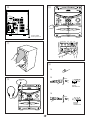
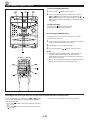
Speakers (Front/Center/Rear)
(See figure 4 on page 88 at the beginning part of this
manual.)
i YST Port
j Speaker Terminals
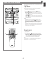
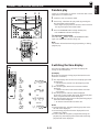
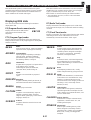
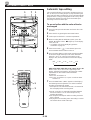
NAMES OF CONTROLS AND INDICATORS
Names of control buttons
(See figure 5 on page 99 at the beginning part of this
manual.)
■
Amplifier/tuner control buttons
1 Remote Control Transmitter Window
2 Preset Station Number Buttons
3 A, B, C, D, E Selector Buttons
4 TEST Button
5 CENTER/REAR/DELAY Selector Button
6 LEVEL Control Buttons
7 SLEEP Button
8 POWER Switch
9 VOLUME – (Down)/+ (Up) Buttons
@ INPUT Selector Button
A USER Button
B PROGRAM Button
C MUSIC Button
D FLAT Button
E TUNER Input Selector Button
F PRESET Number (Down)/ (Up) Buttons
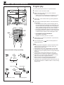
■ CD player control buttons
G Track Number Input Buttons
H TIME Button
I PROGRAM Button
J Disc Play MODE Selector Button
K DISC SKIP Button
L REPEAT Button
M Skip Buttons: /
(Search Buttons: / )
N RANDOM Button
O STOP Button:
P OPEN/CLOSE Button:
Q PLAY/PAUSE Button:
R EDIT Button
S TAPE Button
■
Tape deck control buttons
T REC/PAUSE Button
U TAPE 1/2 Button
V Play Button:
W Stop Button:
X Play Button:
Y Fast Wind Buttons: /
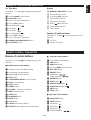
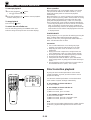
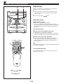
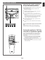
REMOTE CONTROL TRANSMITTER

E-8
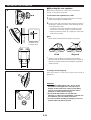
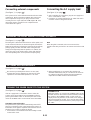
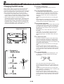
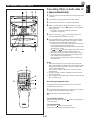
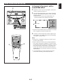
Loading the batteries for the
remote control transmitter
(See figure 6 on page 99.)
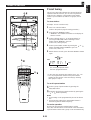
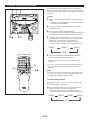
1 Remove the battery compartment cover.
(Slide the cover in the direction of the arrow.)
2 Insert 2 “AA” size batteries (UM/SUM-3, R6, HP-7 or
equivalent) into the battery compartment.
* Installing the batteries improperly may cause failure.
3 Replace the battery compartment cover.
Precautions for battery use
•
Insert the batteries according to the direction indicated in
the battery compartment.
•
Replace all batteries with new ones at the same time.
•
Remove the batteries if they are weak or if the unit is not
in use for long periods.
•
Don’t mix normal batteries with rechargeable batteries.
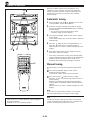
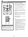
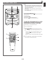
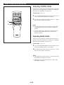
Proper use of the remote control
transmitter
(See figure 7 on page 99.)
Aim (within the range of 60° with no obstacles) the remote
control transmitter at the remote control sensor and operate
as shown.
Notes concerning use
•
Replace the batteries if control distance decreases or
operation becomes unstable.
•
Periodically clean the transmitter window on the remote
control transmitter and the sensor on the main unit with a
soft cloth.
•
Exposing the sensor on the main unit to strong light
(especially an inverter type of fluorescent lamp etc.) may
interfere with operation. In this case, reposition the main
unit to avoid direct lighting.
•
Keep the remote control transmitter away from moisture,
excessive heat, shock and vibrations.
•
The remote control transmitter’s usable range is within
0.2m (8”) and 6m (20’) away from the sensor.
REMOTE CONTROL TRANSMITTER
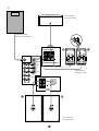
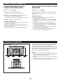
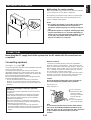
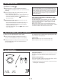
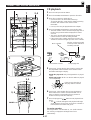
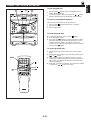
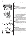
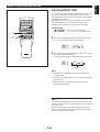
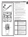
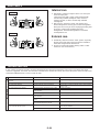
SETTING UP THE MAIN UNIT
1 cm 1 cm
10 cm
10 cm
10 cm
10 cm 10 cm
10 cm
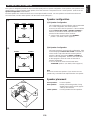
Setup examples
Place the main unit as illustrated on the left and allow spaces
more than indicated around the main unit and more than 10
cm (3-15/16”) behind the main unit to assure good
ventilation. Be sure not to place another unit or any object on
top of the main unit to prevent the ventilation holes on the top
panel of the main unit from being obstructed. Otherwise, it
may cause fire or damage to the main unit.
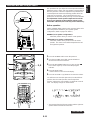
Notes
•
When placing the front speakers apart from the main unit,
allow a space of at least 10 cm (3-15/16”) above, behind
and on the both sides of the main unit.
•
If the main unit is put in a rack, the front of it must be fully
opened.
•
Disconnect the AC supply lead from the AC outlet before
connecting or disconnecting any component.
Main unit
La pagina sta caricando ...
La pagina sta caricando ...
La pagina sta caricando ...
La pagina sta caricando ...
La pagina sta caricando ...
La pagina sta caricando ...
La pagina sta caricando ...
La pagina sta caricando ...
La pagina sta caricando ...
La pagina sta caricando ...
La pagina sta caricando ...
La pagina sta caricando ...
La pagina sta caricando ...
La pagina sta caricando ...
La pagina sta caricando ...
La pagina sta caricando ...
La pagina sta caricando ...
La pagina sta caricando ...
La pagina sta caricando ...
La pagina sta caricando ...
La pagina sta caricando ...
La pagina sta caricando ...
La pagina sta caricando ...
La pagina sta caricando ...
La pagina sta caricando ...
La pagina sta caricando ...
La pagina sta caricando ...
La pagina sta caricando ...
La pagina sta caricando ...
La pagina sta caricando ...
La pagina sta caricando ...
La pagina sta caricando ...
La pagina sta caricando ...
La pagina sta caricando ...
La pagina sta caricando ...
La pagina sta caricando ...
La pagina sta caricando ...
La pagina sta caricando ...
La pagina sta caricando ...
La pagina sta caricando ...
La pagina sta caricando ...
La pagina sta caricando ...
La pagina sta caricando ...
La pagina sta caricando ...
La pagina sta caricando ...
La pagina sta caricando ...
La pagina sta caricando ...
La pagina sta caricando ...
La pagina sta caricando ...
La pagina sta caricando ...
La pagina sta caricando ...
La pagina sta caricando ...
-
 1
1
-
 2
2
-
 3
3
-
 4
4
-
 5
5
-
 6
6
-
 7
7
-
 8
8
-
 9
9
-
 10
10
-
 11
11
-
 12
12
-
 13
13
-
 14
14
-
 15
15
-
 16
16
-
 17
17
-
 18
18
-
 19
19
-
 20
20
-
 21
21
-
 22
22
-
 23
23
-
 24
24
-
 25
25
-
 26
26
-
 27
27
-
 28
28
-
 29
29
-
 30
30
-
 31
31
-
 32
32
-
 33
33
-
 34
34
-
 35
35
-
 36
36
-
 37
37
-
 38
38
-
 39
39
-
 40
40
-
 41
41
-
 42
42
-
 43
43
-
 44
44
-
 45
45
-
 46
46
-
 47
47
-
 48
48
-
 49
49
-
 50
50
-
 51
51
-
 52
52
-
 53
53
-
 54
54
-
 55
55
-
 56
56
-
 57
57
-
 58
58
-
 59
59
-
 60
60
-
 61
61
-
 62
62
-
 63
63
-
 64
64
-
 65
65
-
 66
66
-
 67
67
-
 68
68
-
 69
69
-
 70
70
-
 71
71
-
 72
72


Yamaha GX-70 Manuale utente
- Categoria
- Lettore CD
- Tipo
- Manuale utente
in altre lingue
- English: Yamaha GX-70 User manual
- français: Yamaha GX-70 Manuel utilisateur
- español: Yamaha GX-70 Manual de usuario
- Deutsch: Yamaha GX-70 Benutzerhandbuch
- русский: Yamaha GX-70 Руководство пользователя
- Nederlands: Yamaha GX-70 Handleiding
- português: Yamaha GX-70 Manual do usuário
- dansk: Yamaha GX-70 Brugermanual
- čeština: Yamaha GX-70 Uživatelský manuál
- polski: Yamaha GX-70 Instrukcja obsługi
- svenska: Yamaha GX-70 Användarmanual
- Türkçe: Yamaha GX-70 Kullanım kılavuzu
- suomi: Yamaha GX-70 Ohjekirja
- română: Yamaha GX-70 Manual de utilizare
Documenti correlati
-
Yamaha GX-50RDS Manuale del proprietario
-
-
-
-
-
-
-
-
-