
NORME DI RIFERIMENTO
La conformità con le Direttive Comunitarie:
2014/35/UE (LVD)
2014/30/UE (EMCD)
è dichiarata in riferimento alle seguenti norme armonizzate:
• CEI EN 60669-2-1
3
4
1Manuale d’Uso
INTERRUTTORI CREPUSCOLARI
Leggere attentamente tutte le istruzioni
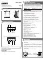
DIMENSIONI
SCHEMI DI COLLEGAMENTO
INSTALLAZIONE
2
Vemer S.p.A.
I - 32032 Feltre (BL) • Via Camp Lonc, 16
Tel +39 0439 80638 • Fax +39 0439 80619
e-mail: info@vemer.it - web site: www.vemer.it
V3IS00920-010
Gli interruttori crepuscolari VELUX e VEREG sono dispositivi di comando
elettronici di interruzione con micro-disconnessione (μ) di apertura fra i
contatti (EN60669-2-1), con soglia di intervento regolabile. VEREG permette
anche la regolazione dell’isteresi e del tempo di intervento.
Codice Modello Descrizione
VJ57030000 Velux Interruttore crepuscolare con 1 regolazione
VJ57110000 Vereg Interruttore crepuscolare con 3 regolazioni
AVVERTENZE DI SICUREZZA
Durante l’installazione ed il funzionamento dello strumento è necessario
rispettare le seguenti indicazioni:
1) Lo strumento deve essere installato da persona qualificata rispettando
scrupolosamente gli schemi di collegamento.
2) Non alimentare il prodotto se qualche parte risulta danneggiata.
3) Lo strumento deve essere installato e messo in funzione in conformità con
la normativa vigente in materia di impianti elettrici.
4) Nell’impianto elettrico dell’edificio in cui lo strumento viene installato va
compreso un interruttore ed un dispositivo di protezione dalle sovracorrenti
5) Non utilizzare lo strumento per scopi diversi da quelli indicati.
6) In caso di malfunzionamento dello strumento non eseguire interventi di
riparazione e contattare direttamente l’assistenza tecnica.
7) Lo strumento può essere utilizzato in ambienti con categoria di
sovratensione III e grado di inquinamento 2.
8) Prima di accedere ai morsetti di collegamento verificare che i conduttori non
siano in tensione.
9) Dopo l’installazione deve essere garantita la inaccessibilità ai morsetti di
collegamento senza l’uso di appositi utensili.
CARATTERISTICHE TECNICHE
• Alimentazione: 230 Vac (-15% ÷ +10%) 50/60 Hz
• Assorbimento: 3VA (0,5W)
• Portata dei contatti: 10 A/250 V~ su carico resistivo
• Tipo di carico:
- Lampade fluorescenti max: 360W/230 V~ (cos ϕ ≥0,8)
- Lampade a incandescenza: max 800 W/230 V~
• Soglia di intervento: 3 ÷ 70 Lux
• Isteresi:
- Velux: 4 Lux non modificabile
- Vereg: 1 ÷ 10 Lux
• Tempo di intervento:
- Velux: 10 secondi non modificabile
- Vereg: 0 ÷ 40 secondi
• Diametro massimo del foro del passacavo per il passaggio dei cavi: 15 mm
• Morsettiera per conduttori con sezione massima dei cavi 1,5 mm²
• Contenitore: resina di policarbonato antischock
• Temperatura di funzionamento: 0 ÷ +50 °C
• Temperatura di immagazzinamento: -10 ÷ +60 °C
• Umidità di funzionamento: 20÷90% non condensante
• Grado di protezione: IP54
• L’installazione può avvenire a parete o a palo (tramite adattatore presente
nella confezione)
• Svitare la vite di blocco e rimuovere la calotta
• Far passare i cavi attraverso il passacavo posto sul lato inferiore e collegare
i cavi dell’alimentazione e del carico, rispettando lo schema di collegamento
• Evitare di installare il dispositivo in luoghi in cui si possono verificare
abbagli o riflessi
• Regolare la soglia di intervento attraverso il trimmer posto sul lato inferiore
(range 3 ÷ 70 lux)
• Regolare l’isteresi con il trimmer P2 e il tempo di intervento con il trimmer
P3 (solo per Vereg)
• Riposizionare la calotta e avvitare la vite di blocco.
VELUX - VEREG
Trimmer per
regolazione soglia
78.6
51.7 41.2
Morsettiera per il
collegamento
dell’alimentazione e
del carico
Passacavo
09-2017
P3 P2
μ
230 V~
50/60 Hz
10
A
/ 250
V~
CARICO
N L
Esempio di collegamento con lampade da 230 V~

REFERENCE STANDARDS
Compliance with Community Directives:
2014/35/EU (LVD)
2014/30/EU (EMCD)
is declared with reference to the following harmonized standards:
• EN 60669-2-1
3
4
1User Manual
TWILIGHT SWITCHES
Read all the instructions carefully
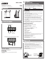
DIMENSIONS
CONNECTION DIAGRAMS
INSTALLATION
2
V3IS00920-010
VELUX - VEREG
The VELUX and VEREG twilight time switches are electronic command
devices containing micro-disconnection (μ) according EN60669-2-1 with
adjustable intervention threshold. VEREG allows also the adjustment of the
hysteresis and of the intervention time.
Code Model Description
VJ57030000 Velux Twilight switch with 1 regulation
VJ57110000 Vereg Twilight switch with 3 regulations
SAFETY WARNINGS
During product installation and operation it is necessary to observe the
following instructions:
1) The instrument must be installed by a qualified person, in strict compliance
with the connection diagrams
2) Do not power the instrument if any part of it is damaged
3) The instrument must be installed and activated in compliance with current
electric system standards
4) Do not use the instrument for purposes different from the one specified.
5) The electrical system in the building in which the instrument is to be
installed should have an over-current switch and a protection device
6) In case of malfunction do not perform repairs and contact immediately the
technical support.
7) The instrument can be used in environments with category of overvoltage III
and pollution degree 2.
8) Before accessing the connection terminals, verify that the leads are not live
9) After installation, inaccessibility to the connection terminals without
appropriate tools must be guaranteed.
TECHNICAL CHARACTERISTICS
• Power supply: 230 Vac (-15% ÷ +10%) 50/60 Hz
• Power absorption: 3VA (0.5W)
• Contact capacity: 10 A/250 V~ on resistant load
• Type load:
-Fluorescent lamps: max 360 W/230 V~ (cos ϕ ≥0.8)
-Incandescent lamps: max 800 W/230 V~
• Intervention threshold 3 ÷ 70 Lux
• Hysteresis:
-Velux: 4 Lux uneditable
-Vereg: 1 ÷ 10 Lux
• Intervention time:
-Velux: 10 seconds uneditable
-Vereg: 0 ÷ 40 seconds
• Maximum diameter of the cable grommet hole for the cables passage: 15 mm
• Terminal block for conductors with maximum cables section: 1.5 mm²
• Container: shockproof polycarbonate resin
• Operating temperature: 0 ÷ +50 °C
• Storage temperature: -10 ÷ +60 °C
Operating humidity: 20 ÷ 90% non condensing
Protection degree: IP54
78.6
51.7 41.2
• Installation can be wall or pole ( by using the adapter in the package)
• Unscrew the screw and remove the cover
• Pass the cables through the cable grommet on the bottom side and connect
the power and the load cables respecting the wiring diagram
• Avoid installing the device in places where dazzle or glare may occur
• Adjust the intervention threshold by the trimmer placed on the bottom side
(range 3 ÷ 70 lux)
• Adjust the hysteresis with the trimmer P2 and the intervention time with the
trimmer P3 (only Vereg)
• Reposition the cover and screw the lock screw
Vemer S.p.A.
I - 32032 Feltre (BL) • Via Camp Lonc, 16
Tel +39 0439 80638 • Fax +39 0439 80619
e-mail: info@vemer.it - web site: www.vemer.it
Trimmer for
threshold
adjustment
Terminal block for
the connection of
the power supply
and the load
Cable grommet
09-2017
P3 P2
μ
230 V~
50/60 Hz
10
A
/ 250
V~
LOAD
N L
Example of connection with 230 V~ lamps
-
 1
1
-
 2
2


in altre lingue
- English: Vemer Velux User manual
Documenti correlati
-
Vemer Quicklux-3F Manuale utente
-
-
-
-
-
Vemer Nana Manuale utente
-
-
Vemer Set Thalos RF Bianco Manuale utente
-
-