Schmalz DUE-SET-8xDYN-M16x125/25-ST-VZ Assembly Instructions
- Tipo
- Assembly Instructions

fischerwerke GmbH & Co. KG
Klaus-Fischer-Straße 1 · 72178 Waldachtal · Germany
Tel. +49 7443 12 – 0
Fax +49 7443 12 – 4222
www.fischer.de
fischer S.A.S
12, Rue Livio · B.P. 10182
67022 Strasbourg-Cedex 1 · France
Tel. +33 388 391867
Fax +33 388 398044
fischer Cobemabel snc
Schaliënhoevedreef 20D
2800 Mechelen · Belgium
Tel. +32 15 28 47 00
Fax +32 15 28 47 10
fischer Benelux B.V.
Amsterdamsestraatweg 45 B/C
1411 AX Naarden · Nederlands
Tel. +31 35 6956666
Fax +31 35 6956699
1) Unterfütterung nach Vorgabe der J. Schmalz GmbH
1) Calage selon préconisations de la société J. Schmalz GmbH
1)
Ondersabelen van het aanbouwdeel volgens opgave van J. Schmalz GmbH
1) Relleno interior según las indicaciones dadas por J. Schmalz GmbH
2) Nach Vorgabe der J. Schmalz GmbH
2) Selon préconisations de la société J. Schmalz GmbH
2) Volgens opgave van J. Schmalz GmbH
2) Según las indicaciones dadas por J. Schmalz GmbH
fischer Highbond-Injektions-Mörtel
FIS HB 150 C, Art. No. 519665
fischer Ibėrica S.A.
C/Klaus Fischer,1
E-43300 Mont-roig del Camp /Tarragona
Tel. +34 977 68387 11
Fax +34 977 8387 70
DEUTSCH
3. Bedienungsanleitung Injektionsmörtel FIS HB:
Verschlusskappe abschrauben. Statikmischer aufschrauben. Einsetzen der Injektionskartusche in eine Auspresspistole
(fischer Kartuschenpistole KPM2), so dass die Skala sichtbar ist. Mörtel so lange auspressen, bis der austretende
Mörtel gleichmäßig grau gefärbt ist.
Nicht grau gefärbter Mörtel bindet nicht ab und ist zu verwerfen.
Montageanleitung
für J. Schmalz GmbH
fischer Highbond-Anker dynamic
FHB dyn
Bestehend aus:
fischer Highbond-Injektionsmörtel FIS HB 150 C
fischer Highbond-Ankerstange FHB-A dyn
Die fischer Highbond-Ankerstange FHB-A dyn darf nur in Verbindung mit dem
fischer Injektionsmörtel FIS HB 150 C verarbeitet werden.
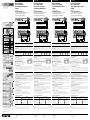
Bestandteile der fischer Highbond-Ankerstange FHB-A dyn
Ankerstange
Zentrierbuchse aus Kunststoff
Kegelpfanne DIN 6319
Kugelscheibe DIN 6319
Sechskantmutter
Sicherungsmutter DIN 7967
hef
tfix
ho
td
Tinst
do df
1)
Montagekennwerte
Achtung:
Nach Überschreiten der Offenzeit (Arbeiten mit Unterbrechungen), neuen Statikmischer ver wenden.
Falls in der Kartuschenöffnung verkrusteter Injektionsmörtel vorhanden ist, diesen vorher entfernen.
Verankerung nur in Durchsteckmontage.
1. Bohrlocherstellung:
Kransäule ausrichten und Befestigung Wandschwenkkran
♦ siehe Bedienungsanleitung Schwenkkrane.
Empfohlene Anordnung der Unterlegbleche übereinander.
Bohrtiefe durch Klebeband am Bohrer markieren ♦ siehe Tabelle.
Die Bohrlochtiefe ist exakt einzuhalten.
Mit Hammerbohrer zylindrisches Bohrloch durch die Fußplatte erstellen.
Absaugung des Bohr mehls durch Staubsauger durchführen.
Eine Verankerung in Vorsteckmontage ist nicht möglich.
2. Bohrloch gründlich reinigen:
Vom Bohrlochgrund mind. 2 x ausblasen, 2 x bürsten und erneut 2 x ausblasen. Das Bürsten erfolgt mit der mitgelieferten
Bürste. Beim Ausblasen ist nur ölfreie Druckluft zulässig. Einstellen der Dübel, dass Gewinde ca. 2 mm über der
Kontermutter sichtbar ist. Probeeinstecken der Dübel in jeder Bohrung. Falls der Dübel noch nicht richtig gesetzt werden
kann, ist ein Nachbohren mit anschließender erneuter Reinigung erforderlich. Alle Dübel entfernen.
Ankerstangen-
Abmessung
Ge-
winde
Veranker-
ungstiefe
Nutzlänge
min. – max.
Bohr-ø Bohrtiefe Bohrtiefe
durch
Anbauteil
Bohr-ø
im
Anbauteil
Montage-
drehmo-
ment
Schlüssel-
weite
Füllmenge
(Skalenteile
auf Kartusche)
Bürste
hef tfix d0h0tddfTinst SW SkBS
[mm] [mm] [mm] [mm] [mm] [mm] [Nm] - - ø
FHB-A dyn 12x100 /25 M12 100 8–25 14 130–tfix 130 2) 40 19 7 14
FHB-A dyn 12x100 /75 M12 100 8–75 14 180–tfix 180 2) 40 19 12 14
FHB-A dyn 12x100 /100 M12 100 8–100 14 205–tfix 205 2) 40 19 13 14
FHB-A dyn 12x100 /140 M12 100 8–140 14 245–tfix 245 2) 40 19 15 14
FHB-A dyn 16x125 /25 M16 125 10–25 18 155–tfix 155 2) 60 24 9 16/18
FHB-A dyn 16x125 /50 M16 125 10–50 18 180–tfix 180 2) 60 24 10 16/18
Ungenügende Reinigung = verminderte Tragfähigkeit
Bei Verwendung von Hohlbohrern mit Absaugung ist keine Bohrlochreinigung erforderlich.
4. Bohrlochverfüllung
Die Bohrlochverfüllung muss durch die Dübeldurchgangsbohrung in der Fußplatte erfolgen.Injektionsmörtel vom
Bohrlochgrund ausgehend hubweise verfüllen. Füllmenge siehe Tabelle oben.
Die Füllmenge ist exakt einzuhalten.
5. Ankerstangen setzen
Unmittelbar anschließend Highbond-Ankerstange FHB dyn komplettiert mit Sicherungsmutter, Sechskantmutter,
Kegelpfanne (Unterlegscheibe) und Zentrierbuchse unter geringer Dreh bewe gung bis zur Setztiefe eindrücken.
Die Setztiefe ist erreicht, wenn die Unterlegscheibe vollflächig an der Fußplatte anliegt und die Zentrierbuchse in die
Durchgangsbohrung komplett eindringt.
6. Verarbeitungs- und Aushärtezeit
Die Ankerstange muss innerhalb der Verarbeitungszeit des Injektionsmörtels eingesteckt sein.
Die Aushärtzeit abwarten. Fußplatte mit vorgegebenem Montagedrehmoment auf die Sechs kant mutter befestigen.
Sicherungsmutter handfest aufschrauben und mit Schraubenschlüssel ¼ bis ½ Umdrehung anziehen.
Wartezeiten bis zum Aufbringen der Last3)
Temperatur im Verankerungsgrund4) Wartezeit in Minuten
trockener Verankerungsgrund feuchter Verankerungsgrund
– 5 °C — ± 0 °C 360 720
> ± 0 °C — + 5 °C 180 360
> + 5 °C — + 10 °C 90 180
> + 10 °C — + 20 °C 35 70
> + 20 °C — + 30 °C 20 40
> + 30 °C — + 40 °C 12 25
3) Die Verarbeitungstemperatur des Mörtels muss mindestens + 5°C betragen.
4) Die Temperatur im Verankerungsgrund darf während der Aushärtung – 5 °C nicht unterschreiten.
FRANÇAIS
3. Conseils d’utilisation du mortier d’injection FIS HB :
Dévisser le capuchon. Visser le mélangeur statique. Placer la cartouche de mortier dans un pis tolet d’injection (pistolet
à cartouches fischer KPM2) de manière à ce que la graduation soit visible. Presser le mortier jusqu’à ce que le mortier
sortant soit uniformément teinté en gris.
Le mortier d’injection non teinté en gris ne lie pas et doit être jeté.
Instructions de montage
pour J. Schmalz GmbH
Ancrage fischer pour charges
dynamiques Highbond FHB dyn
Il se compose de :
mortier d’injection Highbond fischer FIS HB 150 C
goujon d’ancrage Highbond fischer FHB-A dyn
Le goujon d’ancrage Highbond fischer FHB-A dyn ne doit être utilisé qu’en
combinaison avec le mortier d’injection fischer FIS HB 150 C.
Composants du goujon d’ancrage Highbond fischer FHB-A dyn
Goujon d’ancrage
Canon de centrage synthétique
Rondelle DIN 6319
Rondelle sphérique DIN 6319
Ecrou six pans
Contre-écrou DIN 7967
hef
tfix
ho
td
Tinst
do df
1)
Caractéristiques de montage
Attention :
Après dépassement du temps de manipulation (travaux avec interruption), il convient de mettre en place un nouvel embout
mélangeur. Retirer les éventuels résidus de mortier durcis présents au niveau de la sortie de la cartouche.
Ancrage uniquement en montage traversant.
1. Mode de perçage :
Aligner la colonne support de grue et fixer la grue à flèche pivotante murale
♦ voir conseils d’utilisation.
Grue pivotante Disposition conseillée des rondelles les unes sur les autres.
Profondeur du perçage par ruban adhésif sur le foret marquer ♦ voir tableau.
La profondeur du perçage doit être respectée avec précision.
Avec un foret à marteau, percer un trou cylindrique au travers de la plaque d’assise.
Aspirer la poussière de perçage à l’aide d’un aspirateur.
L’ancrage n’est pas possible en montage à fleur.
2. Nettoyer soigneusement le trou de perçage :
Purger depuis le fond du trou de perçage min. 2 x, brosser 2 x puis purger à nouveau 2 x. Le brossage s’effectue avec la
brosse livrée. Lors de la purge, seule l’utilisation d’air comprimé non lubrifié est autorisée. Placer la cheville afin que le
filetage soit visible à env. 2 mm au dessus du contre-écrou. Placer la cheville à titre d’essai dans chaque perçage. Si la
cheville ne peut pas encore être placée correctement, un perçage ultérieur avec un nouveau nettoyage est nécessaire. Ôter
toutes les chevilles.
Type de goujon
d’ancrage
File-
tage
Profondeur
d’ancrage
Long. utile
min. – max.
Diamètre
de forage
Profondeur
de forage
Prof. de forage
au travers
de l’élément
à fixer
Diamètre de
forage dans
l’élément
à fixer
Couple de
serrage
Ouverture
de clé
Nombre de
graduation
(nécessaire au
remplissage)
Ecouvillon
adapté
hef tfix d0h0tddfTinst SW SkBS
[mm] [mm] [mm] [mm] [mm] [mm] [Nm] - - ø
FHB-A dyn 12x100 /25 M12 100 8–25 14 130–tfix 130 2) 40 19 7 14
FHB-A dyn 12x100 /75 M12 100 8–75 14 180–tfix 180 2) 40 19 12 14
FHB-A dyn 12x100 /100 M12 100 8–100 14 205–tfix 205 2) 40 19 13 14
FHB-A dyn 12x100 /140 M12 100 8–140 14 245–tfix 245 2) 40 19 15 14
FHB-A dyn 16x125 /25 M16 125 10–25 18 155–tfix 155 2) 60 24 9 16/18
FHB-A dyn 16x125 /50 M16 125 10–50 18 180–tfix 180 2) 60 24 10 16/18
Nettoyage insuffisant = capacités de charge réduites
En cas d‘utilisation de forets creux avec aspiration, il n‘est pas nécessaire de nettoyer le trou de forage.
4. Remplissage du forage
Le remplissage du forage doit être effectué au travers du forage de passage de la cheville dans la plaque d’appui.
Combler avec le mortier d’injection par jets à partir du fond du forage. Quantité de remplissage : voir tableau ci-dessus.
La quantité de remplissage doit être respectée avec précision.
5. Placer les goujons d’ancrage
Ensuite, enfoncer immédiatement le goujon d‘ancrage Highbond FHB dyn complété par le contre-écrou, l’écrou six pans, la
rondelle et la bague de centrage en effectuant un faible mouvement de rotation jusqu’à la profondeur de pose.
La profondeur de pose est atteinte lorsque la rondelle est complètement plaquée sur toute sa surface contre la plaque
d’appui et que la bague de centrage est complètement introduite dans le forage de passage.
6. Temps de traitement et de durcissement
Le goujon d’ancrage doit être introduit pendant le temps de traitement du mortier d’injection. Attendre pendant le temps
de durcissement. Fixer la plaque d’appui à l’écrou six pans avec le couple de rotation du montage indiqué. Visser le contre-
écrou solidement et serrer avec une clé plate ¼ jusqu’à ½ tour.
Temps d’attente jusqu’à l’application de la charge3)
Temperatur dans le fond de l’ancrage4) Temps d’attente en minutes
fond de l’ancrage sec fond de l’ancrage humide
– 5 °C — ± 0 °C 360 720
> ± 0 °C — + 5 °C 180 360
> + 5 °C — + 10 °C 90 180
> + 10 °C — + 20 °C 35 70
> + 20 °C — + 30 °C 20 40
> + 30 °C — + 40 °C 12 25
3) Die Verarbeitungstemperatur des Mörtels muss mindestens + 5°C betragen.
4) Die Temperatur im Verankerungsgrund darf während der Aushärtung – 5 °C nicht unterschreiten.
NEDERLANDS
3. Gebruiksaanwijzing van de Injectiemortel FIS HB:
Schroef de dop los. Schroef de statische menger erop. Plaats de mortelpatronen in een doseer pistool (fischer
patronenpistool KPM2), zodat de schaalverdeling zichtbaar is. Net zo lang mortel uit het pistool drukken, tot de
uittredende mortel een gelijkmatige grijze kleur heeft.
Mortel die niet grijs is, bindt niet en moet worden weggegooid.
Montage-instructies
voor de J. Schmalz GmbH
fischer Highbond-Anker dynamic
FHB dyn
Bestaan uit de volgende delen:
fischer Highbond-Injectiemortel FIS HB 150 C
fischer Highbond ankerstang FHB-A dyn
De fischer Highbond ankerstang FHB-A dyn mag alleen in combinatie met de
fischer Injectiemortel FIS HB 150 C worden gebruikt.
Bestanddelen van de fischer Highbond ankerstang FHB-A dyn
Ankerstang
Centreernaaf uit kunststof
Kraaghuls DIN 6319
Kogelschijf DIN 6319
Zeskant moer
Borgmoer DIN 7967
hef
tfix
ho
td
Tinst
do df
1)
Montagewaarden
Let op:
Na het overschrijden van de verwerkingstijd (werken met onderbrekingen), dienen nieuwe mengtuit gebruikt te worden.
Indien er in de opening van het patroon aangekoekte injectiemortel aanwezig is, dient deze eerst te worden verwijderd.
Verankering alleen in doorsteekmontage.
1. Boren boorgat:
De kraankolom uitlijnen en bevestigen van de wandzwenkkraan
♦ zie de bedieningshandleiding van de kraan.
De aanbevolen plaatsing van de tussenringen is op elkaar.
De boordiepte m.b.v. plakband op de boor aangeven ♦ zie de tabel.
De boordiepte moet exact worden aangehouden.
Maak met behulp van de hamerboor een cilindrisch gat in de voetplaat.
Zuig het boorstof weg met een stofzuiger.
Een verankering door middel van voorsteekmontage is niet mogelijk.
2. Boorgat goed reinigen:
Het boorgat vanaf de onderkant ten minste 2 x uitblazen, 2 x borstelen en nogmaals 2 x uitblazen. Gebruik de meegeleverde
borstel voor het borstelen. Voor het uitblazen is alleen olievrije perslucht toegestaan. Stel de ankerhulzen zo in, dat de
schroefdraad tot ca. 2 mm boven de borgmoer zichtbaar is. Instelling van de ankerhulzen bij ieder boorgat proefondervindelijk
controleren. Als de ankerhuls niet correct kan worden aangebracht, moet worden nageboord en is een hernieuwde reiniging
noodzakelijk. Verwijder alle ankerhulzen.
Ankerstang
afmeting
Draad Ver-
ankerings-
diepte
Gebruiks-
lengte
min. – max.
Boor ø Boordiepte Boordiepte
door de
ankerplaat
Boor ø
in
ankerplaat
Montage-
aandraai-
moment
Sleutel-
breedte
Vulmengsel
(schaalverdeling
op patroon)
Vereiste
borstels
hef tfix d0h0tddfTinst SW SkBS
[mm] [mm] [mm] [mm] [mm] [mm] [Nm] - - ø
FHB-A dyn 12x100 /25 M12 100 8–25 14 130–tfix 130 2) 40 19 7 14
FHB-A dyn 12x100 /75 M12 100 8–75 14 180–tfix 180 2) 40 19 12 14
FHB-A dyn 12x100 /100 M12 100 8–100 14 205–tfix 205 2) 40 19 13 14
FHB-A dyn 12x100 /140 M12 100 8–140 14 245–tfix 245 2) 40 19 15 14
FHB-A dyn 16x125 /25 M16 125 10–25 18 155–tfix 155 2) 60 24 9 16/18
FHB-A dyn 16x125 /50 M16 125 10–50 18 180–tfix 180 2) 60 24 10 16/18
Onvoldoende reiniging = verminderd draagvermogen
Bij gebruik van holle boren met afzuiging is het niet nodig om het boorgat te poetsen.
4. Boorgatvulling
Het boorgat moet via het gat van de ankerhuls in de voetplaat worden gevuld. De injectiemortel slagsgewijs vanaf de
onderkant in het boorgat spuiten. Zie bovenstaande tabel voor de te vullen hoeveelheid.
De te vullen hoeveelheid moet exact worden aangehouden.
5. Ankerstangen aanbrengen
Direct aansluitend de Highbond ankerstang FHB dyn samen met de borgmoer, zeskante moer, conische ring (tussenring) en
centreerbus door voorzichtig draaien tot aan de plaatsingsdiepte indrukken.
De plaatsingsdiepte is bereikt, als de tussenring volledig tegen de voetplaat rust en de centreerbus volledig in het doorga-
ande boorgat zit.
6. Verwerkings- en uithardingstijd
Die Ankerstange muss innerhalb der Verarbeitungszeit des Injektions-Mörtels eingesteckt sein.
Die Aushärtzeit abwarten. Fußplatte mit vorgegebenem Montagedrehmoment auf die Sechs kant mutter befestigen.
Sicherungsmutter handfest aufschrauben und mit Schraubenschlüssel ¼ bis ½ Umdrehung anziehen.
Wachttijden tot het aanbrengen van de last3)
Temperatuur in de verankeringsbasis4) Wachttijd in minuten
droge verankeringsbasis vochtige verankeringsbasis
– 5 °C — ± 0 °C 360 720
> ± 0 °C — + 5 °C 180 360
> + 5 °C — + 10 °C 90 180
> + 10 °C — + 20 °C 35 70
> + 20 °C — + 30 °C 20 40
> + 30 °C — + 40 °C 12 25
3) De verwerkingstemperatuur van de mortel dient ten minste + 5 °C te bedragen.
4) De temperatuur in de verankeringsbasis mag tijdens het uitharden – 5 °C niet onderschrijden.
ESPAÑOL
3. Instrucciones de uso del mortero de inyección FIS HB:
Desatornillar la tapa de cierre. Atornillar la mezcladora estática. Insertar el cartucho de mortero dentro de la pistola
exprimidora fischer KPM2, de forma que sea reconocible la escala. Exprimir, hasta que el mortero emergente tenga un
color gris homogéneo.
El mortero que no es de color gris, no fragua y debe desecharse.
Instrucciones de montaje
para J. Schmalz GmbH
Anclaje Highbond dynamic fischer
FHB dyn
Compuesto por:
Mortero de inyección Highbond fischer FIS HB 150 C
Varilla de anclaje Highbond fischer FHB-A dyn
La varilla de anclaje Highbond fischer FHB-A dyn sólo puede utilizarse en
combinación con el mortero de inyección fischer FIS HB 150 C.
Componentes de la varilla de anclaje Highbond fischer FHB-A dyn
Varilla de anclaje
Casquillo centrador de plástico
Arandela cónica DIN 6319
Arandela esférica DIN 6319
Tuerca hexagonal
Contratuerca DIN 7967
hef
tfix
ho
td
Tinst
do df
1)
Datos de montaje
Atención:
Si se supera el tiempo de trabajabilidad (trabajos con interrupciones), utilizar un boquilla mezcladora nueva.
En el caso de que haya incrustaciones de mortero en la boca del cartucho, éstas deberán eliminarse previamente.
Anclaje sólo en el montaje a través.
1. Ejecución del taladro:
Alinear la columna de la grúa y fijar la grúa giratoria de pared
♦ Ver el manual de servicio de grúas orientables.
Disposición recomendada de las chapas base, una encima de otra.
Marcar la profundidad de percusión mediante una cinta adhesiva que se
coloca en el taladro ♦ ver la tabla.
Debe cumplirse exactamente la profundidad de taladrado.
Realizar un orificio cilíndrico a través de la placa basal, mediante un taladro de percusión.
Eliminar el polvo producido mediante una aspiradora.
No es posible efectuar el anclaje mediante un preposicionado.
2. Limpieza a fondo del taladro:
Soplar como mín. 2 veces mecánicamente desde el fondo del orificio, cepillar 2 veces y volver a soplar 2 veces. Se debe
cepillar con el cepillo suministrado. Al soplar, sólo es permisible usar aire comprimido sin aceite. Ajustar los tacos, de forma
que la rosca sobresalga aprox. 2 mm sobre la contratuerca. Efectuar la prueba de colocar el taco en cada orificio. Si aún no
se pudiera insertar correctamente un taco, es necesario retaladrar y volver a limpiar a continuación. Extraer todos los tacos.
Dimensiones de la
varilla de anclaje
Rosca Prof. de
anclaje
Espesor
máximo
a fijar
min. – max.
Diámetro
de taladro
Prof. de
taladro
Prof. de
taladro
a través de
objeto a fijar
Diámetro de
taladro
en el objeto
a fijar
Par de
apriete
Ancho de
llave
Volumen de
relleno (gradu-
ación de escala
del cartucho)
Escobilla
necesaria
hef tfix d0h0tddfTinst SW SkBS
[mm] [mm] [mm] [mm] [mm] [mm] [Nm] - - ø
FHB-A dyn 12x100 /25 M12 100 8–25 14 130–tfix 130 2) 40 19 7 14
FHB-A dyn 12x100 /75 M12 100 8–75 14 180–tfix 180 2) 40 19 12 14
FHB-A dyn 12x100 /100 M12 100 8–100 14 205–tfix 205 2) 40 19 13 14
FHB-A dyn 12x100 /140 M12 100 8–140 14 245–tfix 245 2) 40 19 15 14
FHB-A dyn 16x125 /25 M16 125 10–25 18 155–tfix 155 2) 60 24 9 16/18
FHB-A dyn 16x125 /50 M16 125 10–50 18 180–tfix 180 2) 60 24 10 16/18
Limpieza insuficiente = menor capacidad de carga
Si se utilizan taladros huecos con succión, no es necesario limpiar el orificio de perforación.
4. Relleno del taladro
Los orificios deben rellenarse a través del orificio de paso del taco de la placa basal. Rellenar el mortero a inyección por
chorros, partiendo desde el fondo del orificio. Ver la tabla anterior de las cantidades a rellenar.
Debe cumplirse exactamente la cantidad a rellenar.
5. Fijar los vástagos de anclaje
Inmediatamente después, completar el vástago de anclaje Highbond FHB dyn con la tuerca de fija ción. Introducir a presión
la tuerca hexagonal, el cojinete cónico (arandela) y el casquillo de centraje hasta la profundidad correspondiente mediante
un ligero giro. La profundidad se ha alcanzado, cuando la arandela queda completamente asentada sobre la placa basal, y
el casquillo de centraje atraviesa completamente el orificio de paso.
6. Tiempo de trabajabilidad y endurecimiento
El vástago de anclaje debe quedar insertado mientras se esté manipulando el mortero de inyec ción.
Esperar a que endurezca. Fijar la placa basal sobre la tuerca hexagonal, con el par de giro de montaje prescrito.
Atornillar la tuerca de fijación a mano, y apretarla de ¼ a ½ vuelta con la llave.
Tiempos de espera antes de aplicar la carga3)
Temperatura en la base de anclaje4) Tiempo de espera en minutos
Base de anclaje seca Base de anclaje húmeda
– 5 °C — ± 0 °C 360 720
> ± 0 °C — + 5 °C 180 360
> + 5 °C — + 10 °C 90 180
> + 10 °C — + 20 °C 35 70
> + 20 °C — + 30 °C 20 40
> + 30 °C — + 40 °C 12 25
3) La temperatura de aplicación del mortero debe ser de + 5 °C como mínimo.
4) La temperatura en la base de anclaje no debe bajar de – 5 °C durante el endurecimiento.
Gewinde M12 M16
Bauteildicke
excl. evtl. vorhandener Ausgleichsschichten ≥ 200 mm 130 – 199 mm ≥ 250 mm 160 – 249 mm
allseitiger Randabstand
(Ränder/Dehnfugen etc.) ≥ 100 mm ≥ 200 mm ≥ 100 mm ≥ 200 mm
Filetage M12 M16
Épaisseur du composant
l‘exclusion des couches de nivellement éventuellement existantes ≥ 200 mm 130 – 199 mm ≥ 250 mm 160 – 249 mm
distance des bords sur tous les côtés
(bords/joints de dilatation, etc.) ≥ 100 mm ≥ 200 mm ≥ 100 mm ≥ 200 mm
Draad M12 M16
Onderdelen dikte
excl. eventueel bestaande levelling lagen ≥ 200 mm 130 – 199 mm ≥ 250 mm 160 – 249 mm
randafstand aan alle zijden
(randen/uitzettingsvoegen etc.) ≥ 100 mm ≥ 200 mm ≥ 100 mm ≥ 200 mm
Rosca M12 M16
El grosor del componente
excl. las posibles capas de nivelación existentes ≥ 200 mm 130 – 199 mm ≥ 250 mm 160 – 249 mm
distancia de los bordes en todos los lados
(bordes/juntas de expansión, etc.) ≥ 100 mm ≥ 200 mm ≥ 100 mm ≥ 200 mm
1
2
3
4
5
6
7
1)
1)
1)
1)
1)
1)
1)
1)
2x
1)
2x
1)
2x
1)

00174242 (2) · 01/2021 [ajm] – Änderungen im Zuge technischer Verbesserungen vorbehalten.
fischer Highbond-Injektions-Mörtel
FIS HB 150 C, Art. No. 519665
fischer fixing (UK) Ltd
Whitely Road · Wallingford, Oxfordshire
OX10 9AT – United Kingdom
Phone +44 1491 827900
Fax +44 1491 827953
fischer italia s.r.l.
Corso Stati Uniti, 25 · Casella Postale 391
35127 Padova – Z. I. Sud · Italia
Tel. +39 049 8063-111
Fax +39 049 8063-395
フィッシャージャパン株式会社
〒102-0074
東京都千代田区九段南 3-4-15 。清新九段ビル 3 階
電話番号 03 3263 4491
ファックス番号 03 6272 9935
1) Underlay in accordance with the requirements of J. Schmalz GmbH
1) Letto di posa conforme alla direttiva di J. Schmalz GmbH
1) まった場合は、事前に取り J. Schmalz GmbH
2) In accordance with the requirements of J. Schmalz GmbH
2) Conforme alla direttiva di J. Schmalz GmbH
2) った場合は、事前に取りい J. Schmalz GmbH
ENGLISH
3. Instructions for using injection mortar FIS HB:
Unscrew screw cap. Screw on static mixer. Place the mortar cartridge in a mastic gun (fischer KPM2 applicator gun) so
that the scale is visible. Press the mortar until the emergent mortar is an even grey colour.
Mortar that is not grey does not bind and should be discarded.
Installation
for J. Schmalz GmbH
fischer highbond anchor dynamic
FHB dyn
Consisting of:
fischer highbond injection mortar FIS HB 150 C
fischer highbond anchor rod FHB-A dyn
The fischer highbond anchor rod FHB-A dyn may only be used in conjunction with fischer injection
mortar FIS HB 150 C.
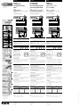
Components of fischer highbond anchor rod FHB-A dyn
Anchor rod
Plastic centring sleeve
Washer DIN 6319
Spherical washer DIN 6319
Hexagonal nut
Lock nut DIN 7967
hef
tfix
ho
td
Tinst
do df
1)
Installation parameters
Please note:
If the open time is exceeded (work with interruptions) use a new static mixer.
If the cartridge opening is encrusted with injection mortar, remove beforehand.
Anchoring only for push-through installations.
1. Drilling the hole:
Align crane post and attach the wall-mounted slewing crane
♦ see operating instructions for slewing cranes.
Recommended layout of shims: on top of each other.
Use tape to mark drilling depth on drill ♦ see table.
The drilling depth is to be exactly adhered to.
Use hammer drill to create a cylindrical drill hole through the base plate.
Use a vacuum cleaner to extract the drill dust.
It is not possible to anchor in pre-installation.
2. Cleaning the drill hole thoroughly:
Blow down, brush and repeat blow down on the drill hole base at least twice. Brush using the brush supplied. Only unoiled
compressed air may be used for blowing down. Position the anchor bolt so that the screw thread is visible approx. 2 mm
above the lock nut. Make sure the anchor bolt fits in each drill hole. If the anchor bolt cannot be positioned properly, the
hole must be drilled and then cleaned again. Remove all anchor bolts.
Anchor rod-
dimensions
Thread Anchoring-
depth
Usable
length
min. – max.
ø
Drill bit
Drilling
depth
Drilling depth
for through
fixings
ø Drill bit
for through
fixings
Installation
torque
Width
across flats
Capacity
(scale divisions
on cartridge)
Brush
hef tfix d0h0tddfTinst SW SkBS
[mm] [mm] [mm] [mm] [mm] [mm] [Nm] - - ø
FHB-A dyn 12x100 /25 M12 100 8–25 14 130–tfix 130 2) 40 19 7 14
FHB-A dyn 12x100 /75 M12 100 8–75 14 180–tfix 180 2) 40 19 12 14
FHB-A dyn 12x100 /100 M12 100 8–100 14 205–tfix 205 2) 40 19 13 14
FHB-A dyn 12x100 /140 M12 100 8–140 14 245–tfix 245 2) 40 19 15 14
FHB-A dyn 16x125 /25 M16 125 10–25 18 155–tfix 155 2) 60 24 9 16/18
FHB-A dyn 16x125 /50 M16 125 10–50 18 180–tfix 180 2) 60 24 10 16/18
Inadequate cleaning = reduced load-carrying capacity
When using hollow drills with suction, there is no need to clean the drill hole required.
4. Filling the drill hole
The drill hole filling must be inserted via the anchor bolt through hole in the base plate. Fill in the injection mortar from the
drill hole base stroke by stroke. For fill quantity see table above.
The fill quantity is to be exactly adhered to.
5. Setting the anchor rod
Use a light circular motion to immediately press in highbond anchor dynamic FHB dyn – complete with lock nut, hexagonal
nut, washer (flat washer) and centring sleeve – up to setting depth. The setting depth has been achieved once the washer
fits fully on to the base plate, and the centring sleeve fully penetrates the through hole.
6. Processing and setting time
The anchor rod must be inserted within the injection mortar processing time. Wait for the setting time. Fit the base plate
onto the hexagonal nut using the prescribed installation torque. Screw on the lock nut so that it is hand-tight, and then use
a screw wrench to screw it through ¼ to ½ rotations.
Waiting periods until applying the load3)
Temperature in anchoring base4) Waiting period in minutes
Dry anchoring base Wet anchoring base
– 5 °C — ± 0 °C 360 720
> ± 0 °C — + 5 °C 180 360
> + 5 °C — + 10 °C 90 180
> + 10 °C — + 20 °C 35 70
> + 20 °C — + 30 °C 20 40
> + 30 °C — + 40 °C 12 25
3) The processing temperature of the mortar must be at least + 5 °C.
4) The temperature in the anchoring base must not fall below – 5 °C during curing.
ITALIANO
Istruzioni di montaggio
per J. Schmalz GmbH
Ancorante fischer Highbond (ad elevato
potere di fissaggio) dinamico FHB dyn
Formato da:
Resina ad iniezione fischer Highbond (ad elevato potere di fissaggio) FIS HB 150 C
Barra di armatura Highbond (ad elevato potere di fissaggio) fischer FHB-A dyn
La barra di armatura Highbond (ad elevato potere di fissaggio) fischer FHB-A dyn deve essere
utilizzata solo in combinazione con resina fischer ad iniezione FIS HB 150 C.
Elementi della barra di armatura fischer Highbond FHB-A dyn
Barra di armatura
Bussola di centratura di materiale sintetico
Siviera conica DIN 6319
Rondella sferica DIN 6319
Vite a testa esagonale
Vite di sicurezza DIN 7967
hef
tfix
ho
td
Tinst
do df
1)
Dati di montaggio
3. Istruzioni per l’uso della resina a iniezione FIS HB:
Svitare il tappo. Avvitare il miscelatore statico. Applicare la cartuccia di resina alla pistola appli catrice (pistola per
cartucce fischer KPM2), in modo che la scala sia visibile. Premere finché non fuoriesce resina color grigio uniforme.
Se non è grigia, la resina non lega e deve essere gettata.
Attenzione:
Una volta scaduto il tempo di apertura (lavoro ad interruzioni) utilizzare un nuovo miscelatore statico.
Se all’apertura della cartuccia sono presenti incrostazioni di resina ad iniezione, eliminarle prima dell’utilizzo.
Ancoraggio solo nel montaggio a incastro.
1. Come eseguire la foratura:
Orientare la colonna della gru e fissaggio della gru a bandiera girevole a parete
♦ vedere le istruzioni per l‘uso delle gru a braccio girevole.
Disposizione raccomandata delle lamiere: una sopra l’altra.
Con del nastro adesivo segnare sul trapano la profondità di foratura
♦ vedere la tabella.
La profondità di foratura deve essere rispettata esattamente.
Praticare un foro cilindrico nella piastra di base, servendosi di un trapano a percussione.
Aspirare la polvere provocata dalla foratura con un´aspirapolvere.
L‘ancoraggio nel montaggio non passante non è possibile.
2. Come pulire accuratamente il foro:
Partendo dal fondo del foro soffiare almeno 2 volte, spazzolare 2 volte e soffiare altre 2 volte. Per la soffiatura utilizzare la spazzola
in dotazione. Per la soffiatura è consentito utilizzare esclusivamente aria compressa non lubrificata. Regolare i tasselli in modo che
sia possibile vedere ca. 2 mm di filettatura emergere dal controdado. Provare ad applicare i tasselli in ogni foratura. Se non dovesse
essere ancora possibile applicare correttamente il tassello, ripetere la foratura e la successiva pulizia. Rimuovere tutti i tasselli.
Misura della
barra di armatura
Filet-
tatura
Prof. à di
ancoraggio
Prof. à di
utilizzo
min. – max.
ø
punta
Prof. à
del foro
Prof. à
del foro
nell’elemento
strutturale
ø
del foro
nell’elemento
strutturale
Momento
torcente
Passo della
chiave
Riempim
ento
(cartuccia
graduata)
Spazzola
necessaria
hef tfix d0h0tddfTinst SW SkBS
[mm] [mm] [mm] [mm] [mm] [mm] [Nm] - - ø
FHB-A dyn 12x100 /25 M12 100 8–25 14 130–tfix 130 2) 40 19 7 14
FHB-A dyn 12x100 /75 M12 100 8–75 14 180–tfix 180 2) 40 19 12 14
FHB-A dyn 12x100 /100 M12 100 8–100 14 205–tfix 205 2) 40 19 13 14
FHB-A dyn 12x100 /140 M12 100 8–140 14 245–tfix 245 2) 40 19 15 14
FHB-A dyn 16x125 /25 M16 125 10–25 18 155–tfix 155 2) 60 24 9 16/18
FHB-A dyn 16x125 /50 M16 125 10–50 18 180–tfix 180 2) 60 24 10 16/18
Pulizia insufficiente = capacità di carico ridotta
Quando si utilizzano punte cave con aspirazione, non è necessaria la pulizia dei fori.
4. Riempimento del foro trivellato
Riempire il foro trivellato attraverso il foro passante del tassello nella piastra di base. Partendo dal fondo, applicare la resina
a iniezione poco a poco. Per quanto concerne la quantità di riempimento consultare la tabella sopra.
La quantità di riempimento deve essere rispettata esattamente.
5. Applicazione delle barre di armatura
Subito dopo, esercitando un leggero movimento rotatorio, introdurre la barra di armatura Highbond FHB dyn, completa
di vite di sicurezza, vite a testa esagonale, siviera conica (rondella) e bussola di centratura, per tutta la profondità di
inserimento. La profondità di inserimento è stata raggiunta quando tutta la superficie della rondella si trova a contatto
con la piastra di base e la bussola di centratura è completamente penetrata nel foro passante.
6. Tempi di lavorazione e di indurimento
La barra di armatura deve essere inserita entro il tempo di lavorazione della resina a iniezione. Attendere il tempo di
indurimento. Fissare la piastra di base alla vite esagonale con la coppia di montaggio prescritta. Avvitare a mano la vite di
sicurezza e, con una chiave per viti, serrare prati cando ¼ – ½ rotazione.
Tempi di attesa fino all‘applicazione del carico3)
Temperatura nel fondo di ancoraggio4) Tempi di attesa in minuti
fondo di ancoraggio asciutto fondo di ancoraggio umido
– 5 °C — ± 0 °C 360 720
> ± 0 °C — + 5 °C 180 360
> + 5 °C — + 10 °C 90 180
> + 10 °C — + 20 °C 35 70
> + 20 °C — + 30 °C 20 40
> + 30 °C — + 40 °C 12 25
3) La temperatura di lavorazione della calce deve essere di almeno + 5 °C.
4) Durante l‘indurimento, la temperatura nel fondo di ancoraggio non deve essere inferiore a – 5 °C.
設備納入先:
J. Schmalz GmbH
fischer ハイボンド・アンカー・
ダイナミック FHB dyn
構 成:
fischer ハイボンド注入モルタル FIS HB 150 C
fischer ハイボンドアンカーロッド FHB-A dyn
fischer ハイボンドアンカーロッド FHB-A dyn は fischer 注入モルタル FIS HB 150 C
と併せて使用する場合のみ使用可能です。
fischer ハイボンドアンカーロッド FHB-A dyn の部品
アンカーロッド
プラスチックセンタリングスリーブ
座金 DIN 6319
球面座金 DIN 6319
六角ナット
止めナット DIN 7967
日本語
hef
tfix
ho
td
Tinst
do df
1)
設置パラメータ
3. 注入モルタル FIS HB の使用方法:
ねじ 蓋 を 外しま す。 スタティックミキ サ ー を ねじで 留 めます。 モ ルタル カートリッジ を マスチックガン
(
fischer KPM2
アプリケータガン) に取り付け、 目盛りが見えるようにします。 注入モルタルが均一な灰色
になるまでモルタルを押します。
灰色でないモルタルは混ざっていないので捨ててください。
り ま す 。 注 意 :
開封時間を超過する場合 (中断しながら作業する場合) 新しいスタ ティックミキ サ ー を 使 用しま す。
カートリッジの開口部で注入モルタルが固まった場合は、 事前に取り除いてください。
プッシュスルー設置だけのためのアンカリング。
1.
穴 あ け:
クレーンコラムの位置合わせと壁掛け旋回クレーンの取り付け
♦ 旋回クレーン用操 。
作説明書参照。 シムの推奨レイアウト:交互に重ねます。
テープを使ってドリル上に穴あけ深さに印をつけます。 ♦ 表参照。
穴あけ深さは正確に順守してください。
ハンマードリルを使用して円柱状のドリルホールを座板に開けます。
掃除機でドリルの粉塵を吸い取ります。
事前設置で固定することはできません。
2.
ドリルホールの徹底的なクリーニング:
ドリルホールベースにエアを吹き付けて残った粉塵を吹き飛ばし、 ブラシをかけ、 再び吹き飛ばす作業を
2 回以上行います。 付属のブラシを使ってブラシをかけます。必ずオイルの入っていない圧縮空気で行って
ください。 ねじ山がおよそ 2 mm 止めナットの上に見えるようにアンカーボルトを配置してください。 アンカ
ーボルトが各ドリルホールにフィットすることを確認してください。 アンカーボルトを適切に配置できない場
合、 もう一度穴にドリルをあてクリー ニングを行ってください。 全てのアンカーボルトを取り外します。
アンカーロッド寸法 ねじ山 アンカリ
ング深さ
最小
最大使用
可能長さ
ドリル
ビ ット
先端直径
穴あけ
深さ
固定部品
通過最小
ドリル ホ
ール深さ
固定部品
通過ドリルビ
ット フ ラット
直径
設置
トルク
二面幅 容量
( カ ートリ
ッジ上の
スケール)
必要
なブラシ
hef tfix d0h0tddfTinst SW SkBS
[mm] [mm] [mm] [mm] [mm] [mm] [Nm] - - ø
FHB-A dyn 12x100 /25 M12 100 8–25 14 130–tfix 130 2) 40 19 7 14
FHB-A dyn 12x100 /75 M12 100 8–75 14 180–tfix 180 2) 40 19 12 14
FHB-A dyn 12x100 /100 M12 100 8–100 14 205–tfix 205 2) 40 19 13 14
FHB-A dyn 12x100 /140 M12 100 8–140 14 245–tfix 245 2) 40 19 15 14
FHB-A dyn 16x125 /25 M16 125 10–25 18 155–tfix 155 2) 60 24 9 16/18
FHB-A dyn 16x125 /50 M16 125 10–50 18 180–tfix 180 2) 60 24 10 16/18
不充分なクリーニング=支持力の低下
中空ドリルによる穴あけ: 吸塵機能を持つ中空ドリルを使用することで、 ドリル穴の清掃が不要となります。
4. ドリルホールの充填
ドリルホールの充填材は座板のアンカーボルト貫通孔から入れます。 注入モルタルをドリルホー
ルベースから一押しずつ注入します。 充填量は表を参照してください。
充填量は正確に順守してください。
5. アンカーロッドの設置
軽く回すような動作で fischer ハイボンド・アンカー・ダイナミック FHB dyn を設置深さまで素早く押
し込み、 止 め ナ ット 、 六 角 ナ ット 、 座金(平座金)、 センタリングスリーブを使用して完 成します。 設
置深さは、 座金が完全に座板に嵌まり、 センタリングスリーブが完全に貫通孔を貫通すれば達成
されています。
6. 処理時間と硬化時間
アンカーロッドは注入モルタル処理時間内に挿入しなければなりません。 硬化時間待機してくだ
さい。 規定の設置トルクで座板を六角ナットに固定します。 手締めでロックナットをねじ込み、 自
在スパナで ¼ ~ ½ 回転回します。
負荷をか けるまでの 待機時 間 3)
アンカリングベースの温度 4) 待機時間(分)
乾燥したアンカリングベース 湿ったアンカリングベース
– 5 °C — ± 0 °C 360 720
> ± 0 °C — + 5 °C 180 360
> + 5 °C — + 10 °C 90 180
> + 10 °C — + 20 °C 35 70
> + 20 °C — + 30 °C 20 40
> + 30 °C — + 40 °C 12 25
3) モルタルの処理温度は + 5 °C 必要です。
4) アンカリングベースの温度は硬化中に – 5 °C より下がらないようにする必要があ。
Thread M12 M16
Component thickness
excl. possibly existing leveling layers ≥ 200 mm 130 – 199 mm ≥ 250 mm 160 – 249 mm
edge distance on all sides
(edges/ expansion joints etc.) ≥ 100 mm ≥ 200 mm ≥ 100 mm ≥ 200 mm
Filettatura M12 M16
Spessore componente
esclusi gli eventuali strati di livellamento esistenti ≥ 200 mm 130 – 199 mm ≥ 250 mm 160 – 249 mm
distanza dai bordi su tutti i lati
(bordi/giunti di dilatazione ecc.) ≥ 100 mm ≥ 200 mm ≥ 100 mm ≥ 200 mm
ねじ山
M12 M16
コンポーネントの厚さ
除くお そ らく既 存 の レ ベリング レ イ ヤー
≥ 200 mm 130 – 199 mm ≥ 250 mm 160 – 249 mm
オールラウンドエッジ距 離
(エッジ/ 拡 張 ジョイントなど)
≥ 100 mm ≥ 200 mm ≥ 100 mm ≥ 200 mm
1
2
3
4
5
6
7
1)
1)
1)
1)
1)
1)
1)
1)
2x
1)
2x
1)
2x
1)
-
 1
1
-
 2
2


Schmalz DUE-SET-8xDYN-M16x125/25-ST-VZ Assembly Instructions
- Tipo
- Assembly Instructions
in altre lingue
- français: Schmalz DUE-SET-8xDYN-M16x125/25-ST-VZ
- español: Schmalz DUE-SET-8xDYN-M16x125/25-ST-VZ
- Deutsch: Schmalz DUE-SET-8xDYN-M16x125/25-ST-VZ
- Nederlands: Schmalz DUE-SET-8xDYN-M16x125/25-ST-VZ
- 日本語: Schmalz DUE-SET-8xDYN-M16x125/25-ST-VZ