
Operator's manual
+ INSTRUCTIONS FOR PRODUCT DELIVERY . . . Page 3
Nr. 99 8411.GB.80F.0
Round balers
Ihre / Your / Votre • Masch.Nr. • Fgst.Ident.Nr.
GB
ROLLPROFI 3120
(Type 8411 : + . . 01001)
ROLLPROFI 3200
(Type 8412 : + . . 01001)
ROLLPROFI 3500
(Type 8414 : + . . 01001)

ALLG./BA SEITE 2 / 0000-GB
Important information concerning Product
Liability.
According to the laws governing product liability, the manufacturer and dealer are obliged to hand the
operating manual to the customer at the time of sale, and to instruct them in the recommended operating,
safety, and maintenance regulations. Confirmation is necessary to prove that the machine and operating
manual have been handed over accordingly.
For this purpose,
- document A is to be signed and sent to Pöttinger,
- document B remains with the dealer supplying the machine,
- and the customer receives document C.
In accordance with the laws of product liability, every farmer is an entrepreneur.
According to the laws of product liability, property damage is damage caused by a machine and not to
it. An excess of Euro 500 is provided for such a liabilioty.
In accordance with the laws of product liability, entrepreneurial property damages are excluded from
the liability.
Attention! Should the customer resell the machine at a later date, the operating manual must be given
to the new owner who must then be instructed in the recommended regulations referred to herein.
GB Dear Farmer
You have just made an excellent choice. Naturally we are very happy
and wish to congratulate you for having chosen Pöttinger. As your
agricultural partner, we offer you quality and efficiency combined with
reliable servicing.
In order to assess the spare-parts demand for our agricultural machines
and to take these demands into consideration when developing new
machines, we would ask you to provide us with some details.
Furthermore, we will also be able to inform you of new developments.

Dokument D
GB-0600 Dokum D Anbaugeräte
PÖTTINGER Landtechnik GmbH
Industriegelände 1
A-4710 Grieskirchen
Tel. 07248 / 600 -0
Telefax 07248 / 600-2511
T Machine checked according to delivery note. All attached parts removed. All safety equipment, drive shaft and operating
devices at hand.
T Operation and maintenance of machine and/or implement according to operating instructions explained to the customer.
T Tyres checked re. correct pressure.
T Wheel nuts checked re. tightness.
T Drive shaft cut to correct lenght.
T *VYYLJ[WV^LY[HRLVɈZWLLKPUKPJH[LK
T Fitting to tractor carried out: to three-point linkage
T Trial run carried out and no defects found.
T Functions explained during trial run.
T Pivoting in transporting and operating position explained.
T Information given re. optional extras.
T Absolute need to read the operating manual indicated.
Please check. X
According to the product liability please check the above mentioned items.
INSTRUCTIONS FOR
PRODUCT DELIVERY
GB
In order to prove that the machine and the operating manual have been properly delivered, a confirmation is necessary.
For this purpose please do the following:
- sign the document A and send it to the company Pöttinger or via the internet to www.poettinger.at
- document B stays with the specialist factory delivering the machine.
- document C stays with the customer.

- 4 -
0500_GB-INHALT_8411
¼ÈÇ;ÇÍÌ
GB
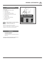
SAFETY INFORMATION
General Safety Instructions .......................................5
General recommendations ........................................5
Hitching the machine to the tractor ...........................5
Machine operation .....................................................6
Road circulation .........................................................8
Handling bales ...........................................................8
Cardan shaft and PTO ...............................................9
Hydraulic system .....................................................10
Servicing the machine .............................................11
Adhesive safety plates .............................................11
Safety plates - location ............................................12
Noise level ...............................................................14
Product clogging removal........................................14
GENERAL INFORMATION
Purpose of the manual ............................................15
Attachments ............................................................15
Warranty ..................................................................15
Machine identification..............................................16
Enclosures ...............................................................16
TECHNICAL INFORMATION
Prescribed use and machine description ................17
Improper use ...........................................................17
Description of the main units ...................................18
Operation description ..............................................19
Technical characteristics .........................................20
Tractor requirements ................................................21
Admissible gradients ...............................................22
Safety devices .........................................................23
Area of danger .........................................................25
Night work ...............................................................25
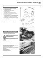
INSTALLATION INSTRUCTIONS
Packing/ Unpacking ................................................26
Lifting .......................................................................26
Load/ Unload from transportation means ...............27
Hitching to the tractor ..............................................27
Coupling to the towing eye ......................................27
Cardan shaft - Installation .......................................28
Hydraulic system - Connection ...............................28
Electric connection of the automatic binder ............29
Binding Control Unit - Installation ...........................29
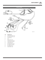
Electric connection of the lighting system ...............30
Releasing from the tractor .......................................30
Opening guards .......................................................31
Tests and checks .....................................................31
OPERATION ADJUSTMENTS -
ADJUSTMENTS AND INDICATORS
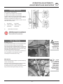
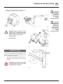
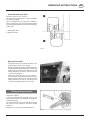
Bale weight choosing ..............................................32
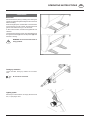
Pick-up - Balancing .................................................32
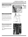
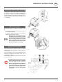
Pick-up height - Adjustment ....................................33
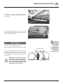
Baffle plate - Adjustment .........................................33
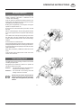
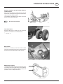
Drive change (Mod. 3500) .......................................33
Feed chain - Adjustment .........................................34
Adjustment of hook closure .....................................34
Adjustment of the hook springs ..............................34
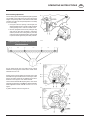
Binder control - Adjustments ...................................35
Slide holding chain path and stroke ........................35
Twine shuttle nose adjustment ................................35
OPERATING INSTRUCTIONS
Binding control unit - Instructions for use ...............36
Twine binding instructions .......................................38
Binder start position ................................................38
Twine installation and connection............................38
Twine splicing ..........................................................39
Clamp adjustment ...................................................39
Binding selection .....................................................39
Twine binder operation ............................................41
What to do in case of damage ................................42
Net wrapping instructions .......................................43
Net assembly and connection .................................43
Binder start position ................................................44
Selecting the number of bale wrappings .................45
Reel braking device .................................................45
Roller pressure adjustment ......................................45
Net binder operation ................................................46
Knife resetting tie rod ..............................................46
Adjusting end of stroke blocks and shock
absorbers .................................................................47
Mixed net/ twine binding instructions .....................48
Automatic running ...................................................48
Manual running ........................................................49
What to do in case of failur ......................................49
Product preparation .................................................49
Forward speed diagram ..........................................50
Picking up instructions ............................................51
Floating straw presser plate ....................................52
Bale unloading .........................................................53
Attachments ............................................................54
MAINTENANCE
General maintenance instructions ...........................57
Routine maintenance ...............................................58
Gear box - Lubrication.............................................59
Cardan shaft - Lubrication .......................................59
Drive chains - Adjustment .......................................59
Twine binder - Servicing ..........................................60
Net binder - Servicing ..............................................60
Centralised automatic lubrication ............................60
Lubrication chart ......................................................61
Table of lubricants ...................................................62
End of season checking in a work shop ..................62
TROUBLESHOOTING
Troubles: causes and remedies ...............................64
General troubles ......................................................64
Bale quality ..............................................................65
2-Twine binder .........................................................65
Net binder (Rotomec) ..............................................66
Clarification of “Section” table ................................66
REPAIR AND REPLACEMENTS OF PARTS
Tools ........................................................................67
Pick-up - Safety bolt replacement ...........................67
Ring gear release .....................................................68
Wheel wedges .........................................................69
Replace the feed chain bearings .............................69
SUPPLEMENT
Hydraulic diagram ..................................................70
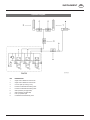
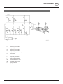
Electric system ........................................................71
Electric system .......................................................72
Binding modes ........................................................73
Electrical lay-out .....................................................74
Electrical lay-out of Main cabling ............................76
Electrical lay-out of twine binding device cabling ...78
SUPPLEMENT
Recommendations for work safety .........................81
Driveshaft .................................................................82
Lubricants ................................................................ 84
Combination of tractor and mounted implement ....86

- 5 -
0500-GB SICHERHEIT_8411
GB
SAFETY INFORMATION
General Safety Instructions
It is of the utmost importance to comply with work safety
regulations issued by the competent authorities of each
country. The following precautions concerning the machine
operation must be duly observed.
General recommendations
Read carefully this manual before starting,
operating and servicing the machine.
• Read carefully safety decals stuck to the machine and
follow the instructions (see paragraph "ADHESIVE
SAFETY PLATES"). Should decals be damaged or
illegible, immediately replace them, applying to SPARE
PARTS DEPARTMENT.
• Before running the machine, the operator must be
informed about and trained to the machine use.
• Do not operate the machine if wearing clothes which
might entangle into running parts.
• Start working only if the machine is in perfect
conditions.
• Check the conditions of the various components
of the pick-up to ensure proper feed and prevent
jammings.
• Do not use the machine to pick up unsuitable products
and in case of bad weather conditions.
• To prevent rotation, the cardan shaft guard must always
be in perfect working order and fastened through the
relevant chains. Read carefully all instructions provided
by the manufacturer.
• Guards must always be in perfect working order.
• Before resuming work, make sure that all guards have
been properly fitted.
• Always keep a first aid kit within reach.
• A fire extinguisher should also be kept within reach.
Hitching the machine to the tractor
• Before hitching the machine to the tractor, make sure
that the latter is in good working order and that brakes
work correctly, particularly if the machine is to be used
on gradients.
• Furthermore, make sure that the hydraulic system of
the tractor suits the machine system.
• To avoid accidents or damages to the machine, make
sure that the cardan shaft is properly connected both
to the machine and to the tractor.
• Make sure that the tractor drawbar coupling pin is
locked, to prevent it from releasing.
• Make sure that the electric system and turn indicators
work properly.

- 6 -
0500-GB SICHERHEIT_8411
SAFETY INFORMATION GB
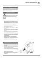
Machine operation
• Before starting the machine, make sure that all safety
guards are in perfect working order and correctly
fitted.
• Only the driver must operate the tractor; no passengers
are allowed on the baler.
• The baler can be operated from the driver’s seat
only.
• Do not walk or stand on the baler drawbar or on other
parts while it is running or when the PTO is engaged.
• Keep far from the pick-up area, belts and rollers of the
machine as well as from binding and running parts.
• People are not allowed to approach the machine during
running and in particular they must not stand in the rear
part of the machine during bale unloading phases.
• Do not stand between the tractor wheels and the
machine when the engine is on.
• Always remove the tractor ignition key and engage the
handbrake when the tractor is unattended.
• Before cleaning, greasing or adjusting the machine or
the PTO, stop the latter, stop the engine, remove the
ignition key and engage the parking brake.
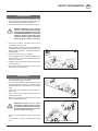
In case of clogging, do not release the baler
while running and unload the bale.
Stop the PTO and the tractor engine before
cleaning the pick-up.
Do not remove from or introduce products
into the pick-up with hands or feet while
the baler is running.
Unload the bale.

- 7 -
0500-GB SICHERHEIT_8411
SAFETY INFORMATION GB
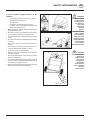
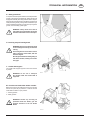
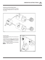
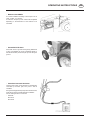
In case of product clogging removal, do the
following:
- do not approach the pick-up when it is running;
- disengage the power take-off;
- stop the tractor;
- use a tool to remove the product clogged;
- if need be, open the tail gate and unload the bale
before cleaning the pick-up.
• Before opening the tail gate, make sure that the area
behind the baler is clear.
• Should the machine be operated with the tail gate
open, fit safety catches on both hydraulic jacks.
• Do not leave the baler unattended when the tail gate
is open.
• Do not leave the machine unattended when the tractor
is running.
• Never open gates or guards while the tractor is
running.
• Do not stand on the upper guard of the pick-up or on
running boards while the machine is running.
• Do not use controls or hoses as grips.
• Beware of curves and overturning on bumping soils
and steep gradients.
• Give the greatest attention when wheels are nearby
ditches or steep banks.
• To avoid exposure to dust and soil caused by picked-up
products, always wear glasses and mask when working
with tractors not supplied with cab.
• Always keep the machine in perfect working order and
perform routine maintenance periodically.
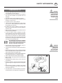
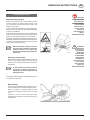
WARNING:
whoever stands
in the machine
working range is
in a dangerous
area, being
therefore an
„exposed
person“.
The operator must
prevent people
from standing in
dangerous areas
and must give the
greatest attention
when operating
the machine.
WARNING:
make sure that
there are no
children; make
sure they do
not approach
the machine
and the tractor.
Give a particular
attention
during reverse

- 8 -
0500-GB SICHERHEIT_8411
SAFETY INFORMATION GB
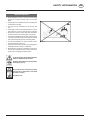
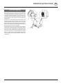
Road circulation
• During road transport, follow the regulations in force
and drive tractors with adequate towable weight only
(see the registration certificate of the tractor).
• Do not use the machine as a transportation means.
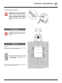
DANGER - WARNING: a wrong assembly
of tyres on rims and an inflation pressure
differing from the values shown by the table
"TRACTOR REQUIREMENTS", might cause
dangerous accidents, particularly during
road transportation. Apply to specialised
workshop, should a check be necessary.
• During road circulation, the cardan shaft must be
connected to the tractor PTO.
• Before towing the machine on the road, raise the pick-up
completely and close the valve on the hydraulic hose
(see paragraph installation "HYDRAULIC SYSTEM-
CONNECTION").
• Hook the pick-up to the chain supplied.
• Do not exceed the maximum speed permitted by the
highway code and, in any case, never exceed the speed
of 40 km/h or 25 mph.
• Periodically check the working order of the lighting and
signalling systems.
• The operator must always be aware of the machine
dimensions during manoeuvres.
Handling bales
• Give the greatest attention to the weight and barycenter
of the lifted bale if using front loaders.
• For covering short distances, bales can be transported
by equipping the tractor with front or rear fork, whereas
for greater distances normal or special trucks must be
used.
Keep to the current legislation during transport on
public roads.
• Never unload or store bales along gradients, since
bales might roll down.
• Make sure that bales are correctly fastened through
ropes or other suitable means.
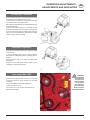
DANGER OF FIRE: straw is highly
inflammable, it might cause fire. In case of
fire, immediately unload the bale and move
the machine away. If necessary, disconnect
the machine from the tractor.
• Fire risks can be avoided by keeping the machine
clean.
• It is advisable to keep a fire extinguisher within
reach.

- 9 -
0500-GB SICHERHEIT_8411
SAFETY INFORMATION GB
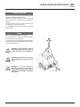
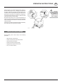
Cardan shaft and PTO
• The power take off of the tractor must turn at the speed
recommended by the manufacturer.
• The cardan shaft must be manufactured in compliance
with EN1152 standards and provided with CE
certificate.
• The cardan shaft must be supplied with guards.
• Make sure not to damage the cardan shaft guard during
transport or working cycle.
• All guards must be in good conditions.
• * Before cardan shaft is installed onto or taken off the
p.t.o., the p.t.o. must be switched off, the motor turned
off and ignition key removed
• The safety joint must be installed on the side of the
baler. The homocinetic joint joint must be installed on
the tractor side.
• Make sure that all rotating parts connected to the PTO
shaft are properly protected.
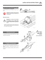
• In order to prevent crawling, assemble the cardan
shaft supplied with the machine between the tractor
PTO and the machine gear box, making sure that the
length does not exceed the min. distance between
the machine and the tractor. Should the cardan shaft
be shortened, cut both pipes and the relevant guards,
removing burs and greasing ends.
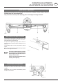
The shaft length must ensure a sufficient
overlap of the telescopic shafts; the tractor
must be perfectly aligned with the machine
and keep a minimum overlap of half.
• Ensure that all turning parts connected to the p.t.o.
cardan shaft are properly safeguarded
• Connect chains to prevent any protection devices from
rotating
• Before engaging the PTO, make sure that the selected
tractor PTO speed and the rotation direction match
with the baler rotation and speed values.
• Before engaging the PTO, make sure that nobody stands
in the baler working area or in dangerous areas.
• Never engage the PTO with the engine stopped.
• Make sure that nobody approaches the cardan shaft
during running.
• Disengage the PTO before sharp curves or when it is
not necessary.
• Before any operation, make sure that the machine and
the tractor engine are stopped and remove the ignition
key.
• Before cleaning, greasing or adjusting the machine
or the PTO, disengage the latter, stop the engine and
remove the ignition key.
• The cardan shaft, once disconnected from the tractor,
must be placed on the support at the drawbar end.
WARNING
• Keep to the
instructions of
the cardan shaft
operation manual.
WARNING:
should running
parts rotate after
the PTO has been
disengaged, keep
far from rotating
parts.

- 10 -
0500-GB SICHERHEIT_8411
SAFETY INFORMATION GB
Hydraulic system
• Before connecting or disconnecting the hydraulic
system pipes of the tractor, release pressure from the
tractor and machine systems.
• Give the greatest attention to hydraulic coupling
between the tractor and the machine: it is advisable to
mark male and female couplings to avoid manoeuvre
errors. Should hydraulic couplings be changed,
some functions might accordingly be changed (ex.
lift/lowering).
Danger of accidents!
• Periodically check hydraulic pipes and replace them
when damaged or worn-out. Replacing pipes must
have the same technical specifications as the original
pipes. Hoses must however be replaced after 5 years
from the date printed on the hose.
• When detecting leaks, use suitable protections.
Danger of accidents!
• The hydraulic pressurised oil might penetrate the skin,
thus causing serious damages. In such a case, consult
a doctor immediately.
Danger of serious infections!
• Before servicing the hydraulic system, lower the baler
tail gate, the pick up, release pressure and stop the
tractor engine.
• To prevent hydraulic couplings from getting dirty or
damaged, always fit the protection caps supplied after
use.
WARNING:
the hydraulic
system works
at high pressure
(min 100 bar /
max 190 bar).
CAUTION:
do not dispose of
hydraulic oil in the
environment.

- 11 -
0500-GB SICHERHEIT_8411
SAFETY INFORMATION GB
Servicing the machine
• Replace as soon as possible all worn or damaged parts
of the pick-up to prevent frequent jammings.
• Comply with scheduled maintenance intervals. From
time to time the machine requires minor servicing.
It should be reminded that a correct and regular
maintenance will increase the working life of the
machine.
• Always replace the belts when these are worn or
damaged.
• Before carrying out any operation over or under the
machine, make sure to insert wedges under wheels.
• When servicing the hydraulic system, make sure that
the system is not pressurised before disconnecting
any pipe.
• Leaks of pressurised oil might cause serious injuries.
When searching for oil leaks always wear protective
clothes, goggles and gloves.
• Before welding machine parts or before servicing the
electric system, release the baler from the tractor, to
protect the alternator and the battery of the latter.
• To avoid fire risks, always keep the machine clean.
• Belts and rollers must be cleaned at least once a day
or whenever used.
• Tyres must be serviced by skilled personnel and through
appropriate tools. A wrong assembly might cause
serious injuries or death. In case of doubts, apply to
qualified personnel.
• To avoid damages to mechanical parts, do not use
pressurised water jets to clean the machine.
Adhesive safety plates
It is of the utmost importance to give the greatest attention
to adhesive warning and/or precautions plates fitted on
the machine, when starting, repairing or simply standing
nearby it.
The user shall keep all plates legible, changing their location
should they fail to be seen and replacing them when
damaged. Damaged plates must be replaced by ordering
a complete set to SPARE PARTS DEPARTMENT.

- 12 -
0500-GB SICHERHEIT_8411
SAFETY INFORMATION GB
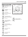
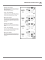
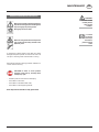
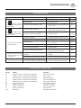
Safety plates - location
1 - General danger!
Read the manual before operating the
machine.
(Code 8889379)
2 - No standing!
Do not stand within the working range
of the machine.
(Code 8889286)
3 - General danger!
Stop the tractor and remove the ignition
key before servicing the machine.
(Code 8889378)
4 - Danger of body crushing!
Fasten the lifting jack through the locking
device before accessing the dangerous
area.
(Code 8889380)
5 - Danger of chest crushing!
Keep far from the baler tail gate while the
tractor engine is running.
(Code 8889381)
6 - Danger of arm entangling!
Do not approach the pick up area with
hands or feet while the tractor engine
is running.
(Code 8889390)
7 - Danger of chest crushing!
Bale out of control.
(Code 8889383)
8 - Danger of chest crushing!
Tail gate is closing.
(Code 8889382)
9 - Danger of arm entangling!
Do not open and remove safety guards
while the engine is running.

- 13 -
0500-GB SICHERHEIT_8411
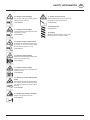
SAFETY INFORMATION GB
10 - Danger of arm entangling!
Do not open and remove safety guards
while the engine is running.
(Code 8889384)
11 - Danger of arm entangling!
Do not introduce hands into the auger while
the engine is running.
(Code 8889389)
12 - Danger of finger or hand cutting!
Do not approach the knife cutting area with
hands. Do not open and remove safety
guards while the engine is running.
(Code 8889377)
13 - Danger of chest crushing!
Keep far from the baler drawbar range while
the tractor engine is running.
(Code 8889394)
14 - Danger of chest crushing!
Keep far from the tractor range while the
engine is running.
(Code 8889393)
15 - Danger of contact with hydraulic
fluids!
Pressurised fluid leaks might penetrate the
skin causing serious injuries.Disconnect
the machine and stop the tractor before
servicing.
(Code 8889969)
16 - Danger of leg cutting or crushing!
Keep far from the machine range.
(Code 8889970)
17 - Danger of electric shock!
Give the greatest attention when operating
the machine nearby electric cables.
(Code 8889968)
18 - Safety devices!
(Code 8889726)
19 - Danger!
Wheels in transport position - before using
the machine turn around the wheels!

- 14 -
0500-GB SICHERHEIT_8411
SAFETY INFORMATION GB
Noise level
According to 86/188 EEC standards and to the current
national law, the following noise levels, detected during
work and measured in dBa, in accordance with ISO 5131
regulation should not be exceeded.
Noise level is measured with the engine and all systems
working, at a normal running speed, according to the
specific use, without product fed into the machine.
To measure the noise level of the tractor-machine unit, the
noise of the baler trailed by the tractor is measured at a
distance of 200 m from the rear window of a cabsupplied
tractor, suitable for trailing the baler.
As far as cab-supplied tractors are concerned, the noise
heard by the operator, keeping doors and windows closed,
will be less, depending on the cab acoustic insulation.
If the tractor is not supplied with cab or works with open
doors and windows, the noise level will exceed 85(dBa),
therefore it is advisable to wear protective headphones.
Since said regulation is in force in many countries, the
operator shall comply with the local current law.
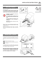
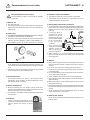
Product clogging removal
DANGER - WARNING: In case of product
clogging removal, do the following:
- do not approach the pick-up when it is running;
- disengage the power take-off;
- stop the tractor;
- use a tool to remove the product clogged; if need be,
open the tail gate and unload the bale before cleaning
the pick-up.
CAUTION: Before starting work always
check the conditions of the components
of the pick up (tines, bars, bushes, cam,
clamps).

GB
GENERAL INFORMATION
- 15 -
0200-GB ALLGEMEINE INFO (8412)
Read this manual carefully before servicing
the machine. This manual must be perfectly
kept inside the plastic bag and put inside
the twine case.
Purpose of the manual
This manual has been drafted by the manufacturer and is
integral part of the machine (1).
Information contained herein is aimed at qualified and
skilled personnel (2) (operators).
Dealers of new or second-hand machines must provide
this manual, previously supplied with the machine.Should
the machine be sold, the purchaser must be supplied with
the operation and maintenance manual.
Should this manual be damaged or lost, order another
to SPARE PARTS DEPARTMENT, specifying its number,
or if missing, all data printed on the rating plate fitted to
the machine.
The manual defines the purpose for which the machine has
been manufactured as well as all information necessary
to ensure a safe and correct operation.
The compliance with the instructions contained herein
ensures both the operator’s and machine safety, running
economy and prolong the working life of the machine.
Particularly important paragraphs have been highlighted
in bold characters and preceded by the following
symbols.
WARNING: shows imwhich might cause
injuries, give it the greatest attention.
CAUTION: shows that it is necessary to
give particular attention to avoid accidents
or damages to things.
Shows particularly important technical
Pictures and figures are merely supplied as examples.
Should the machine owned differ from figures shown in
this manual, safety information is however ensured.
Some figures show the machine with open or removed
guards, to make features and adjustments clearer.
Never operate the machine under these
conditions.
For safety purposes, make sure that all safety guards are
closed or correctly fitted before starting the machine.
In pursuing a policy of constant development and updating
of the product, the manufacturer might introduce changes
or improvements to the machine whenever he deems it
possible, without introducing said changes to the machines
previously sold.
(1) The machine definition replaces the trade definition, object of this
manual (see the cover).
(2) Operators who have acquired a specific experience, technical skill and
knowledge of the current law, who are able to operate the machine and
avoid any danger when handling, installing, operating and servicing
the machine.
Attachments
The machine has been designed to work under different
conditions and products. However, additional attachments
might be required to improve the performance.
A list of optional attachments is shown in the chapter
”Attachments” of this manual.
Warranty
The machine is in compliance with the law in force in the
user’s country and the conditions agreed with the dealer.
The warranty shall be void should the machine be damaged
or changed, disregarding the instructions set forth in the
operation manual.

- 16 -
0500-GB ALLGEMEINE INFO_8411
GENERAL INFORMATION GB
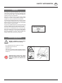
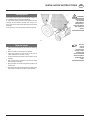
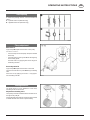
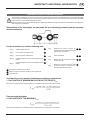
Machine identification
The model is identified by the rating plate showing the
following data:
A - Commercial name of the machine
B - Serial number
C - Year of construction
D - Type of approval (in force in Italy)
E - Number of road approval (in force in Italy)
F - Max. PTO rpm
G - Total max. mass
H - Total max. mass on towing eye
L - Max. mass on axle
M - Manufacturer
Always indicate A - B - C when requesting
information, spare parts, etc.
Always use original spare parts if necessary.
Using non original spares or performing unauthorised
operations on the machine will void the warranty.
Enclosures
- EC Conformity Declaration
- Type approval certificate.
- Conformity declaration for type-approved vehicles
(Italy only).
These documents are to be kept safe and protected from
the weather for the entire life of the machine.

- 17 -
0200-GB TECHNISCHE INFO_8411
GB
TECHNICAL INFORMATION
Prescribed use and machine description
This machine is a pick-up baler, designed exclusively to
collect windrows of straw, hay and similar products, and
press such products into cylindrical bales.
This is a trailed machine and requires a suitable tractor unit
for pulling and powering the transmission drive.
The machine picks up and bales fodder, including mixed
gramineae and lucerne, for agricultural use on lands
under crop.
All picking up, binding and unloading operations are
controlled by the operator from the tractor cab.
This machine can be used to harvest different crops:
graminaceous crops, straw, hay, maize stalks, ensiled
produce, thanks to its combination of rollers and
chains.
The machine can be equipped with a wide pick-up, with
large-diameter side augers, for wide and bulky windrow
harvesting. The bale can be twine bound, net wrapped
or mixed bound.
As soon as binding is over, the bale is unloaded by opening
the tail gate.
The machine has been manufacturer to be used by a single
operator (tractor driver).
Comply with the accident prevention regulations in force
in the user’s country.
Use original spare parts only.
Improper use
• The machine cannot be used as a transport means for
people or things.
• Do not allow people to remain on the service running
board while the machine is running.
Always stop the power take off.
• Do not change, remove or assemble parts to the
machine. The manufacturer shall not be liable for
damages thus caused.
• Do not exceed the speed of 40 Km/h.
• The manufacturer shall not be liable for damages caused
by non-original spare parts and attachments.

- 18 -
0200-GB TECHNISCHE INFO_8411
TECHNICAL INFORMATION GB
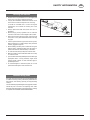
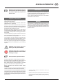
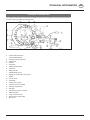
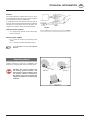
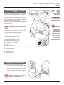
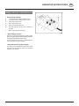
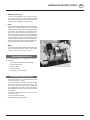
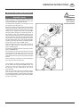
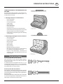
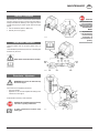
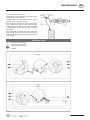
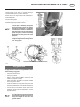
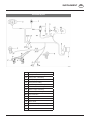
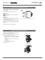
Description of the main units
The ”Pöttinger” 3000 series is a versatile line: any standard machine can be completed by requesting optional assemblies
in order to meet any possible user’s requirements.
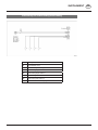
A - Cardan shaft transmission
(see enclosed literature).
B - Drawbar for coupling to tractor
C - Parking jack.
D - Gearbox.
E - Chain drive.
F - Feeding/pressure rollers.
G - Feed chain.
H - Baling chamber.
I - Standard/wide pick-up.
K - Bearing for Cardan shaft in rest position.
L - Wheels.
M - Pick-up wheel.
N - Feed baffle.
P - Floating straw-presser.
Q - Two-twine tying unit (Autolife).
R - Net tying unit (Rotomec).
S - Rear gate.
T - Gate opening hydraulic cylinders.
U - Bale kicker (OPT).
V - Tying unit remote control.
Y - Electric lighting system (OPT).
Z - Main pinion

- 19 -
0200-GB TECHNISCHE INFO_8411
TECHNICAL INFORMATION GB
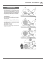
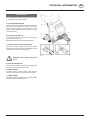
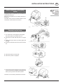
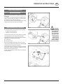
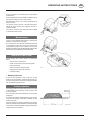
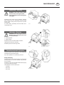
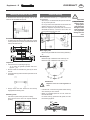
Operation description
- All machine functions are directly controlled and
supervised from the tractor driver’s cab.
- The machine will move on along the windrow to allow
the crop to be harvested by the pick-up; the crop is
then fed to the baling chamber by the feeding rollers.
- The baffle will help product feeding to the chamber.
- The product is pressed into round bales inside the
chamber; when the required bale pressure is reached,
a sound signal will inform the operator that the tractor
should be stopped.
- The twine or net tying unit will begin automatic or
manual bale tying.
- A sound signal is operated when tying is completed.
- If the machine is not equipped with bale kickers, about
2 - 3 meters in reverse are necessary before the gate
can be opened.
- The operator should now opening the gate to allow
bale unloading on the ground.
- Move ahead of 2 to 3 metres.
- The gate is then fully closed again and the machine is
ready for another cycle.

- 20 -
0200-GB TECHNISCHE INFO_8411
TECHNICAL INFORMATION GB
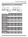
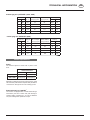
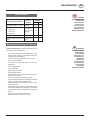
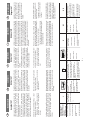
Technical characteristics
3120 - 3200 3120L - 3200L 3150 - 3500 3150L - 3500L
Feeding
Chamber section mm ø 1200x1200 ø1200x1200 ø1500x1200 ø1500x1200
Pick-up
Pick-up width mm 1200 1680 1200 1680
Tines for row/ tines rows n 20/4 28/4 20/4 28/4
Distance between tines mm 60 60 60 60
Weights
Machine weight kg 2200 2320 2430 2550
Bale
Haybale weight kg 250/320 250/320 390/500 390/500
Straw bale weight kg 170/220 170/220 260/340 260/340
Silage bale weight kg 400/700 400/700 620/1000 620/1000
Bales hourly output n 15/30 18/35 15/30 18/35
Tyres
Tyre 10.0/75-15 10.0/75-15 10.0/75-15 10.0/75-15
Tyre pressure bar 3,7 3,7 3,7 3,7
Wheel for pick-up 16x6.50-8 6PR 16x6.50-8 6PR 16x6.50-8 6PR 16x6.50-8 6PR
Wheel pressure bar 2,5 2,5 2,5 2,5
Twine/Netting
Twine m/kg 500/800 500/800 500/800 500/800
strong mesh net gr/m 14/18 14/18 14/18 14/18
La pagina si sta caricando...
La pagina si sta caricando...
La pagina si sta caricando...
La pagina si sta caricando...
La pagina si sta caricando...
La pagina si sta caricando...
La pagina si sta caricando...
La pagina si sta caricando...
La pagina si sta caricando...
La pagina si sta caricando...
La pagina si sta caricando...
La pagina si sta caricando...
La pagina si sta caricando...
La pagina si sta caricando...
La pagina si sta caricando...
La pagina si sta caricando...
La pagina si sta caricando...
La pagina si sta caricando...
La pagina si sta caricando...
La pagina si sta caricando...
La pagina si sta caricando...
La pagina si sta caricando...
La pagina si sta caricando...
La pagina si sta caricando...
La pagina si sta caricando...
La pagina si sta caricando...
La pagina si sta caricando...
La pagina si sta caricando...
La pagina si sta caricando...
La pagina si sta caricando...
La pagina si sta caricando...
La pagina si sta caricando...
La pagina si sta caricando...
La pagina si sta caricando...
La pagina si sta caricando...
La pagina si sta caricando...
La pagina si sta caricando...
La pagina si sta caricando...
La pagina si sta caricando...
La pagina si sta caricando...
La pagina si sta caricando...
La pagina si sta caricando...
La pagina si sta caricando...
La pagina si sta caricando...
La pagina si sta caricando...
La pagina si sta caricando...
La pagina si sta caricando...
La pagina si sta caricando...
La pagina si sta caricando...
La pagina si sta caricando...
La pagina si sta caricando...
La pagina si sta caricando...
La pagina si sta caricando...
La pagina si sta caricando...
La pagina si sta caricando...
La pagina si sta caricando...
La pagina si sta caricando...
La pagina si sta caricando...
La pagina si sta caricando...
La pagina si sta caricando...
La pagina si sta caricando...
La pagina si sta caricando...
La pagina si sta caricando...
La pagina si sta caricando...
La pagina si sta caricando...
La pagina si sta caricando...
La pagina si sta caricando...
La pagina si sta caricando...
La pagina si sta caricando...
La pagina si sta caricando...
-
 1
1
-
 2
2
-
 3
3
-
 4
4
-
 5
5
-
 6
6
-
 7
7
-
 8
8
-
 9
9
-
 10
10
-
 11
11
-
 12
12
-
 13
13
-
 14
14
-
 15
15
-
 16
16
-
 17
17
-
 18
18
-
 19
19
-
 20
20
-
 21
21
-
 22
22
-
 23
23
-
 24
24
-
 25
25
-
 26
26
-
 27
27
-
 28
28
-
 29
29
-
 30
30
-
 31
31
-
 32
32
-
 33
33
-
 34
34
-
 35
35
-
 36
36
-
 37
37
-
 38
38
-
 39
39
-
 40
40
-
 41
41
-
 42
42
-
 43
43
-
 44
44
-
 45
45
-
 46
46
-
 47
47
-
 48
48
-
 49
49
-
 50
50
-
 51
51
-
 52
52
-
 53
53
-
 54
54
-
 55
55
-
 56
56
-
 57
57
-
 58
58
-
 59
59
-
 60
60
-
 61
61
-
 62
62
-
 63
63
-
 64
64
-
 65
65
-
 66
66
-
 67
67
-
 68
68
-
 69
69
-
 70
70
-
 71
71
-
 72
72
-
 73
73
-
 74
74
-
 75
75
-
 76
76
-
 77
77
-
 78
78
-
 79
79
-
 80
80
-
 81
81
-
 82
82
-
 83
83
-
 84
84
-
 85
85
-
 86
86
-
 87
87
-
 88
88
-
 89
89
-
 90
90


Pottinger ROLLPROFI 3120 Istruzioni per l'uso
- Tipo
- Istruzioni per l'uso
- Questo manuale è adatto anche per
in altre lingue
Documenti correlati
-
Pottinger ROLLPROFI 3200 L Istruzioni per l'uso
-
-
-
-
-
-
-
-
-

