Hatco GLO-RAY GR-24 Installation & Operating Manual
- Tipo
- Installation & Operating Manual

FOOD WARMER
Glo-Ray
®
Standard and Portable
Installation &
Operating Manual
I&W #07.05.042.00
SPEISEWÄRMER
Installations- und Bedienungshandbuch
Modelle: GLO-RAY
®
Standard- und Tragbare Ausführung
RAMPES CHAUFFANTES
Installation et Fonctionnement
Modèle: GLO-RAY
®
Courant et portatif
VOEDSELVERWARMER
Handleiding voor Installatie en Bediening
Model: GLO-RAY
®
Standaard en Draagbare Versieh
CALENTADORES DE COMIDAS
Manual de Instalación y Operación
Modelo: Glo-Ray
®
Estándar y portátil
RISCALDATORI
Manual de Instalación y Operación
Modelo: Riscaldatori di Cibo Glo-Ray
®
Standard e Portatile


Glo-Ray
®
Food Warmer
1
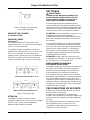
GENERAL
Safety precautions preceded in this manual by the
words WARNING or CAUTION printed in bold face
are important. WARNING means there is the possibil-
ity of personal injury to yourself or others. CAUTION
means there is the possibility of damage to the unit.
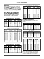
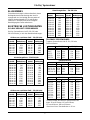
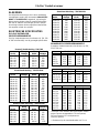
ELECTRICAL SPECIFICATIONS
GLO-RAY INFRARED FOODWARMERS
Glo-Ray Food Warmers operate on 120, 220 or
240 volts depending on order specifications.
PORTABLE FOODWARMERS
Portable Foodwarmers operate on 120, 220 or
240 volts.
* Indicates models that accommodate multiple food
pans: 30" (76 cm)=2 pans, 42" (107 cm)=3 pans,
54" (137 cm)=4 pans and 66" (168 cm)=5 pans.
** Based on standard width of 19-1/2" (50 cm).
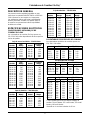
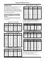
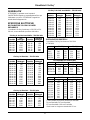
Stainless Steel Housing – 220-230 Volts
High Standard
Model Wattage Model Wattage
GRH-24 546 GR-24 383
GRH-36 874 GR-36 628
GRH-48 1202 GR-48 874
GRH-60 1530 GR-60 1148
GRH-72 1913 GR-72 1394
GRH-96 2623 GR-96 1885
220-230V 230-240V
Model Watt Amps Watt Amps
GR-B 273 1.30 250 1.04
GRFF 546 2.59 500 2.08
GRFFL 678 3.22 620 2.58
GRFFB 820 3.90 750 3.13
GRFFBL 951 4.52 870 3.63
FRY STATIONS
220-230V 230-240V
Model Watt Amps Watt Amps
GRFS-24 546 2.59 500 2.08
GRFSL-24 678 3.22 620 2.58
GRFSR-24 546 2.59 500 2.08
GRFSLR-24 131 0.62 120 5.00
HEATED SHELVES
220-230V 230-240V
Model Watt** Amps Watt** Amps
GRS-18 262 1.25 240 1.00
GRS-24 328 1.56 300 1.25
GRS-30* 404 1.92 370 1.54
GRS-36 481 2.29 440 1.83
GRS-42* 546 2.59 500 2.08
GRS-48 612 2.91 560 2.33
GRS-54* 700 3.33 640 2.67
GRS-60 765 3.64 700 2.92
GRS-66* 842 4.00 770 3.21
GRS-72 918 4.36 840 3.50
Stainless Steel Housing – 230-240 Volts
High Standard
Model Wattage Model Wattage
GRH-24 500 GR-24 350
GRH-36 874 GR-36 575
GRH-48 1100 GR-48 800
GRH-60 1400 GR-60 1050
GRH-72 1750 GR-72 1275
GRH-96 2400 GR-96 1725
Aluminum Housing – 220-230 Volts
High Standard
Model Wattage Model Wattage
GRAH-18 383 GRA-18 273
GRAH-24 546 GRA-24 383
GRAH-30 721 GRA-30 492
GRAH-36 874 GRA-36 628
GRAH-42 1038 GRA-42 738
GRAH-48 1202 GRA-48 874
GRAH-54 1366 GRA-54 1011
GRAH-60 1530 GRA-60 1148
GRAH-66 1705 GRA-66 1268
GRAH-72 1885 GRA-72 1394
GRAH-84 2241 GRA-84 1639
GRAH-96 2623 GRA-96 1885
Aluminum Housing – 230-240 Volts
High Standard
Model Wattage Model Wattage
GRAH-24 500 GRA-24 350
GRAH-30 660 GRA-30 450
GRAH-36 800 GRA-36 575
GRAH-42 950 GRA-42 675
GRAH-48 1100 GRA-48 800
GRAH-54 1250 GRA-54 925
GRAH-60 1400 GRA-60 1050
GRAH-66 1560 GRA-66 1160
GRAH-72 1725 GRA-72 1275
GRAH-84 2050 GRA-84 1500
GRAH-96 2400 GRA-96 1725

Glo-Ray
®
Food Warmer
2
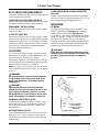
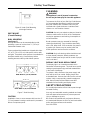
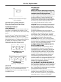
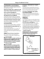
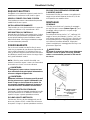
Figure 1. Chain Mounting
ELECTRICAL REQUIREMENTS
For proper installation to local electrical code consult
a licensed electrical contractor.
CORD AND PLUG PROVIDED MODELS
Install an approved grounded receptacle to receive plug
of models provided with supply cord and plug set.
PERMANENT INSTALLATIONS
Install a supply wire not lighter than 10-gauge copper,
rated 90°C (194°F).
CONTROL SWITCHES
When two or more Glo-Ray units are mounted in a situa-
tion where the heat from one housing tends to raise the
temperature of another, the control switches should be
installed in a suitable control box away from the heated
zone. Glo-Ray units ordered for multiple installation
should not have switches built-in.
LOCATION
It is necessary for safe and proper operation that the
food warmer be mounted a reasonable distance from
combustible wall and counter top surfaces.
When proper distances are maintained, hot foods will
be held at ideal serving temperatures without cooking
the foods beyond the point of excellence.
NOTE: Glo-Ray is not moisture-proof. Do not mount
over steamtable unless control switch is in a remote
location.
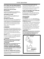
WARNING
Electrical grounding is required on this appliance.
The grounding must come from the main power
supply source and then connected throughout
the appliance.
WARNING
Specified safe distances must be maintained
between the Glo-Ray and combustible wall or wall
type surfaces and wooden counters or counters
that would discolor. If safe distances are not main-
tained, discoloration or combustion could occur.
STANDARD WATTAGE GLO-RAY
Locate standard wattage Glo-Rays so there is a mini-
mum distance of 10" (25 cm) between the bottom of
the Glo-Ray and wooden counters or counters that
would discolor.
HIGH WATTAGE GLO-RAY
Locate high wattage Glo-Ray so there is a minimum
distance of 13.5" (34,3 cm) between the bottom of
the Glo-Ray and wooden counters or counters that
would discolor.
CHAIN SUSPENDED OR WALL MOUNTED
GLO-RAY
Locate a chain suspended, or wall bracket mounted
Glo-Ray so there is a minimum distance of 3" (7,6 cm)
from a nonmetallic wall or adjacent surface.
MOUNTING
GENERAL
Glo-Rays are supplied with 2 mounting tabs at each
end for chain mounting (See Figure 1) or mounting
under a shelf or pass through (See Figure 6).
C-Leg stands, T-Leg stands, wall brackets and tubular
stands are available. C-Leg and T-Leg stands can be
attached to any standard Glo-Ray. A Glo-Ray is
prepared for tubular stand mounting if requested when
ordered. Use only recommended mounting methods
and approved accessories with your Glo-Ray.
WARNING
Chain must be of sufficient strength and securely
fastened or the Glo-Ray Warmer could come loose,
possibly causing personal injury or damage to
the unit.
Overhead chain
Connecting chain
3"
(7,6 cm)
min.
10" (25,4 cm) minimum
Standard Wattage
13.5" (34,3 cm) minimum
High Wattage
Non-metallic wall
Non-metallic surface

Glo-Ray
®
Food Warmer
3
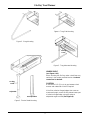
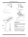
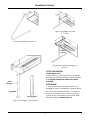
Locking
screw
Adjustable
Non-adjustable
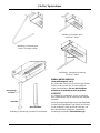
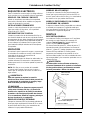
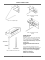
UNDER SHELF
(see Figure 4 & 5)
When mounting the Glo-Ray under a shelf keep any
switches in the coolest possible location. A remote
control box is advised.
CAUTION
A minimum of 1.5" (3,8 cm) air gap between food-
warmer and underside of shelf is required.
If shelf has rolled or flanged edges that create an
overturned trough, mount Glo-Ray below lowest part
of rolled or flanged edge, using the optional
adjustable angle brackets (See Figure 6).
Figure 2. C-Leg Mounting
Figure 4. T-Leg End Mounting
Figure 5. T-Leg Alternate Mounting
Figure 3. Tubular Stand Mounting
Locking
screw

Glo-Ray
®
Food Warmer
4
POST MOUNT
(Consult Factory)
DUAL MOUNTING
(see Figure 7)
Glo-Ray Warmers can be mounted side-by-side,
providing a space of not less than 3" (7,6 cm) is
maintained between units.
Factory ordered dual models are shipped with either
a 3" or 6" (7,6 or 15,2 cm) wide spacer, with or with-
out lights. These dual mount spacers are available for
aluminum models only. Consult factory before
installing warmers side-by-side without spacers.
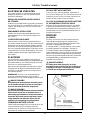
CLEANING
WARNING
The appliance is not of jet-proof construction.
Do not use jet-clean spray to clean this appliance.
To preserve the finish of your Glo-Ray Food Warmer
it is recommended that exterior surfaces be wiped
daily with a damp cloth. Stubborn stains may be
removed with a good aluminum or stainless steel
cleaner or a non-abrasive cleanser.
CAUTION: Use only non-abrasive cleaners. Abrasive
cleaners could scratch the finish of the Foodwarmer
marring its appearance and making it susceptible to
soil accumulation.
Breath protectors may be removed for thorough
cleaning and polishing. They should be wiped daily
with a soft, damp cloth. If fine scratches are present
a good acrylic cleaner may be used to polish the
breath protectors and remove the scratches.
CAUTION: Only soft cleaning cloths should be used
to clean breath protectors. Breath protectors are
made of shatter-proof acrylic and will scratch if proper
care is not taken.
DISPLAY LIGHT BULB REPLACEMENT
The display light is an incandescent bulb which
illuminates the warming area. This bulb has a special
coating to guard against injury and food contamination
in the event of breakage.
To replace a bulb, disconnect the power supply and
wait until the unit has cooled. Display lamps have
a threaded base. Unscrew the bulb from the unit and
replace it with a new specially coated incandescent
bulb. Hatco Shatter-Resistant Bulbs meet NSF
standards for food holding and display areas.
SAFETY PRECAUTIONS
Do not add a decorative soffit to hide a pass-through
mounted Glo-Ray.
Use only recommended mounting methods and mate-
rials and approved accessories to prevent personal
injury or damage to the unit.
Be certain that specified safe and proper distances
are maintained between the Glo-Ray and combustible
wall or wall type surfaces and counters.
See LOCATION.
CAUTION
Installation of two or more warmers with less than 3"
(7.6 cm) between housings could result in premature
failure of component parts.
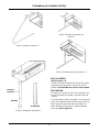
6”
(15,2 cm)
3”
(7,6 cm)
6”
(15,2 cm)
6”
(15,2 cm)
6”
(15,2 cm)
6”
(15,2 cm)
15" (38 cm)
18" (45,7 cm)
Figure 6. Under Shelf Mounting
with Angle Brackets
Figure 7. Dual Mounting
DUAL WITH 3" (7,6 cm) SPACER
DUAL WITH 6" (15,2 cm) SPACER

Glo-Ray
®
Speisewärmer
5
ALLGEMEINES
Sicherheitsvorkehrungen in diesem Handbuch, denen
die fettgedruckten Worte Warnung oder Vorsicht
vorange-stellt sind, sind wichtig. Warnung weist auf
mögliche Verletzungsgefahr für Sie oder andere
Personen hin. Vorsicht macht auf eine mögliche
Beschädigung des Geräts aufmerksam.
ELEKTRISCHE LEISTUNGSDATEN
GLO-RAY INFRAROT SPEISEWÄRMER
Glo-Ray Speisewärmer sind für 120, 220 oder
240 Volt lieferbar, je nach den Bestellanforderungen.
TRAGBARE SPEISEWÄRMER
Tragbare Speisewärmer sind für 120, 220 oder
240 Volt lieferbar.
* Markiert Modelle, die mehreren Speisepfannen Platz
bieten: 76 cm=2 Pfannen, 107 cm=3 Pfannen,
137 cm=4 Pfannen, 168 cm=5 Pfannen.
**Beruht auf einer Standardbreite on 50 cm.
Gehäuse aus rostfreiem Stahl – 220-230 Volts
Hohe Standard
Modell Wattleistung Modell Wattleistung
GRH-24 546 GR-24 383
GRH-36 874 GR-36 628
GRH-48 1202 GR-48 874
GRH-60 1530 GR-60 1148
GRH-72 1913 GR-72 1394
GRH-96 2623 GR-96 1885
220-230V 230-240V
Modell Watt Amps Watt Amps
GR-B 273 1.30 250 1.04
GRFF 546 2.59 500 2.08
GRFFL 678 3.22 620 2.58
GRFFB 820 3.90 750 3.13
GRFFBL 951 4.52 870 3.63
FRITIERSTATION
220-230V 230-240V
Modell Watt Amps Watt Amps
GRFS-24 546 2.59 500 2.08
GRFSL-24 678 3.22 620 2.58
GRFSR-24 546 2.59 500 2.08
GRFSLR-24 131 0.62 120 5.00
BEHEIZTE REGALE
220-230V 230-240V
Modell Watt** Amps Watt** Amps
GRS-18 262 1.25 240 1.00
GRS-24 328 1.56 300 1.25
GRS-30* 404 1.92 370 1.54
GRS-36 481 2.29 440 1.83
GRS-42* 546 2.59 500 2.08
GRS-48 612 2.91 560 2.33
GRS-54* 700 3.33 640 2.67
GRS-60 765 3.64 700 2.92
GRS-66* 842 4.00 770 3.21
GRS-72 918 4.36 840 3.50
Gehäuse aus rostfreiem Stahl – 230-240 Volts
Hohe Standard
Modell Wattleistung Modell Wattleistung
GRH-24 500 GR-24 350
GRH-36 874 GR-36 575
GRH-48 1100 GR-48 800
GRH-60 1400 GR-60 1050
GRH-72 1750 GR-72 1275
GRH-96 2400 GR-96 1725
Aluminiumgehäuse – 220-230 Volts
Hohe Standard
Modell Wattleistung Modell Wattleistung
GRAH-18 383 GRA-18 273
GRAH-24 546 GRA-24 383
GRAH-30 721 GRA-30 492
GRAH-36 874 GRA-36 628
GRAH-42 1038 GRA-42 738
GRAH-48 1202 GRA-48 874
GRAH-54 1366 GRA-54 1011
GRAH-60 1530 GRA-60 1148
GRAH-66 1705 GRA-66 1268
GRAH-72 1885 GRA-72 1394
GRAH-84 2241 GRA-84 1639
GRAH-96 2623 GRA-96 1885
Aluminiumgehäuse – 230-240 Volts
Hohe Standard
Modell Wattleistung Modell Wattleistung
GRAH-24 500 GRA-24 350
GRAH-30 660 GRA-30 450
GRAH-36 800 GRA-36 575
GRAH-42 950 GRA-42 675
GRAH-48 1100 GRA-48 800
GRAH-54 1250 GRA-54 925
GRAH-60 1400 GRA-60 1050
GRAH-66 1560 GRA-66 1160
GRAH-72 1725 GRA-72 1275
GRAH-84 2050 GRA-84 1500
GRAH-96 2400 GRA-96 1725

Glo-Ray
®
Speisewärmer
6
Abbildung 1. Kettenaufhängung
ELEKTRISCHE ANFORDERUNGEN
Zur ordnungsgemäen Installation in Übereinstimmung
mit dem örtlichen elektrischen Kode einen zugelasse-
nen Elektriker zu Rate zu ziehen.
MODELLE MIT ANSCHLUKABEL
UND STECKER
Für den Stecker der Modelle mit Anschlukabel und
Stecker mu eine zugelassene geerdete Steckdose zur
Verfügung stehen oder eingebaut werden.
PERMANENTER EINBAU
Dazu eine Stromleitung aus mindestens Nr. 10
Kupferdraht und mit einem Nennwert von 90°C
(194°F) anbringen.
BEDIENUNGSSCHALTER
Wenn zwei oder mehrere Glo-Rays so aufgestellt sind,
da die Wärme eines Gehäuses die Temperatur eines
anderen erhöhen kann, müssen die Bedienungs-schalter
in einem angemessenen Schaltkasten auerhalb des
erwärmten Bereichs untergebracht werden. Glo-Rays,
die als Teil einer Reihe von Speisewärmern bestellt
werden, sollten keine eingebauten
Schalter haben.
STANDORT
Zum sicheren und ordnungsgemäen Betrieb mu der
Speisewärmer weit genug von brennbaren Wand- und
Arbeitsoberflächen entfernt aufgestellt werden. Wenn
angemessene Abstände eingehalten werden, wird
die ideale Serviertemperatur der heien Speisen
aufrecht erhalten ohne Qualitätsbeeinträchtigungen
durch Überkochen.
HINWEIS: Glo-Ray ist nicht feuchtigkeitsbeständig.
Das Gerät nicht über einer Dampftafel anbringen,
es sei denn der Bedienungsschalter befindet sich
an einem vom Gerät entfernten Ort.
WARNUNG
Dieses Gerät muß geerdet sein. Die Erdung muß
von dem Netzanschluß ausgehen und mit dem
ganzen Gerät verbunden sein.
WARNUNG
Die angegebenen Sicherheitsabstände zwischen
dem Glo-Ray und brennbaren Wand- oder
wandähnlichen Oberflächen und Arbeitsflächen
aus Holz oder verfärbungsanfälligen Arbeitsflä-
chen müssen eingehalten werden. Nichteinhaltung
des Sicherheitsabstandes könnte zu Verfärbungen
und Verbrennung führen.
GLO-RAY MIT STANDARD WATTLEISTUNG
Diese Glo-Rays so aufstellen, da ein Mindestabstand
von 25 cm zwischen dem Boden des Glo-Ray und
Arbeitsflächen aus Holz oder verfärbungsanfälligen
Arbeitsflächen freibleibt.
GLO-RAY MIT HOHER WATTLEISTUNG
Diese Glo-Rays so aufstellen, da ein
Mindestabstand von 34,3 cm zwischen dem Boden
des Glo-Ray und Arbeitsflächen aus Holz oder ver-
färbungsanfälligen Arbeitsflächen freibleibt.
AN KETTEN HÄNGENDE ODER WAND MON-
TIERTE GLO-RAY MODELLE
Bei Glo-Rays, die an Ketten hängen oder mit einem
Befestigungsbügel an der Wand montiert sind, einen
Mindestabstand von 7,6 cm zu nichtmetallischen
Wand- und anderen Oberflächen freilassen.
MONTIERUNG
ALLGEMEINES
Zur Aufhängung an einer Kette (Siehe Abbildung 1)
oder unter einem Regal oder einer Durchreiche (Siehe
Abbildung 6) werden die Glo-Rays mit 2 Aufhängern
an beiden Enden geliefert.
C-förmige Ständer, T-Stützen, Wandbefestigungs-bügel
und Röhrenständer sind erhältlich. C-förmige Ständer
und T-Stützen können an jedem Standard Glo-Ray
Modell angebracht werden. Glo-Rays werden zur
Aufstellung auf Röhrenständern vorbereitet wenn das
bei der Bestellung gewünscht wird. Nur empfohlene
Montierungsmethoden und anerkanntes Zubehör mit
Ihrem Glo-Ray verwenden.
WARNUNG
Die Kette mu stark genug sein und sicher befestigt
sein oder der Glo-Ray Speisewärmer kann sich
lösen und möglicherweise Verletzungen oder
Schäden am Gerät verursachen kann.
Zuleitungskette
Verbindungskette
minderstens
7,6 cm)
minderstens 25,4 cm
Standard Wattleistung
minderstens 34,3 cm
Hohe Wattleistung
Nichtmetallische Wandfläche
Nichtmetallische Oberfkäche

Glo-Ray
®
Speisewärmer
7
Verriegelungs-
schraube
Verstellbar
Nicht Verstellbar
EINBAU UNTER REGALEN
(Siehe Abbildungen 4 und 5)
Bei Einbau des Glo-Rays unter einem Regal, darauf
achten, da die Schalter sich an einer möglichst
kühlen Stelle befinden. Ein vom Gerät entfernt
befindlicher Schalterkasten wird empfohlen.
VORSICHT
Ein Luftspalt von mindestens 3,8 cm mu zwischen
dem Speisewärmer und der Unterseite des Regales
bestehen.
Wenn das Regal abgerundete Kanten oder Bordränder
hat, die einen umgestülpten Trog formen, den Glo-Ray
an der niedrigsten Stelle der Kante anbringen und
dazu die wahlweise erhältlichen, verstellbaren
Winkelbügel verwenden (Siehe Abbildung 6).
Abbildung 2. Montierung mit
einem C-förmigen Ständer
Abbildung 4. Montierung mit
einer End-T-Stütze
Abbildung 5. Alternative Montierung
mit einer T-Stütze
Abbildung 3. Montierung auf einem Röhrenständer
Stützschiene

Glo-Ray
®
Speisewärmer
8
REINIGUNG
WARNUNG
Dieses Gerät kann der Reinigung mit einem Hoch-
druck-Wasserstrahlgerät konstruktionsmäßig nicht
stanhalten. Dieses Gerät nicht mit einem
Hochdruck-Wasserstrahlsprühgerät saubernacgen.
Um den Hochglanz Ihres Glo-Ray Speisewärmers zu
erhalten, empfehlen wir tägliches Abwischen der
Auenflächen mit einem feuchten Tuch. Hartnäckige
Flecken können mit einem guten Reinigungsmittel für
Aluminium oder rostfreien Stahl oder einem nicht
scheuernden Reinigungsmittel entfernt werden.
VORSICHT: Nur nicht scheuernde Reinigungsmittel
verwenden. Scheuernde Reinigungsmittel könnten
den Speisewärmer verkratzen, wodurch sein Aus-
sehen beeinträchtigt wird und sich Schmutz leichter
ansammeln kann.
Die Atemschutzplatten können zum gründlichen
Reinigen und Polieren abgenommen werden. Sie soll-
ten täglich mit einem weichen feuchten Tuch abge
wischt werden. Falls sie leichte Kratzer aufweisen,
kann ein gutes Akrylreini-gungsmittel zum Polieren und
zur Beseitigung der Kratzer verwendet werden.
VORSICHT: Nur weiche Tücher zur Reinigung der
Atemschutzplatten verwenden. Diese Platten sind aus
bruchsicherem Akryl hergestellt und werden verkratzt
wenn sie nicht vorsichtig behandelt werden.
AUSWECHSELN DER GLÜHBIRNE IN DER
AUSSTELLUNGSLAMPE
Die Ausstellungslampe ist eine Glühbirne, die den
Warmhaltebereich erleuchtet. Diese Glühbirne ist
speziell beschichtet zum Schutz gegen Verletzungen
und Verschmutzung der Speisen im Zerbruchsfall.
Um die Glühbirne auszuwechseln, das Anschlukabel
aus der Steckdose ziehen und warten bis das Gerät
abgekühlt ist. Die Ausstellungslampen haben eine
Gewindefassung. Die Glühbirne aus dem Gerät
schrauben und durch eine neue, spezielle beschichtete
Glühbirne ersetzen. Die schlagfesten Glühbirnen von
Hatco entsprechen den NSF Normen für Speiseauf-
bewahrungs- und ausstellungsbereiche.
SICHERHEITSVORKEHRUNGEN
Keine dekorative Verkleidung zur Verdeckung eines in
einer Durchreiche angebrachten Glo-Ray anbringen.
Um Verletzungen oder Schaden am Gerät zu vermei-
den, nur empfohlene Einbaumethoden und -materialien
und anerkanntes Zubehör benutzen.
Darauf achten, da die angegebenen Sicherheits-
abstände zwischen dem Glo-Ray und brennbaren
Wand- oder anderen Oberflächen und Arbeitsflächen
eingehalten werden. Siehe unter STANDORT.
VORSICHT
Einbau von zwei oder mehreren Speisewärmern mit
weniger als 3" (7,6 cm) Abstand zwischen den
Gerätegehäusen könnte zu vorzeitigem Versagen von
Geräteteilen führen.
TANDEMEINBAU MIT 15,2 cm
ABSTANDHALTER
TANDEMEINBAU MIT7,6 cm
ABSTANDHALTER
15,2 cm
7,6 cm 15,2 cm
15,2 cm
15,2 cm
15,2 cm
38 cm
45,7 cm
Abbildung 6. Einbau unter einem Regal
mit Winkelbügeln
Abbildung 7. Tandemeinbau
MONTIERUNG AN EINEM PFOSTEN
(Dazu den Hersteller zu Rate ziehen)
TANDEMMONTIERUNG
(Siehe Abbildung 7)
Glo-Ray Speisewärmer können nebeneinander mon-
tiert werden, vorausgesetzt ein Abstand von nicht
weniger als 7,6 cm wird zwischen den Geräten freige-
lassen.
Von der Fabrik zum Tandemeinbau bestellte Geräte
werden mit entweder 7,6 oder 15,2 cm breiten
Abstandhaltern und mit oder ohne Lampen geliefert.
Diese Abstandhalter zur Tandemmontierung sind nur
für Modelle aus Aluminium erhältlich. Vor dem
Tandemeinbau von Speisewärmern ohne
Abstandhal-ter die Fabrik zu Rate ziehen.

Calentadores de Comidas Glo-Ray
®
9
DESCRIPCION GENERAL
Las precauciones de seguridad precedidas en este
manual por las palabras ADVERTENCIA o PRECAU-
CION impresas en letra negrita son importantes.
Las advertencias indican que existe la posibilidad de
lesiones personales al usuario o a quienes estén en
la cercanía. Las precauciones indican la posibilidad
de daños a la unidad.
ESPECIFICACIONES ELECTRICAS
CALENTADORES INFRARROJOS DE
COMIDAS GLO-RAY
Los calentadores de comidas Glo-Ray operan con
120, 220 ó 240 voltios dependiendo de las especifica-
ciones del pedido.
CALENTADORES PORTATILES DE COMIDAS
Los calentadores portátiles de comidas operan con
120, 220 ó 240 voltios.
* Indica modelos que sirven para fuentes múltiples de
comidas: 76 cm=2 fuentes, 107 cm=3 fuentes, 137 cm=40
fuentes y 168 cm=5 fuentes.
**Basado en la anchura estándar de 50 cm.
Caja de acero inoxidable – 220-230 Volts
Alto Estándar
Modelo Wataje Modell Wataje
GRH-24 546 GR-24 383
GRH-36 874 GR-36 628
GRH-48 1202 GR-48 874
GRH-60 1530 GR-60 1148
GRH-72 1913 GR-72 1394
GRH-96 2623 GR-96 1885
220-230V 230-240V
Modelo Vatios Amperios Vatios Amperios
GR-B 273 1.30 250 1.04
GRFF 546 2.59 500 2.08
GRFFL 678 3.22 620 2.58
GRFFB 820 3.90 750 3.13
GRFFBL 951 4.52 870 3.63
ESTACIONES DE FRITURA
220-230V 230-240V
Modelo Vatios Amperios Vatios Amperios
GRFS-24 546 2.59 500 2.08
GRFSL-24 678 3.22 620 2.5
GRFSR-24 546 2.59 500 2.08
GRFSLR-24 131 0.62 120 5.00
REPISAS CALENTADAS
220-230V 230-240V
Modelo Vatios
**
Amperios Vatios
**
Amperios
GRS-18 262 1.25 240 1.00
GRS-24 328 1.56 300 1.25
GRS-30* 404 1.92 370 1.54
GRS-36 481 2.29 440 1.83
GRS-42* 546 2.59 500 2.08
GRS-48 612 2.91 560 2.33
GRS-54* 700 3.33 640 2.67
GRS-60 765 3.64 700 2.92
GRS-66* 842 4.00 770 3.21
GRS-72 918 4.36 840 3.50
Caja de aluminio – 230-240 Volts
Alto Estándar
Modelo Wataje Modell Wataje
GRH-24 500 GR-24 350
GRH-36 874 GR-36 575
GRH-48 1100 GR-48 800
GRH-60 1400 GR-60 1050
GRH-72 1750 GR-72 1275
GRH-96 2400 GR-96 1725
Caja de aluminio – 220-230 Volts
Alto Estándar
Modelo Wataje Modell Wataje
GRAH-18 383 GRA-18 273
GRAH-24 546 GRA-24 383
GRAH-30 721 GRA-30 492
GRAH-36 874 GRA-36 628
GRAH-42 1038 GRA-42 738
GRAH-48 1202 GRA-48 874
GRAH-54 1366 GRA-54 1011
GRAH-60 1530 GRA-60 1148
GRAH-66 1705 GRA-66 1268
GRAH-72 1885 GRA-72 1394
GRAH-84 2241 GRA-84 1639
GRAH-96 2623 GRA-96 1885
Caja de aluminio – 230-240 Volts
Alto Estándar
Modelo Wataje Modell Wataje
GRAH-24 500 GRA-24 350
GRAH-30 660 GRA-30 450
GRAH-36 800 GRA-36 575
GRAH-42 950 GRA-42 675
GRAH-48 1100 GRA-48 800
GRAH-54 1250 GRA-54 925
GRAH-60 1400 GRA-60 1050
GRAH-66 1560 GRA-66 1160
GRAH-72 1725 GRA-72 1275
GRAH-84 2050 GRA-84 1500
GRAH-96 2400 GRA-96 1725

Calentadores de Comidas Glo-Ray
®
10
Figura 1. Montaje con cadenas
REQUISITOS ELECTRICOS
Para la instalación correcta según el código eléctrico
local consulte con un contratista eléctrico capacitado.
MODELOS CON CORDON Y ENCHUFE
Instale un receptáculo conectado a tierra aprobado
para recibir el enchufe de los modelos con juego de
cordón de alimentación y enchufe.
INSTALACIONES PERMANENTES
Instale un cable de alimentación que no sea más
ligero que calibre 10 de cobre, con capacidad
nominal de 90°C (194°F).
INTERRUPTORES DE CONTROL
Cuando se montan más de dos sistemas Glo-Ray en
una situación donde el calor de una caja tiende a elevar
la temperatura de otra, deben instalarse los interruptores
de control en una caja de control adecuada alejada de
la zona caliente. Los sistemas Glo-Ray que se pidan
para instalación múltiple no deben tener interruptores
incorporados.
UBICACION
Es necesario para la operación segura y correcta que
el calentador de comidas se monte a una distancia
razonable de la pared y de superficies de
mostradores combustibles.
Cuando se mantengan las distancias adecuadas, las
comidas calientes se conservarán a temperaturas
ideales para servir sin cocinarlas pasado el punto de
excelencia.
NOTA: Glo-Ray no es a prueba de humedad –
no monte sobre mesas para cocinar al vapor a
menos que el interruptor de control se halle en un
lugar remoto.
ADVERTENCIA
Para este aparato se requiere la conexión
eléctrica a tierra. Dicha conexión debe provenir de
la red principal de suministro de energía y luego
debe conectarse por todo el aparato.
WARNUNG
Deben mantenerse las distancias seguras especifi-
cadas entre el sistema Glo-Ray y la pared com-
bustible o las superficies de pared y mostradores
de madera o de otro tipo que puedan decolorarse.
Si no se mantienen distancias seguras, podría pro-
ducirse decoloración o combustión.
MODELOS DE WATAJE ESTANDAR
Coloque los sistemas Glo-Ray de wataje estándar de
forma que haya una distancia mínima de 25 cm entre
la parte inferior del Glo-Ray y los mostradores de
madera o los que puedan decolorarse.
MODELOS DE ALTO WATAJE
Coloque los sistemas Glo-Ray de alto wataje de
forma que haya una distancia mínima de 34,3 cm
entre la parte inferior del Glo-Ray y los mostradores
de madera o los que puedan decolorarse.
MODELOS SUSPENDIDOS CON CADENAS
O MONTADOS EN LA PARED
Coloque un sistema Glo-Ray suspendido con cadenas
o montado con soportes en la pared de modo que
haya una distancia mínima de 7,6 cm hasta la pared
no metálica o la superficie adyacente.
MONTAJE
DESCRIPCION GENERAL
Los sistemas Glo-Ray se entregan con 2 lengüetas
de montaje en cada extremo para montaje con
cadenas (Vea la Figura 1) o montaje bajo una
repisa o al paso (Vea la Figura 6).
Se ofrecen bases de pata en C, bases de pata en T,
soportes de pared y bases tubulares. Las bases de
pata en C y pata en T pueden instalarse con cualquier
sistema Glo-Ray estándar. El Glo-Ray puede
prepararse para montaje en base tubular si así se
solicita cuando se pida. Use sólo los métodos de mon-
taje recomendados y los accesorios aprobados con su
sistema Glo-Ray.
ADVERTENCIA
La cadena debe ser de suficiente resistencia y
colocarse firmemente de lo contrario el calentador
Glo-Ray podría soltarse, posiblemente causando
lesiones personales o daños a la unidad.
Cadena superior
Cadena conectora
7,6 cm
mínimo
25,4 cm mínimo Wataje estándar
34,3 cm mínimo Wataje alto
Pared no metálica
Superficie no metálica

Calentadores de Comidas Glo-Ray
®
11
Tornillo de
seguridad
Ajustable
No Ajustable
BAJO LA REPISA
(Vea la Figura 4 y 5)
Cuando se monte el sistema Glo-Ray bajo una repisa
mantenga todo interruptor en la ubicación más fría
posible. Se recomienda una caja de control remota.
PRECAUCION
Se requiere un mínimo de 3,8 cm de espacio de aire
entre el calentador de comidas y la parte inferior de
la repisa.
Si la repisa tiene bordes enroscados o con bridas que
creen un canal dado vuelta, monte el sistema Glo-Ray
bajo la parte más baja del borde enroscado o con
brida, utilizando los soportes en ángulo ajustables
opcionales (Vea la Figura 6).
Figura 2. Montaje con pata en C
Figura 4. Montaje de extremo con
pata en T
Figura 5. Montaje alternativo de pata en T
Figura 3. Montaje de base tubular
Soporte

Calentadores de Comidas Glo-Ray
®
12
LIMPIEZA
ADVERTENCIA
Este aparatp no es de construcción a prueba de
chorros. No use el chorro de limpieza para lavar
este aparato.
Para preservar el acabado de su calentador de comi-
das Glo-Ray se recomienda limpiar todos
los días las superficies exteriores con un paño húmedo.
Pueden eliminarse las manchas difíciles con un buen
limpiador de aluminio o acero inoxidable o bien un
limpiador no abrasivo.
PRECAUCION: Use sólo limpiadores no abrasivos.
Los limpiadores abrasivos pueden rasguñar el
acabado del calentador de comidas perjudicando su
apariencia y dejándolo susceptible a la acumulación
de suciedad.
Los protectores de respiración pueden sacarse para
una limpieza y pulido completo. Deben limpiarse
diariamente con un paño suave y húmedo. Si hay
rasguños finos puede usarse un buen limpiador de
acrílicos para pulir los protectores de respiración y
eliminar los rasguños.
PRECAUCION: Sólo deben usarse paños de
limpieza suaves para limpiar los protectores de
respiración. Los protectores de respiración están
hechos de acrílico inastillable y se rayan si no se
cuidan debidamente.
REEMPLAZO DEL FOCO DE LUZ DE EXHIBICION
La luz de exhibición es un foco incandescente que ilu-
mina el área de calentamiento. Este foco tiene un
revestimiento especial para resguardar contra lesiones
y contaminación del alimento en caso de haber roturas.
Para reemplazar un foco, desconecte de la red eléctri-
ca y espere hasta que se enfríe la unidad. Los focos
de exhibición tienen una base roscada. Destornille el
foco de la unidad y reemplácela por un nuevo foco
incandescente especialmente revestido. Los focos
inastillables Hatco cumplen con las normas NSF para
las áreas de servicio y exhibición de comidas.
PRECAUCIONES DE SEGURIDAD
No añada sofitos decorativos para esconder sistemas
Glo-Ray montados al paso.
Use sólo los métodos y materiales recomendados
así como los accesorios aprobados para prevenir
lesiones personales o daños a la unidad.
Asegúrese de que se mantengan las distancias
especificadas seguras y correctas entre el sistema
Glo-Ray y la pared combustible o las superficies tipo
pared o de mostradores. Vea la sección UBICACION.
PRECAUCION
La instalación de dos o más calentadores con menos
de 7,6 cm entre las cajas puede producir desperfec-
tos prematuros de los componentes.
DOBLE CON ESPACIADOR
DE 15,2 cm
DOBLE CON ESPACIADOR
DE 7,6 cm
15,2 cm
7,6 cm 15,2 cm
15,2 cm
15,2 cm
15,2 cm
38 cm
45,7 cm
Figura 6. Montaje bajo la repisa
con soportes en ángulo
Figura 7. Montaje doble
MONTAJE CON POSTE
(Consulte con la Fabrica)
MONTAJE DOBLE
(Vea la Figura 7)
Los calentadores Glo-Ray pueden montarse unos al
lado de otro, siempre y cuando se mantenga un
espacio de 7,6 cm como mínimo entre las unidades.
Los modelos dobles pedidos a la fábrica se
despachan con un espaciador de 7,6 ó 15,2 cm de
ancho, con o sin luces. Estos espaciadores
de montaje doble están disponibles para modelos de
aluminio solamente. Consulte a la fábrica antes
de instalar calentadores unos al lado de otros sin
los espaciadores.

Rampes Chauffantes Glo-Ray
®
13
GENERALITES
Prêtez attention aux préconisations de sécurité sur
les pages qui suivent, précédées des mots
AVERTISSEMENT ou ATTENTION en caractères
gras : elles sont importantes. ‘Avertissement’ signale
l'éventualité d'une blessure corporelle pour l'utilisateur
ou pour des tiers. ‘Attention’ signale l'éventualité d'un
endommagement de l'appareil.
SPECIFICATIONS ELECTRIQUES
RAMPES CHAUFFANTES INFRA ROUGES
GLO-RAY
Les rampes chauffantes Glo-Ray fonctionnent sur
120, 220 ou 240 volts, suivant les spécifications
à la commande.
RAMPES CHAUFFANTES PORTATIVES
Les rampes chauffantes portatives fonctionnent sur
120, 220 ou 240 volts.
* Indique les modèles qui accommodent de multiples plats
de nourriture : 76 cm=2 plats, 107 cm=3 plats,
137 cm=4 plats et 168 cm=5 plats.
**Sur la base d'une largeur ordinaire de 50 cm.
Habillage inox – 220-230 Volts
Forte Courante
Modèle Watts Modèle Watts
GRH-24 546 GR-24 383
GRH-36 874 GR-36 628
GRH-48 1202 GR-48 874
GRH-60 1530 GR-60 1148
GRH-72 1913 GR-72 1394
GRH-96 2623 GR-96 1885
220-230V 230-240V
Modèle Watts Amps Watts Amps
GR-B 273 1.30 250 1.04
GRFF 546 2.59 500 2.08
GRFFL 678 3.22 620 2.58
GRFFB 820 3.90 750 3.13
GRFFBL 951 4.52 870 3.63
POSTES DE FRITURE
220-230V 230-240V
Modèle Watts Amps Watts Amps
GRFS-24 546 2.59 500 2.08
GRFSL-24 678 3.22 620 2.5
GRFSR-24 546 2.59 500 2.08
GRFSLR-24 131 0.62 120 5.00
RAYONNAGES CHAUFFES
220-230V 230-240V
Modèle Watt
**
Amps Watt
**
Amps
GRS-18 262 1.25 240 1.00
GRS-24 328 1.56 300 1.25
GRS-30* 404 1.92 370 1.54
GRS-36 481 2.29 440 1.83
GRS-42* 546 2.59 500 2.08
GRS-48 612 2.91 560 2.33
GRS-54* 700 3.33 640 2.67
GRS-60 765 3.64 700 2.92
GRS-66* 842 4.00 770 3.21
GRS-72 918 4.36 840 3.50
Habillage inox – 230-240 Volts
Forte Courante
Modèle Watts Modèle Watts
GRH-24 500 GR-24 350
GRH-36 874 GR-36 575
GRH-48 1100 GR-48 800
GRH-60 1400 GR-60 1050
GRH-72 1750 GR-72 1275
GRH-96 2400 GR-96 1725
Habillage Aluminium – 220-230 Volts
Forte Courante
Modèle Watts Modèle Watts
GRAH-18 383 GRA-18 273
GRAH-24 546 GRA-24 383
GRAH-30 721 GRA-30 492
GRAH-36 874 GRA-36 628
GRAH-42 1038 GRA-42 738
GRAH-48 1202 GRA-48 874
GRAH-54 1366 GRA-54 1011
GRAH-60 1530 GRA-60 1148
GRAH-66 1705 GRA-66 1268
GRAH-72 1885 GRA-72 1394
GRAH-84 2241 GRA-84 1639
GRAH-96 2623 GRA-96 1885
Habillage Aluminium – 230-240 Volts
Forte Courante
Modèle Watts Modèle Wataje
GRAH-24 500 GRA-24 350
GRAH-30 660 GRA-30 450
GRAH-36 800 GRA-36 575
GRAH-42 950 GRA-42 675
GRAH-48 1100 GRA-48 800
GRAH-54 1250 GRA-54 925
GRAH-60 1400 GRA-60 1050
GRAH-66 1560 GRA-66 1160
GRAH-72 1725 GRA-72 1275
GRAH-84 2050 GRA-84 1500
GRAH-96 2400 GRA-96 1725

Rampes Chauffantes Glo-Ray
®
14
Figure 1. Montage à suspension par chaîne
CONTRAINTES ELECTRIQUES
Adressez-vous à un entrepreneur de travaux élec-
triques patenté afin que votre installation soit conforme
aux codes locaux en vigueur.
MODELES FOURNIS AVEC CORDON ET FICHE
Faites installer une prise de terre agréée pour accom-
moder la fiche des modèles fournis avec cordon et fiche.
INSTALLATIONS PERMANENTES
Faites installer un fil d'alimentation en cuivre de
calibre 10 au minimum, normalisé à 90°C (194°F).
INTERRUPTEURS DE COMMANDE
Lorsque deux ou plusieurs Glo-Rays sont montés de
telle sorte que la chaleur d'un habillage risque de faire
monter la température de celui d'un appareil voisin, il faut
installer les interrupteurs de commande dans un boîtier
de commande convenable à l'écart de l'aire chauffée.
Les Glo-Rays commandés pour installations multiples ne
doivent pas être munis d'interrupteurs intégrés.
LOCALISATION
Es necesario para la operación segura y correcta que
Pour que le fonctionnement soit correct et sécuritaire,
il est indispensable que la rampe chauffante soit
montée à une distance raisonnable du mur combustible
et des surfaces de comptoir.
Lorsqu'on maintient des distances convenables, les
aliments chauds demeurent à la température de
consommation idéale sans dépasser le meilleur degré
de cuisson.
REMARQUE: les Glo-Rays sont sensibles à
l'humidité – ne pas les monter au-dessus d'une
table à vapeur à moins que l'interrupteur de
commande ne se trouve dans un endroit écarté.
AVERTISSEMENT
Maintenir les distances sécuritaires spécifiées entre
le Glo-Ray et un mur combustible ou des surfaces
de type mural et des comptoirs en bois ou qui
risquent de se décolorer. Décoloration et combus-
tion risquent d'attaquer les unités si les distances
sécuritaires ne sont pas maintenues.
AVERTISSEMENT
Mantenir les dinstances sécuritaires spécifiées
entre le Glo-Ray et un mur combustible ou des
surfaces de type mural et des comptiors en bois
ou qui risquent de se décolorer. Décoloration et
combustion risquent d'attaquer les unités si les
distances sécuritaires ne sont pas maintenues.
GLO-RAY A CONSOMMATION COURANTE
EN WATTS
Placez les Glo-Rays à consommation courante en
watts de telle sorte qu'il existe une distance minimale
de 25 cm entre le fond du Glo-Ray et un comptoir en
bois ou un comptoir qui risque de se décolorer.
GLO-RAY A SUSPENSION PAR CHAINE
OU A MONTAGE MURAL
Placez un Glo-Ray à suspension par chaîne ou à
montage mural de telle sorte qu'il existe une distance
minimale de 7,6 cm entre un mur non métallique ou
une surface adjacente.
MONTAJE
GENERALITES
Les Glo-Rays sont fournis avec deux pattes de mon-
tage à chaque extrémité pour le montage par chaîne
(Voir Figure 1) ou le montage sous un rayonnage ou
pour un passe-plats (Voir Figure 6).
Il existe des supports en C ou en T, des consoles
murales et des supports tubulaires. Les supports en
C et en T peuvent être fixés à tous les modèles
courants de Glo-Ray. Un Glo-Ray sera préparé pour
le montage sur support tubulaire, si la demande en est
faite au moment de la commande. N'utilisez que les
méthodes de montage recommandées et les acces-
soires agréés avec votre Glo-Ray.
AVERTISSEMENT
La chaîne doit être suffisamment résistante et
solidement fixée, ou le Glo-Ray pourrait se
déta-cher, risquant de causer des blessures
corporelles ou d'endommager l'unité.
Chaîne de plafond
Chaîne de connexion
7,6 cm au
minimum
Consommation courante en watts
25,4 cm au minimum
Forte consommation en watts
34,3 cm au minimum
mur non métallique
surface non-métallique

Rampes Chauffantes Glo-Ray
®
15
Vis de
blocage
Réglable
Non-réglable
SOUS UN RAYONNAGE
(Voir Figures 4 & 5)
Quand vous montez le Glo-Ray sous un rayonnage,
placez les interrupteurs à l'endroit le plus frais possible.
Il est conseillé d'utiliser un boîtier de commande
à distance.
ATTENTION
Il est indispensable de prévoir un intervalle d'air
de 3,8 cm entre la rampe chauffante et le dessous
du rayonnage.
Si le rayonnage a des bords arrondis ou à collerette
qui forment une goulotte renversée, montez le
Glo-Ray au-dessous de la partie la plus basse du
bord arrondi ou à collerette à l'aide des supports
angulaires réglables en option (Voir Figure 6).
Figure 2. Montaje con pata en C
Figure 4. Montage d'extrémité
avec support en T
Figure 5. Autre montage avec support en T
Figure 3. Montage sur colonne tubulaire
Support

Rampes Chauffantes Glo-Ray
®
16
NETTOYAGE
ADVERTENCIA
n'utiliser que des nettoyants non-abrasifs. Les
produits abrasifs risquent d'érafler le fini de la
rampe chauffante, de gâter son apparence et
d'encourager l'accumulation de souillures.
Il est recommandé d'essuyer quotidiennement la
surface extérieure de votre rampe chauffante Glo-Ray
pour préserver le fini. On peut faire disparaître les taches
rebelles avec un nettoyant de bonne qualité pour l'alu-
minium ou l'inox, ou avec un nettoyant non abrasif.
ATTENTION: Use sólo limpiadores no abrasivos. Los
limpiadores abrasivos pueden rasguñar el
acabado del calentador de comidas perjudicando su
apariencia y dejándolo susceptible a la acumulación
de suciedad.
On peut retirer les plaques en acrylique qui protègent
la nourriture de l'haleine pour les nettoyer soigneuse-
ment et les polir. Elles doivent être essuyées quotidien-
nement avec un chiffon humide. Si on remarque de
fines éraflures, on peut employer un nettoyant pour
l'acrylique de bonne qualité pour polir les protecteurs
et faire disparaître les éraflures.
ATTENTION: N'utiliser que des chiffons doux pour
le nettoyage des protecteurs en acrylique incassable,
qui se rayent si on n'en prend pas soin.
REMPLACEMENT DE L'AMPOULE
D'ECLAIRAGE D'EXPOSITION
L'éclairage d'exposition est une lampe à incandescence
qui illumine l'aire chauffée. Cette lampe possède un
revêtement spécial qui protège contre les blessures
et la contamination de la nourriture en cas de bris.
Pour remplacer une lampe, débranchez le courant et
attendez que l'unité refroidisse. Les lampes d'exposition
ont une base filetée. Dévissez la lampe de l'unité et
remplacez-la par une lampe à incandescence neuve à
revêtement spécial. Les lampes Hatco résistant au bris
répondent aux normes NSF pour aires de conservation
et d'exposition de la nourriture.
PRECONISATIONS DE SECURITE
N'ajoutez pas de douelle décorative pour cacher un
Glo-Ray monté en passe-plats.
N'utilisez que les méthodes de montage recom-
mandées et les matériaux et accessoires agréés pour
éviter les blessures corporelles et l'endommagement
de l'unité.
Ne manquez pas de maintenir les distances sécuri-
taires spécifiées entre le Glo-Ray et un mur
combustible ou des surfaces de type mural et les
compteur. Voir LOCALISATION.
ATTENTION
L'installation de deux ou plusieurs rampes
chauffantes séparées par un espace entre habillages
inférieur à 7,6 cm peut causer la défaillance
prématurée des éléments constitutifs.
JUMELE AVEC INTERCALAIRE DE 15,2 cm
JUMELE AVEC INTERCALAIRE DE 7,6 cm
15,2 cm
7,6 cm 15,2 cm
15,2 cm
15,2 cm
15,2 cm
38 cm
45,7 cm
Figure 6. Montage sous rayonnage
avec supports angulaires
Figure 7. Montage jumelé
MONTAGE SUR COLONNE
(Consultez l'usine)
MONTAGE JUMELE
(Voir Figure 7)
Les rampes chauffantes Glo-Ray peuvent être
montées côte-à-côte, en respectant un espace d'au
moins 7,6 cm entre les unités.
Les modèles jumelés commandés à l'usine sont
expédiés avec intercalaire de 7,6 cm ou de 15,2 cm,
avec ou sans éclairage. Ces intercalaires pour
montage jumelé n'existent que pour les modèles en
aluminium. Consultez l'usine avant d'installer des
rampes chauffantes côte- à-côte sans intercalaire.

Glo-Ray
®
Voedselverwarmer
17
ALGEMEEN
De veiligheidsvoorzieningen die in deze handleiding
voorafgegaan worden door de woorden WAARSCHU-
WING en VOORZICHTIG vetgedrukt, zijn belangrijk.
Waarschuwing betekent dat de mogelijkheid bestaat
dat uzelf of anderen verwondingen kunnen oplopen.
Voorzichtig betekent dat de mogelijkheid bestaat dat
het apparaat schade kan oplopen.
ELEKTRISCHE SPECIFICATIES
GLO-RAY INFRAROOD
VOEDSELVERWARMERS
Glo-Ray Voedselverwarmers functioneren bij 120, 220
of 240 volt afhankelijk van de gevraagde specificaties.
DRAAGBARE VOEDSELVERWARMERS
Draagbare Voedselverwarmers functioneren op 120,
220 of 240 volt.
* Verwijzen naar modellen die verschillende voedsel-
pannen kunnen accommoderen: 76 cm=2 pannen,
107 cm=3 pannen, 137 cm=4 pannen en
168 cm=5 pannen.
** Gebaseerd op de standaardbreedte van 50 cm.
Roestvrij Staal Behuizing –220-230V
Hoog Standaard
Model Wattage Model Wattage
GRH-24 546 GR-24 383
GRH-36 874 GR-36 628
GRH-48 1202 GR-48 874
GRH-60 1530 GR-60 1148
GRH-72 1913 GR-72 1394
GRH-96 2623 GR-96 1885
220-230V 230-240V
Model Watt Amps Watt Amps
GR-B 273 1.30 250 1.04
GRFF 546 2.59 500 2.08
GRFFL 678 3.22 620 2.58
GRFFB 820 3.90 750 3.13
GRFFBL 951 4.52 870 3.63
FRITUURSTATION
220-230V 230-240V
Model Watt Amps Watt** Amps
GRFS-24 546 2.59 500 2.08
GRFSL-24 678 3.22 620 2.58
GRFSR-24 546 2.59 500 2.08
GRFSLR-24 131 0.62 120 5.00
VERWARMDE PLANKEN
220-230V 230-240V
Model Watt** Amps Watt Amps
GRS-18 262 1.25 240 1.00
GRS-24 328 1.56 300 1.25
GRS-30* 404 1.92 370 1.54
GRS-36 481 2.29 440 1.83
GRS-42* 546 2.59 500 2.08
GRS-48 612 2.91 560 2.33
GRS-54* 700 3.33 640 2.67
GRS-60 765 3.64 700 2.92
GRS-66* 842 4.00 770 3.21
GRS-72 918 4.36 840 3.50
Roestvrij Staal Behuizing – 230-240 Volts
Hoog Standaard
Model Wattage Model Wattage
GRH-24 500 GR-24 350
GRH-36 874 GR-36 575
GRH-48 1100 GR-48 800
GRH-60 1400 GR-60 1050
GRH-72 1750 GR-72 1275
GRH-96 2400 GR-96 1725
Aluminium Behuizing – 220-230 Volts
Hoog Standaard
Model Wattage Model Wattage
GRAH-18 383 GRA-18 273
GRAH-24 546 GRA-24 383
GRAH-30 721 GRA-30 492
GRAH-36 874 GRA-36 628
GRAH-42 1038 GRA-42 738
GRAH-48 1202 GRA-48 874
GRAH-54 1366 GRA-54 1011
GRAH-60 1530 GRA-60 1148
GRAH-66 1705 GRA-66 1268
GRAH-72 1885 GRA-72 1394
GRAH-84 2241 GRA-84 1639
GRAH-96 2623 GRA-96 1885
Aluminium Behuizing – 230-240 Volts
High Standard
Model Wattage Model Wattage
GRAH-24 500 GRA-24 350
GRAH-30 660 GRA-30 450
GRAH-36 800 GRA-36 575
GRAH-42 950 GRA-42 675
GRAH-48 1100 GRA-48 800
GRAH-54 1250 GRA-54 925
GRAH-60 1400 GRA-60 1050
GRAH-66 1560 GRA-66 1160
GRAH-72 1725 GRA-72 1275
GRAH-84 2050 GRA-84 1500
GRAH-96 2400 GRA-96 1725

Glo-Ray
®
Voedselverwarmer
18
Figuur 1. Montage met een Ketting
ELEKTRISCHE VEREISTEN
Voor juiste installatie in overeenstemming met de
plaatselijke elektrische code, een geautoriseerde
elektrieker raadplegen.
MODELLEN VOORZIEN VAN EEN SNOER
EN STEKKER
Installeer een goedgekeurde en geaarde contactdoos
om het stopcontact van verschillende modellen te ont-
vangen; alle modellen zijn voorzien van een snoer
met stekker.
PERMANENTE INSTALLATIES
Installeer een koperen toevoerleidingsdraad met ee
stan-daardmaat van 10, met nominale capaciteit van
90°C (194°F).
CONTROLESCHAKELAARS
Wanneer twee of meer Glo-Rays gemonteerd zijn in
een situatie waarbij de warmte van de ene behuizing de
temperatuur van de andere behuizing doet to enemen,
dan dienen de controleschakelaars geïstalleerd te wor-
den in een gepaste bedieningskast, uit de buurt van de
verwarmde zone. Glo-Rays die bedoeld zijn voor meer-
voudige installatie mogen geen ingebouwde schake-
laars hebben.
PLAATSING
Om het apparaat op een veilige en juiste manier te
gebruiken, is het noodzakelijk dat de voedselverwarmer
gemonteerd wordt op een redelijke afstand van brand-
bare muur- en aanrechtoppervlakken.
Wanneer de juiste afstanden behouden blijven, zullen
hete gerechten de ideale serveertemperatuur blijven
behouden, zonder dat de gerechten overgaar zijn en
aan kwaliteit verliezen.
OPMERKING: Glo-Ray is niet vochtbestendig-niet
boven een stoomtafel monteren, tenzij de contro-
leschakelaar zich in een verder gelegen lokatie bevindt.
WAARSCHUWING
Dit aparaat moet worden geaard. De aarding moet
van de hoofdvoedingsbron komen en vervolgens
door heel het aooaraat worden aangesloten.
WAARSCHUWING
Gespecificeerde veilige afstanden moeten behouden
blijven tussen de Glo-Ray en brandbare muur- of
muurachtige oppervlakken en houten aanrechten of
aanrechten die zouden kunnen verk-leuren. Indien
veilige afstanden niet behouden blijven, kan dit
verkleuring en verbranding tot gevolg hebben.
STANDAARD WATTAGE GLO-RAY
Plaats standaard wattage Glo-Rays zodanig dat er een
minimum afstand van 25 cm bestaat tussen de
onderkant van de Glo-Ray en houten aanrechten of
aanrechten die zouden kunnen verkleuren.
GLO-RAY MET HOOG WATTAGE
Plaats Glo-Rays met hoog wattage zodanig dat er
een minimum afstand van 34,3 cm bestaat tussen de
onderkant van de Glo-Ray en houten aanrechten of
aanrechten die zouden kunnen verkleuren.
GLO-RAY OPGEHANGEN AAN EEN KETTING
OF GEMONTEERD TEGEN DE MUUR
Wanneer Glo-Ray opgehangen wordt aan een ketting
of gemonteerd wordt met muurconsoles, moet er op
gelet worden dat het apparaat een afstand van 7,6 cm
verwijderd blijft van een niet-metaalhoudende muur of
aangrenzend oppervlak.
MONTAGE
ALGEMEEN
Glo-Rays zijn voorzien van twee muurconsoles aan
ieder uiteinde om opgehangen te worden aan een
ketting (Zie Figuur 1) of gemonteerd te worden onder
een plank of doorgeefluik (Zie Figuur 6).
C-Vormige standen, T-Vormige standen, muurconsoles
en tubulaire standen zijn voorradig. C-Vormige en
T-Vormige Standen kunnen bevestigd worden aan
iedere standaard Glo-Ray. Een Glo-Ray kan voorbereid
worden voor tubulaire montage indien dit aangevraagd
wanneer het apparaat besteld wordt. Alleen aanbevolen
montagemethoden en goedgekeurde accessoires
gebruiken met uw Glo-Ray.
WAARSCHUWING
De ketting moet sterk genoeg zijn en veilig
bevestigd worden of de Glo-Ray kan loskomen en
mogelijk persoonlijke verwondingen veroorzaken
of schade aan het apparaat berokkenen.
Bovenketting
Verbindende Ketting
7,6 cm
minimum
25,4 cm minimum
Standaard Wattage
34,3 cm minimum Hoog Wattage
Niet-metaalhoudende muur
Niet-metaalhoudend oppervlak
La pagina sta caricando ...
La pagina sta caricando ...
La pagina sta caricando ...
La pagina sta caricando ...
La pagina sta caricando ...
La pagina sta caricando ...
La pagina sta caricando ...
La pagina sta caricando ...
-
 1
1
-
 2
2
-
 3
3
-
 4
4
-
 5
5
-
 6
6
-
 7
7
-
 8
8
-
 9
9
-
 10
10
-
 11
11
-
 12
12
-
 13
13
-
 14
14
-
 15
15
-
 16
16
-
 17
17
-
 18
18
-
 19
19
-
 20
20
-
 21
21
-
 22
22
-
 23
23
-
 24
24
-
 25
25
-
 26
26
-
 27
27
-
 28
28


Hatco GLO-RAY GR-24 Installation & Operating Manual
- Tipo
- Installation & Operating Manual
in altre lingue
- English: Hatco GLO-RAY GR-24
- français: Hatco GLO-RAY GR-24
- español: Hatco GLO-RAY GR-24
- Deutsch: Hatco GLO-RAY GR-24
- Nederlands: Hatco GLO-RAY GR-24
Documenti correlati
Altri documenti
-
Sound Oasis GTS-1000 Manuale utente
-
Wells HMPG-EU Istruzioni per l'uso
-
Garant General-purpose rack Istruzioni per l'uso
-
Zanussi ZD25/7T Manuale utente
-
LG KF-P8901FBQ Manuale del proprietario
-
-
Russell Hobbs 25570-56 Manuale utente
-
 Russell Hobbs 19790-56 Manuale utente
-
Russell Hobbs COOK@HOME Manuale utente
-
Russell Hobbs 24180-56 Manuale utente
