Hoover HGF 6040 B Manuale utente
- Categoria
- Piani cottura
- Tipo
- Manuale utente
Questo manuale è adatto anche per

1
41016047
GB INSTRUCTIONS FOR USE AND INSTALLATION
IT ISTRUZIONI D’USO E DI INSTALLAZIONE
PT MANUAL DE UTILIZAÇÃO E DE INSTALAÇÃO
~~~
Pour les appareils comme :
Code 33800315 type HGF 6040 XGH
Code 33800317 type HGF 6040 B
Code 33800318 type HGF 6040 W
Code 33800319 type HGF 6040 X
Code 33800325 type HGV 6040 B
Code 33800324 type HGV 7550 B
Code 33800316 type HGF 6044 XGH
...

2
UNPACKING THE APPLIANCE
Inside the appliance, you will find :
• a plastic bag containing :
- the new jets for the gas modification, if required,
- according to model, a cylindrical connector and/or a conical connector with seal
for the gas connection,
- the fixing brackets with screws required for installing the hob in the worktop.
TO GET THE BEST FROM YOUR APPLIANCE, PLEASE READ THE FOLLOWING
CAREFULLY.
Please keep the operating and installation instructions in a safe place for future reference.
Before fixing the hob, note the serial number of the appliance just in case you should
require future repairs from our after sales service organisation at some time in the future.
RECOMMENDATIONS
Unpacking the appliance ...................................................................... 2
Recommendations ........................................................................... 2-3
Hob features........................................................................................ 3
• INSTALLATION
Safety instructions ............................................................................... 4
Modification of the factory gas setting :
* Fitting of the correct jets .................................................................... 5
Fitting the hob ...................................................................................... 6
Gas connection .................................................................................... 7
Electrical connection............................................................................ 8
After final installation of the hob (if modification of the gas setting) :
Adjusting of the lower flame on the gas burners................................... 9
• USING THE APPLIANCE
The different gas burners .................................................................... 10
Igniting and setting the burner .............................................................11
The hot plate - some tips............................................................... 12-13
General maintenance .................................................................... 14-15
CONTENTS
All these characteristics are given for information with a constant concern for improving
production quality, the manufacturer may make modification to the appliance to incorporate
technical improvements.
The hobs are in conformity with directives 89/336/CEE, 73/23/CEE and
90/396/CEE.

3
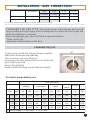
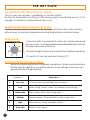
. Rating plate (located under the lower casing of the hob)
• All accessible parts of the hob will become hot while in operation. Always keep children
away from it.
• The hob should be given a quick clean after each use, to avoid the accumulation of
spillages and grease. If spillages are not removed, they will harden, and could cause the
production of smoke and unpleasant smells.
• When cooking with fats or oils, never leave gas burner unattended. Overheated fats or
oils can quickly catch fire.
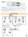
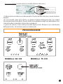
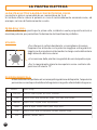
HOB FEATURES
MODELS 60 cm MODELS 75 cm

4
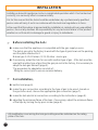
Before installing the hob :
make sure that the appliance is compatible with the gas supply source.
The hob is pre-set in the factory to work with the type of gas shown on the packing
and the plate attached to it.
Natural gas G 20-20 mbar / G 25-25 mbar : mains gas
if necessary, adapt the hob for use with another type of gas : if the hob must be
used with another type of gas than the gas pre-set in the factory, it is necessary to
adapt the hob gas burners (page 5).
The procedure for adaptation consists of :
. fitting the correct jets to ensure nominal delivery.
For installation,
built-in hob (page 6).
make the gas connection according to the type of gas to be used : based on
the gas to be used, choose the appropriate gas connection (page 7).
make the hob electrical connection according to the instructions (page 8).
adjusting the minimum flame of the taps : if necessary, adjust the minimum flame
of the taps by turning the by-pass screw (page 9).
INSTALLATION
Installing a domestic appliance can be a complicated operation which if not carried out
correctly, can seriously affect consumer safety.
It is for this reason that the task should be undertaken by a professionally qualified
person who will carry it out in accordance with the technical regulations in force.
In the event that this advice is ignored and the installation is carried out by an unqualified
person, the society declines all responsibility for any technical failure of the product
whether or not it results in damage to goods or injury to individuals.
All modification concerning the hob gas setting must be indicated on the rating
plate of the hob.

5
¤ = Factory setting: Natural gas = G20-20 mbar / G25-25 mbar
X = Gas setting possible according to installation Butane gas G30-29 mbar or Propane gas G 31-37 mbar
INSTALLATION: «GAS CONNECTION»
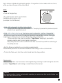
CHANGING THE JETS
To gain access to the jets, remove the pan supports,
and remove the burner cap and body,
Take a spanner and unscrew the jet.
According to the table below,
fit the correct jet for the
type of gas to be used,
Secure the jet tightly,
Replace the burner body, cap and the pan support.
JET
Each jet is designated by size.
SAG/ZAG 02G 52G03G13G
rabm02 rabm52rabm92
r
abm73
+3H2II.TACSE-TP-TI-BG
¤ XX
+3+E2II.TACRF
¤ ¤ XX
CHANGING THE GAS TYPE : the calorific power output and gas pressure will
vary according to the gas supply. Burner setting must be carried out once the gas and
electrical installation is complete.
When changing gas type, you must follow the procedure below :
. fit the correct jets,
. adjust the minimum flame on the taps.
SRENRUBBOH
yrailixuadipar-imesdipar
-artlu
dipar
sgniR4
saGrabmteJWkteJWkteJWkteJteJWk
* 02G 02 67 00,1 101 57,1 811 05,2 441 141 05,3
* 52G 52 67 09,0 101 06,1 811 03,2 441 141 02,3
03G920500,16657,10805,2496905,3
13G730500,16657,10805,2496905,3
* rabm52-52G-rabm02-02G:gnittesyrotcaF

6
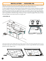
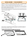
Both the worktop where the hob will be fitted and any adjacent kitchen furniture must be
made from heat resistant material and fixed with heat resistant adhesive.
If, when installing the hob, the lower hob face is adjacent to an area normally accessible
when handling or cleaning, fit a heatproof partition 1 cm below the base of the hob with
a 10X10 cm opening at the rear right-hand corner, to avoid any risk of scorching or damage.
A foam adhesive is supplied with the hob. Stick this seal under the edge of the body as
near as possible to the outer edge of the hob. Press round the edges of the hob, so that
the seal flattens out and ensures an air tight seal.
• BUILDING-IN
OPENING
10 X 10 cm
The body of the hob is fitted with 4 location holes to take the fixing brackets that secure
the hob in the unit. Place the 4 fixing brackets in such a way that the hob is placed
perfectly in the support unit.
SEAL
INSTALLATION : «BUILDING-IN»

7
INSTALLATION: «GAS CONNECTION»
The hob can be built-in ; it is in class 3 (in compliance with gas regulations EN 30.1.1) ;
adjoining furniture should not be higher than the level of the hob.
This appliance is not connected to an evacuation device for the products of combustion.
It must be installed and connected in compliance with the norms in force in the country of
installation. Particular attention should be given to the availability of ventilation.
The turnover of air necessary for combustion is a minimum of 2 m3/h per kW of power.
Gas connection should be carried out in compliance with the norms in force in the country
of installation. A stop tap, a regulator valve or a release valve for propane gas, should be
fitted to the gas supply pipe. Use only taps, regulator valves, connectors and flexible
hoses with the official mark of approval of the country of installation.
Built-in appliance
Butane Rigid - Flexible pipe with mechanical connectors (1) -
Propane Rigid - Flexible pipe with mechanical connectors (1) -
Natural Rigid - Flexible pipe with mechanical connectors (1) -
(1) on condition that the hose is accessible along the whole of its length it should be
located so it cannot be reached by naked flame or affected by combustion gases. Neither
should it be near hot parts of the hob nor anywhere where hot spillages could affect it.
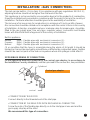
2 POSSIBLES MEANS OF CONNECTION :
Fit the appliance with the cylindrical or the conical gas adaptor, in accordance to
the installation Country standards, and then proceed to the connection, two possibilites:
• CONNECTION BY RIGID PIPE
Connect directly to the threaded end of the inlet pipe.
• CONNECTION BY FLEXIBLE PIPE WITH MECHANICAL CONNECTOR
Screw the nuts of the flexible pipe directly on to the inlet pipe at one end and the
gas supply stop tap at the other.
We recommend this type of connection.
Cylindrical
seal
conical
Conical gas adaptor

8
INSTALLATION: «ELECTRICAL CONNECTION»
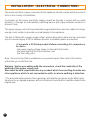
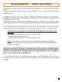
The mains electricity supply connected to the appliance should comply with the norms in
force in the country of installation.
Connection to the mains electricity supply should be through a socket with an earth
terminal, or through an intermediary switching device with a gap between contacts of
at least 3 mm.
The power supply unit must be protected by appropriate fuses and use cables of a large
enough cross section to provide a normal supply to the appliance.
The hob is fitted with a power supply cable* without plug which allow it to be connected
only to a power supply of 230 V between phases, or between phase and neutral.
• Connect to a 10/16 Amp socket. Before connecting, it is compulsory
to check :
. the power supply voltage shown on the electricity meter,
. the adjustment of the circuit breaker, and
. the fuse rating 10A.
Note : the socket must be reachable for any eventual repair. Take care of its location
at the time you install the hob.
Warning : before proceeding with the connection, check the continuity of the
earthing of the power supply unit.
We cannot be held responsible for any accident which has resulting from the use
of an appliance which is not connected to earth, or whose earthing is defective.
* The eventual replacement of the supplying cord must be carried on by the After Sales
Service or by an agreed engineer, with a cord whose characteristics must be similar to the
original one.

9
• SETTING THE IDLE FLAME
If you have changed the type of gas, it is important to verify the flame stability at the
minimum regulation.
«Gaining access to the by-pass screw»
To gain access to hob burner by-pass screws, remove the knobs from the control panel.
By-pass screw of the hob burner
Never loosen
the others screws !
REGULATING THE MINIMUM FLAME ON THE HOB BURNER
a) Natural gas :
. simply loosen the screw.
. switch on the burner and turn the knob to minimum.
. Turn the by-pass screw until a low flame is visible. Turn the control knob from
minimum to maximum position to check that it is satisfactory.
b) Butane-propane gas :
The by-pass screw should be screwed fully home, without being locked.
!
INSTALLATION: «REGULATING THE FLAME»

10
THE ULTRA-RAPID BURNER or "4 RINGS" BURNER, power rating 3,5 kW :
use this burner for bringing to boil, for cooking large quantities, and generally for all foods
requiring rapid cooking.
THE FAST BURNER, power rating 2,5 kW :
use the large burner for all foods requiring rapid cooking.
THE SEMI-FAST BURNER, power rating 1,75 kW or THE AUXILIARY BURNER, power
rating 1kW :
it is ideal for stewing, sauces and slow cooking.
The pan supports fitted on the 1,75 kW burners are working as Mijorose when the burner
is set on low rate.
On the slow setting, the flame only comes into contact with the cast iron burner cap. This
is ideal for slow cooking, as the heat is evenly distributed under the pan and food doesn't
dry out or stick to the bottom of the pan.
On the high position, the flames heat directly the pan allowing all cookings on quick gas.
For a proper use of the burners, choose pans which match the dimensions given below :
* Ultra-rapid or "4 Rings" Ø 18 cm and more
* Rapid Ø 16 to 18 cm
* Semi-fast Ø 12 cm
* Auxiliary Ø 10 cm
SOME TIPS ....
• Pans with curved, ridged or warped bottoms are not recommended.
• Centre the pan on the "pan support".
• Do not place the same pan on two burners.
• Avoid boiling food too intensely. Food is not cooked any more quickly this way. In fact,
it is subjected to severe agitation, which may cause the food to lose some of its flavour.
• To save gas, make sure that the flames do not overlap the bottom of the pan.
• Do not use the gas burner with an empty pan.
WARNING :
. when the burners are not in service, the general gas supply tap should always be
turned off.
. the use of a steak-grid is forbidden. The high temperatures reached on the hob
surface will give to the glass a thermic shock which will lead to an irreversible
brittleness.
THE GAS BURNER

11
Each burner is fitted with automatic ignition. The ignition can be made with one hand,
while you have the pan in the other hand.
USE :
• Turn on the gas tap,
• A symbol next to each control knob
indicates which burner is lit.
(example: front left burner)
• Hob with automatic ignition integrated :
• Press and turn the knob to position "" keeping it pressed to produce sparks
which in turn ignite the burner.
• Hob with safety device on the burner and automatic ignition integrated :
The thermocouple fast safety is a device allowing the automatic cut-out of the gas
supplying on the burner, in case the flame dies out accidentally.
• Press and turn the knob to position "high flame" keeping it pressed to
produce sparks which in turn ignite the burner.
Keep the pressure on the control knob a few seconds to permit the releasing of
the safety device.
• Set the flame according to your cooking requirements.
Intermediate positions are available between the settings on the control knob.
• To turn the flame out, turn the control knob back to stop position.
Please note :
. If there is a power cut, the burner can be ignited by pressing in and turning the knob to
position "high flame" and holding a naked flame to the burner.
Caution:
the heating surface clearly get hot while operating, so make sure that small children are
kept well away from the hob.

12
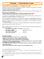
THE HOT PLATE
THE SPEED PROTECTED HOT PLATE - 1500 W.
This is a cast-iron hot plate, controlled by a 7 position switch.
An internal thermostat cuts off part of the power supply if overheating occurs. (if, for
example, a hot plate is working without a pan on it).
BEFORE USING THE ELECTRICAL HOT PLATE :
• Before using the electric hot plate for the first time, let it heat up for a few minutes,
without a pan, at maximum temperature to allow the protective coating to harden.
HOW TO USE :
• For best results, it is advisable to start on the maximum heat and
then turn back to an intermediate temperature taking into account
the type and volume of the food.
• An indicator light comes on to show that the hot plate is operating.
• To switch off, turn the knob back to point "O".
DIFFERENT TEMPERATURE SETTINGS :
Below are a few examples which are given as guidelines. When you become more
familiar with the appliance, you will be able to choose settings to suit your own
personal tastes and requirements.
snoitisoP
.....spitemoS
1wolyreV
....etalocohcdnarettubtlem,tohhsidapeekoT
2woL
...sggedehcaop,gniddupecir,s
wets,secuas,gnikoocwolS
3yletaredoM
....retawgniliob,tiurf,sdoofnezorf,snaeB
4muideM
....hsif,seperc,atsap,
selbategevhserf,selppademaetS
5hgiH
....skaets,settelemo,gnikoocesnetnieroM
6hgihyreV
...gniyrf,spohc,skaet
S

13
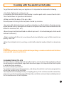
Cooking with the electrical hot plate
To get the best results from your appliance it is important to observe the following :
• Use thick, flat-based cooking vessel :
a completely flat base prevents overheating to certain parts which causes food to stick.
Thick metal allows for good heat distribution.
• Make sure that the base of the pan is dry :
this will prevent sticking to the hot plate caused by moisture.
• Use pans with a diameter large enough to completely cover the hot plate, otherwise energy
will be wasted and any spillages will cause the hot plate to become stained and will become
difficult to maintain (rust, etc.).
• Never leave a hot plate switched on without a pan on it : it can be damaged, which would
reduce its efficiency.
• When cooking with fat or oil, never leave the hob unattented, very hot fats and oils can
quickly catch fire.
• When the hot plate is hot, avoid any contact with materials made of plastic or aluminium
foil.
Caution :
the heating surfaces clearly get hot while operating, so make sure that small children
are kept well away from the hob.
CLEANING THE HOT PLATE
To burn off any cooking deposits heat the hob for a short time. After switching off and
the hot plate has cooled down, wipe it with absorbent paper. It is important that the hot plate
is protected from moisture.
Do not use abrasive products.
To maintain and preserve its appearance, rub a drop of neutral oil, such as sewing machine
oil into the surface of the hot plate.
The hot plate should always be dry, or slightly greasy. If it is not to be used for some time,
remove any rust using emery paper followed by a suitable commercially available product
for the maintenance of soil hotplates.

14
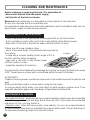
CLEANING AND MAINTENANCE
30˚
maxi
Racloir
Scraper
Before cleaning or removing the hob, it is imperative to :
• disconnect the hob from the mains supply,
• let all parts of the hob cool down.
Never use harsh abrasives, scouring pads or sharp objects to clean the hob.
Do not use a sponge that it is excessively wet.
It is advisable to keep away from the hob all substances which are liable to melt, such as
plastic items, sugar, or sugar-based products.
MAINTENANCE OF THE GLASS HOB
. Place a few drops of the specialised cleaning products on the hob surface.
. Rub any stubborn stains with a soft cloth or with slightly damp kitchen paper.
. Wipe with a soft cloth or dry kitchen paper until the surface is clean.
If there are still some stubborn stains :
. place a few more drops of specialised cleaning fluid on
the surface,
. scrape with a scraper, holding it at an angle of 30° to
the hob, until the stains disappear.
. wipe with a soft cloth or dry kitchen paper
until the surface is clean.
. repeat the operation if necessary.
A scraper with a razor blade will not damage the surface, as long as it is kept at an angle
of 30°. Never leave a scraper with a razor blade within the reach of children.
A FEW HINTS :
Frequent cleaning leaves a protective layer which is essential to prevent scratches and
wear.
Make sure that the surface is clean before using the hob again.
To remove marks left by water, use a few drops of white vinegar or lemon juice. Then
wipe with absorbent paper and a few drops of specialised cleaning fluid.
MAINTENANCE OF THE HOB
. Enamelled steel hob : when the hob has cooled completely, simply clean the enamelled
hob with soapy water, rinse and wipe with a clean dry cloth. If you clean the enamelled
hob when it is hot, you may tarnish it.
. Stainless steel : clean with soapy water, rinse and dry. You can use a special product
to clean stainless steel which is available from various retail outlets. Place a few drops of
the specialised cleaning products on the hob surface.

15
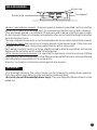
Pan support
Burner head
Burner cap
• Burner caps and pan supports : the pan support is made of enamelled cast-iron and the
burner cap is made of enamelled steel, for a maximal protection and an easy cleaning.
They are simply placed. Just lift them off and clean with a damp, slightly soapy sponge.
Do not immerse them in cold water immediately after use to avoid cracking the enamel
from the thermal shock.
The use of abrasive cleansers is not recommended as they scratch and dull the enamel.
• The burner head : the burner cap is simply placed on the burner head. If the holes are
clogged, brush the caps using soapy water and dry with a clean cloth.
Each burner is simply layed on a flange slightly bossed to drain the overflows far from the
flame and the hot areas which make cleaning easier.
• After cleaning of each element, it is important to wipe them correctly and care of fitting
them rightly in their initial position. The re-fitting must be perfect because a bad positioning
can bring serious anomalies in the combustion.
Warning : be careful, not to let any water get into the burners.
THE KNOBS
• For thorough cleaning, the control knobs can be removed by pulling them upwards.
Only clean with soapy water and dry well before replacing them.
• Do not try to pull the watertightness rings. They are originally fitted and must not be
pulled out.
THE GAS BURNERS

16
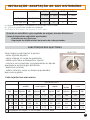
APERTURA IMBALLO DELL'APPARECCHIO
Una volta aperto l'imballo del piano di cottura, troverete :
• un sacchettino contenente :
- nuovi iniettori per un eventuale cambio di gas, se necessario,
- delle staffette di fissaggio con viti per bloccare la placca sul piano di lavoro,
- secondo il modello, un raccordo cilindrico e/o un raccordo conico con giunzione,
essendo esso stesso obbligatorio per l'installazione del piano.
LEGGERE ATTENTAMENTE LE ISTRUZIONI INCLUSE IN QUESTO LIBRETTO.
Vi danno importanti indicazioni sulla sicurezza d'installazione, d'impiego e di pulizia, ed
anche qualche consiglio per un ottimo utilizzo del piano di cottura. Conservare con cura
questo documento per consultazione ulteriore e notare qui sotto, prima dell'installazione
del piano, il numero di serie dell'apparecchio, nel caso di un ulteriore richiesta d'intervento
del servizio di assistenza.
RACCOMANDAZIONI
Apertura imballo dell'apparecchio ....................................................... 16
Raccomandazioni............................................................................... 16
Presentazione .................................................................................... 17
• ALLACCIAMENTO
"PARTE A GAS"
* Locale di installazione ..................................................................... 18
* Collegamento all'alimentazione ........................................................ 19
* Cambio di gas ................................................................................. 20
* Regolazione del minimo................................................................... 21
COLLOCAMENTO ............................................................................. 22
PARTE ELETTRICA ........................................................................... 23
• UTILIZZO
I bruciatori a gas ................................................................................ 24
Uso dei bruciatori ............................................................................... 25
La piastra elettrica - consigli di uso ............................................... 26-27
Manutenzione ............................................................................... 28-29
INDICE
Tutte queste caratteristiche sono indicative, la società perseguendo una politica di aggiorna-
mento tecnico-qualitativo dei prodotti, si riserva il diritto di apportarvi modifiche migliorative.
Dichiarazione di conformità : questo apparecchio, nelle parti destinati a venire a contatto
con sostanze alimentari, è conforme alla prescrizione della dir. CEE 89/109 e al D.L. di
attuazione N° 108 del 25.01.92.
Questo apparecchio è conforme alle direttive 89/336/CEE, 73/23/CEE,
90/396/CEE e modifiche successive.

17
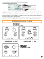
Placca segnaletica (situata sotto la cassetta inferiore del piano).
• Tutti le parti accessibili sono calde durante il funzionamento del piano, tenere lontano i
bambini.
• Si raccomanda, dopo ogni utilizzo, un minimo di pulizia dell'apparecchio, per evitare
l'accumulo di sporcizia e grassi. Questi, infatti, ricuocerebbero ad ogni uso dell'apparecchio,
carbonizzandosi e liberando fumi ed odori sgradevoli.
• I grassi di cottura o l'olio caldo provocano degli schizzi. Badare di non allontanarsi
dall'apparecchio, tali sostanze possono infiammarsi.
PRESENTAZIONE
MODELLI 60 CM MODELLI 75 CM

18
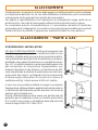
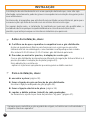
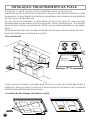
ALLACCIAMENTO
ISTRUZIONI PER L'INSTALLATORE
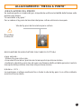
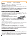
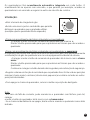
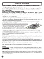
LOCALE DI INSTALLAZIONE : l'utilizzo di un apparecchio
di cottura a gas produce calore e umidità nel locale in cui è
installato. Vogliate assicurare una buona aerazione del lo-
cale mantenendo aperti gli orifizi di ventilazione naturale o
installando una cappa di aspirazione con condotto di scarico
(fig. 1-2). Un utilizzo intensivo e prolungato dell'apparecchio
puó necessitare di un'aerazione supplementare, per
esempio l'apertura di una finestra o un'aerazione più effi-
cace aumentando la potenza di aspirazione meccanica se
essa esiste. Nel caso in cui l'apparecchio fosse sprovvisto
di termocoppia (dispositivo di sicurezza) la presa di
ventilazione di fig. 1 dovrà essere di 200 cm² minimo.
In caso non sia possibile installare la cappa è necessario
l'impiego di un elettroventilatore applicato alla parete esterna
o alla finestra dell'ambiente purché esistano nel locale le
aperture per l'entrata di aria.
Questo elettroventilatore deve avere una portata tale da
garantire, per un ambiente cucina un ricambio orario d'aria
di 3-5 volte il suo volume. L'installatore deve attenersi alle
norme in vigore UNI-CIG 7129 e 7131.
Il collegamento e la messa in funzione degli apparecchi elettrodomestici nel loro ambiente
è un'operazione delicata che, se non viene effettuata correttamente, puó causare delle
conseguenze anche gravi per la sicurezza dei consumatori.
Per questo è importantissimo che l'operazione di collegamento venga svolta da un
professionista, che potrà di conseguenza attenersi alle norme tecniche in vigore.
Se nonostante questa raccomandazione, il consumatore deciderà di realizzare
personalmente il collegamento, la società non sarà ritenuta responsabile per eventuali
incidenti tecnici sul prodotto, e neppure per eventuali incidenti a cose o persone.
ALLACCIAMENTO : "PARTE A GAS"

19
COLLEGAMENTO ALL'ALIMENTAZIONE - il collegamento dell'apparecchio alla
tubazione o alla bombola del gas dovrà essere effettuato come prescritto dalle Norme
UNI-CIG 7129 e 7131, solo dopo essersi accertati che esso è regolato per il tipo di gas
con cui sarà alimentato. In caso contrario eseguire le operazioni indicate nel paragrafo
"Cambio di gas" pagina 38. Nel caso di alimentazione con gas liquido, da bombola,
utilizzare regolatori di pressione conformi alla Norme UNI-CIG 7432.
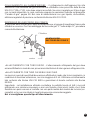
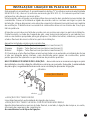
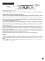
MONTAGGIO DEL RACCORDO GAS CONICO
A seconda delle norme del Paese di installazione, si prega di scegliere il raccordo
cilindrico o conico. Per l'assemblaggio del raccordo gas "C" sulla rampa "A", procedere
come da illustrazione.
• ALLACCIAMENTO CON TUBO RIGIDO - L'allacciamento all'impianto del gas deve
essere effettuato in modo da non provocare sollecitazioni di alcun genere all'apparecchio.
• ALLACCIAMENTO CON TUBO FLESSIBLE IN ACCIAIO
La messa in opera di questi tubi deve essere effettuata in modo che la loro lunghezza, in
condizioni di massima estensione, non sia maggiore di 2 mt. Utilizzare esclusivamente
tubi conformi alla Norma UNI-CIG 9891 e guarnizioni di tenuta conformi alla Norma
EN 549.
Importante : ad installazione ultimata controllare la perfetta tenuta di tutti i raccordi
utilizzando una soluzione saponosa e mai una fiamma. Assicurarsi inoltre che il tubo
flessible non possa essere a contatto con una parte mobile del modulo da incasso (es.
cassetto) e che non sia situato in luoghi dove possa essere danneggiato.
Noi vi consigliamo questo tipo di allacciamento.
Cilindrico
guarnizione
conico
MONTAGGIO DEL
RACCORDO GAS CONICO

20
Il piano viene regolato presso la casa produttrice per il funzionamento al tipo di gas indicato
sull'imballo e riportato sull'etichetta applicata sull'apparecchio. In caso di funzionamento
con un altro gas, é necessario adattare l'apparecchio. Tale adattamento consiste nel
mettere l'iniettore adatto (che assicura l'erogazione nominale), e regolare il minimo.
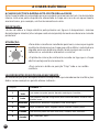
• SOSTITUZIONE DEGLI INIETTORI -
Per accedere agli iniettori, eseguire nell'ordine le seguenti
operazioni:
- asportare le griglie e i bruciatori,
- introdurre una chiave per tubazioni e,
- svitare l'iniettore e sostituirlo con quello adatto
al tipo di gas disponibile.
Il rimontaggio si effettua ripetendo l'operazione all'inverso.
ALLACCIAMENTO : "CAMBIO DI GAS"
INIETTORE
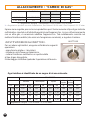
¤ = Regolazione d'origine : Gas Naturale = G20-20 mbar / G25-25 mbar
X = Regolazione possibile secondo l'installazione, Gas Butano G30-29 mbar / Gas Propano G 31-37 mbar
Ogni iniettore è identificato da un segno di riconoscimento.
SAG/ZAG 02G 52G03G13G
rabm02 rabm52rabm92
r
abm73
+3H2II.TACSE-TP-TI-BG
¤ XX
+3+E2II.TACRF
¤ ¤ XX
IROTAICURB
orailisuaodipar-imesodipar
-artlu
odipar
4
anoroc
saGrabmerotteinI
WkI erotteinWkerotteinIWk.jnIerotteinIWk
* 02G 02 00,1 67 101 57,1 811 05,2 441 441 05,3
* 52G 52 09,0 67 101 06,1 811 03,2 441 441 02,3
03G9200,1056657,10805,2494905,3
13G7300,1056657,10805,2494905,3
* rabm52-52G-rabm02-02G:enigiro'denoizalogeR
La pagina sta caricando ...
La pagina sta caricando ...
La pagina sta caricando ...
La pagina sta caricando ...
La pagina sta caricando ...
La pagina sta caricando ...
La pagina sta caricando ...
La pagina sta caricando ...
La pagina sta caricando ...
La pagina sta caricando ...
La pagina sta caricando ...
La pagina sta caricando ...
La pagina sta caricando ...
La pagina sta caricando ...
La pagina sta caricando ...
La pagina sta caricando ...
La pagina sta caricando ...
La pagina sta caricando ...
La pagina sta caricando ...
La pagina sta caricando ...
La pagina sta caricando ...
La pagina sta caricando ...
La pagina sta caricando ...
La pagina sta caricando ...
-
 1
1
-
 2
2
-
 3
3
-
 4
4
-
 5
5
-
 6
6
-
 7
7
-
 8
8
-
 9
9
-
 10
10
-
 11
11
-
 12
12
-
 13
13
-
 14
14
-
 15
15
-
 16
16
-
 17
17
-
 18
18
-
 19
19
-
 20
20
-
 21
21
-
 22
22
-
 23
23
-
 24
24
-
 25
25
-
 26
26
-
 27
27
-
 28
28
-
 29
29
-
 30
30
-
 31
31
-
 32
32
-
 33
33
-
 34
34
-
 35
35
-
 36
36
-
 37
37
-
 38
38
-
 39
39
-
 40
40
-
 41
41
-
 42
42
-
 43
43
-
 44
44


Hoover HGF 6040 B Manuale utente
- Categoria
- Piani cottura
- Tipo
- Manuale utente
- Questo manuale è adatto anche per
Documenti correlati
Altri documenti
-
Candy PV 750 Manuale del proprietario
-
Candy PV750SN Manuale utente
-
ROSIERES TCS 40 IN Manuale del proprietario
-
Candy PSA 640/2 FX Manuale utente
-
-
-
-
-
Zerowatt ZHW6LCX Manuale utente