
Viale Vicenza, 14
36063 Marostica VI - Italy
www.vimar.com
46241.H04
49401069A0 02 1701
1 Introduction
1.1 Summary
Based on the most advanced SOC technology and embedded system in
the eld, this series of the NVR adopt the new designed human interface
and support the smart management of the IP camera and the record
search of slice. This series of the NVR which are powerful and easy to
use are provided with excellent image quality and stable system. They
are centralized monitoring management products with high performance
and high quality specially designed for network video monitoring eld.
This series of the NVR can be widely used to security system of banks
at home and abroad, schools, intelligent mansions, trafc, environmental
protection, supermarkets, petrol service stations, residential quarters and
factories and so on.
1.2 Front Panel Descriptions
The following descriptions are for reference only.
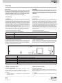
1.3 Descrizione del pannello posteriore
In questa sezione prendiamo ad esempio soltanto una parte dei pannelli
posteriore per presentare le loro interfacce e le loro connessioni. Le
interfacce e le posizioni delle interfacce valgono solo come riferimento.
Far riferimento all’apparecchiatura in dotazione.
Nome/Name Descrizioni/Descriptions
PORTE PoE / PoE PORT RJ45x4
48 Vdc Ingresso alimentazione 48 Vdc / 48 Vdc power input
LAN Porta di rete / Network port
HDMI Collegamento al dispositivo di visualizzazione ad alta denizione / Connect to high denition display device
USB Connessione di dispositivo di memoria USB o mouse USB / Connect USB storage device or USB mouse
AUDIO OUT Uscita audio, connessione agli altoparlanti / Audio output; connect to sound box
2 Guida all’utilizzo di base
2.1 Avvio e spegnimento
Prima di collegare l’unità all’alimentazione, vericare che tutti i
collegamenti siano stati eseguiti correttamente. Un corretto avvio e
arresto è estremamente importante per la durata del dispositivo.
2.1.1 Avvio
1- Collegare il dispositivo di visualizzazione in uscita all’interfaccia
VGA/HDMI del NVR.
1.3 Rear Panel Descriptions
Here we only take a part of real panels for example to introduce their
interfaces and connections. The interfaces and locations of the interfaces
are only for references. Please take the real object as the standard.
2 Basic Operation Guide
2.1 Startup & Shutdown
Please make sure all the connections are done properly before you
power on the unit. Proper startup and shutdown are crucial to expending
the life of your device.
2.1.1 Startup
1- Connect the output display device to the VGA/HDMI interface of the
NVR.
Name/Name Descriptions/Descriptions
REC (Registra) Durante la registrazione la luce è blu / When recording, the light is blue
Net (Rete) Quando è attivo l'accesso alla rete la luce è blu / When access to network, the light is blue
Alimentazione (Power) Spia di alimentazione, quando è collegata la luce è blu / Power indicator, when connection, the light is blue
Fn (Funzione) Nessuna funzione disponibile al momento / No function temporarily
AUDIO
OUT
Description
4-channel NVR, Pentaplex function, H.265 video compression, 4 channels
Real Time (5 Mpx max), professional HDD 1 TB, SATA x 1 max 6 Tera, 1 out
audio connection, 2 USB, HDMI, built-in 4-port PoE switch with Plug&Play
configuration, remote control, QRCODE, privacy masking, ONVIF protocol,
CVM software.
Descrizione
NVR a 4 canali, funzione Pentaplex, compressione H.265, 4 canali Real
Time (5 Mpx max), HDD professionale da 1 TB, SATA x 1 max 6 Tera, con-
nessioni audio 1 out, 2 USB, HDMI, switch PoE integrato da 4 porte con
configurazione Plug&Play, controllo e visione remota, QRCODE, masche
-
ratura di privacy, motion, protocollo ONVIF, software CVM.
1 Introduzione
1.1 Riepilogo
Basata sulle tecnologie SOC e sui sistemi embedded più all’avanguardia
del settore, questa serie di NVR adotta l’ultimo design di interfaccia utente
e supporta la gestione intelligente delle telecamere IP e della ricerca per
fascia oraria, delle registrazioni. Questa serie di NVR, di grande potenza
e semplicità di utilizzo, è dotata di un’eccellente qualità dell’immagine e
di un sistema stabile. Contiene prodotti per la gestione centralizzata del
monitoraggio ad elevate prestazioni e qualità, progettata appositamente
per il settore del monitoraggio di video di rete.
Questa serie di NVR è applicabile ai sistemi di sicurezza per banche,
scuole, impianti domotici, trafco, tutela dell’ambiente, supermercati,
stazioni di rifornimento, zone residenziali, stabilimenti industriali, ecc.
1.2 Descrizione del pannello anteriore
Le seguenti descrizioni valgono solo come riferimento.

Viale Vicenza, 14
36063 Marostica VI - Italy
www.vimar.com
46241.H04
49401069A0 02 1701
2.1.2 Spegnimento
1- Fare clic su Start
Shutdown (arresto) e comparirà la nestra di
arresto. Selezionare “Shutdown” (“Arresto”) all’interno della nestra.
Dopo un momento di attesa, l’unità si spegnerà facendo clic sul
pulsante “OK”.
2- Scollegare l’alimentazione.
2.2 Controllo del mouse
• Controllo del mouse nell’interfaccia Anteprima Live e
Riproduzione
Nell’interfaccia Anteprima Live e Riproduzione, fare doppio clic su
qualsiasi nestra della telecamera per visualizzare la nestra in modalità
a schermo singolo; fare nuovamente doppio clic per ripristinare le
dimensioni precedenti. Nell’interfaccia Anteprima Live e Riproduzione,
se le interfacce vengono visualizzate a schermo intero, portare il mouse
sulla parte inferiore dell’interfaccia per far apparire una barra degli
strumenti. La barra degli strumenti scomparirà in automatico spostando
il mouse in un’altra posizione per un po’ di tempo; portare il mouse sulla
destra dell’interfaccia per far apparire un pannello, il pannello scomparirà
in automatico spostando il mouse in un’altra posizione.
• Controllo del mouse nell’immissione testo
Portare il mouse sulla casella di immissione testo, quindi fare clic sulla
casella. La tastiera di immissione comparirà in automatico.
Nota:
Il mouse è lo strumento predenito per tutte le operazioni, salvo diversa
indicazione.
3 Procedura guidata e interfaccia
principale
3.1 Procedura guidata per l’avvio
Le icone del disco verranno visualizzate in alto
nell’interfaccia di avvio. È possibile visualizzare
il numero e lo stato di ciascun disco in maniera
veloce e intuitiva attraverso queste icone (
: disco
assente;
: disco non disponibile; : disco RW
disponibile).
È possibile congurare rapidamente l’NVR tramite la
procedura guidata d’impostazione per far funzionare
l’NVR normalmente. È necessario congurare la
procedura guidata quando l’NVR viene avviato per
la prima volta (oppure fare clic su “Skip” (Salta) per
annullare la procedura guidata la volta successiva).
Fare clic su “Wizard Setup” (Procedura Guidata
Impostazione) per iniziare la procedura guidata. Le
fasi di impostazione sono le seguenti.
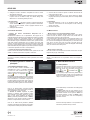
1- Accesso al sistema. Impostare la propria
password o utilizzare quella predenita quando
viene utilizzata la procedura guidata per la prima
volta (il nome utente predenito del sistema è
admin; la password predenita di admin è 123456);
selezionare il nome utente di accesso e inserire la
password corrispondente la volta successiva
Fare clic su “Edita Security Question” (Modica
domanda di sicurezza) per impostare le domande e
le risposte di sicurezza per la password dell’admin.
2.1.2 Shutdown
1- Click StartShutdown to pop up the Shutdown window. Select
“Shutdown” in the window. The unit will power off after a while by
clicking “OK” button.
2- Disconnect the power.
2.2 Mouse Control
• Mouse control in Live Preview & Playback interface
In the live preview & playback interface, double click on any camera
window to show the window in single screen mode; double click the
window again to restore it to the previous size.
In the live preview & playback interface, if the interfaces display in full
screen, move the mouse to the bottom of the interface to pop up a tool
bar. The tool bar will disappear automatically after you move the mouse
away from it for some time; move the mouse to the right side of the
interface to pop up a panel and the panel will disappear automatically
after you move the mouse away from it.
• Mouse control in text-input
Move the mouse to the text-input box and then click the box. The input
keyboard will pop up automatically.
Note:
Mouse is the default tool for all operations unless an exception as
indicated.
3 Wizard & Main Interface
3.1 Startup Wizard
The disk icons will be shown on the top of the startup
interface. You can view the number and status of
each disk quickly and conveniently through these
icons (
: no disk; : unavailable disk; : RW
available disk).
You can quickly congure the NVR by wizard setup to
make the NVR work normally. You must congure the
wizard if you start the NVR for the rst time (or click
“Skip” to cancel the wizard next time).
Click “Wizard Setup” to start wizard. The setting steps
are as follows.
1- System Login. Set your own password or use
the default when you use the wizard for the rst time
(the default username of the system is admin and
the default password of admin is 123456); select
the login username and enter the corresponding
password next time.
Click “Edit Security Question” to set questions and
answers for password security of admin.
2- Collegare il mouse e accendere. Il dispositivo si avvia e il LED di
alimentazione diventa blu.
3- Comparirà una procedura guidata (selezionare la lingua del display
la prima volta che si utilizza il NVR). Per ulteriori dettagli, fare
riferimento a 3.1 Procedura guidata per l’avvio.
2- Connect with the mouse and power. The device will boot and the
power LED would turn blue.
3- A WIZARD window will pop up (you should select the display
language the rst time you use the NVR). Refer to 3.1 Startup Wizard
for details.

Viale Vicenza, 14
36063 Marostica VI - Italy
www.vimar.com
46241.H04
49401069A0 02 1701
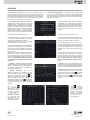
2-Congurazione di data e ora La data e l’ora del sistema devono
essere impostate se la procedura guidata viene utilizzata per la prima
volta. Fare riferimento alla gura seguente. Impostare il fuso orario, l’ora
del sistema, il formato della data e il formato dell’ora. Il DST sarà abilitato
per impostazione predenita se il fuso orario selezionato comprende
DST. Fare clic su “Next” (Avanti) per continuare.
Introduzione Porta Ethernet interna (PoE):
Se si utilizzano le porte di rete PoE, lo stato “onli-
ne” della porta Ethernet interna verrà mostrato
sull’interfaccia. Fare riferimento alla foto.
La porta Ethernet interna è la porta che collega
tutte le porte PoE con il sistema NVR.
Le porte PoE sono disponibili se la porta Ethernet
interna è in linea (online); se non è in linea, tutte le
porte PoE non saranno disponibili, questo potreb-
be essere dovuto al malfunzionamento della porta
Ethernet interna.
L’indirizzo IP e la subnet mask della porta Ethernet
interna possono essere modicati per rendere la
porta nello stesso segmento di rete delle teleca-
mere IP collegate direttamente alle porte PoE dell’
NVR (non è consigliabile modicare l’indirizzo
IP e la maschera di sottorete della porta Ether-
net interna).
3- Impostazioni di rete. Selezionare “Obtain an
IP address automatically” (Ottenere un indirizzo IP
automaticamente) e “Obtain DNS automatically”
(Ottenere DNS automaticamente) per ottenere
l’indirizzo IP e DNS automaticamente, o immettere
manualmente l’indirizzo IP, maschera di sottorete,
gateway, DNS preferito e DNS alternativi.
Immettere la porta HTTP, la porta RTSP e la porta
Server. Fare clic su “Next” (Avanti) per continuare.
2- Date and Time Conguration. The date and time of the system need
to be set up if you use the wizard for the rst time. Refer to the following
gure. Set the time zone, system time, date format and time format. The
DST will be enabled by default if the time zone selected includes DST.
Click “Next” to continue.
3- Network Settings. Check “Obtain an IP address
automatically” and “Obtain DNS automatically”
to get the IP address and DNS automatically, or
manually input IP address, subnet mask, gateway,
preferred DNS and alternate DNS. Input the HTTP
port, RTSP port and Server port. Click “Next” to
continue.
Internal Ethernet Port Introduction (PoE):
If you use the NVR with the PoE network ports,
the online state of the internal ethernet port will be
shown on the interface. Refer to the picture.
The internal ethernet port is the port which con-
nects all the PoE ports with the NVR system. The
PoE ports are available if the internal ethernet port
is online; if it is ofine, all the PoE ports will be
unavailable, may be the internal ethernet port is
broken.
The IP address and subnet mask of the internal
ethernet port can be changed to make the port in
the same network segment with the IP cameras
which directly connect to the PoE ports of the NVR
(it is not recommended to change the IP ad-
dress and subnet mask of the internal ethernet
port).
4- QRCode. È possibile scansionare il QRCode
attraverso l’applicativo client installato nel telefono
cellulare o nel PAD per accedere istantaneamente.
Per maggiori dettagli vedere il paragrafo 4.2
Sorveglianza Client Mobile.
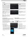
5- Aggiunta Telecamera. Fare clic su
“Refresh” (Aggiorna) per aggiornare l’elenco
delle telecamere IP online che si trovano nella
stessa rete locale dell’NVR e fare clic
per
aggiungere la telecamera cercata. Fare clic su
“Add All” (Aggiungi Tutto) per aggiungere le
telecamere nell’elenco. Fare clic
per eliminare
la telecamera aggiunta. Fare clic su “Delete All”
(Elimina tutto) per eliminare tutte le telecamere
aggiunte.
4- QRCode. You can scan the QRCode through
mobile client which is installed in the mobile phone
or PAD to log in the mobile client instantly. Please
refer to 4.2 Mobile Client Surveillance for details
.
5- Add Camera. Click “Refresh” to refresh the list
of online IP cameras which are in the same local
network with NVR and then click to add the
searched camera. Click “Add All” to add all the
cameras in the list. Click
to delete the added
camera. Click “Delete All” to delete all the added
cameras.
Fare clic su
per modicare la
telecamera IP cercata
come mostrato in basso
a sinistra. Immettere
il nuovo indirizzo IP,
la subnet mask, il
gateway, il nome utente
e la password della
telecamera. Fare clic
sul pulsante “OK” per
salvare le impostazioni.
Click to edit the
searched IP camera
as shown on the below
left. Input the new IP
address, subnet mask,
gateway, username
and the password of the
camera. Click “OK” to
save the settings.

Viale Vicenza, 14
36063 Marostica VI - Italy
www.vimar.com
46241.H04
49401069A0 02 1701
7- Impostazioni registrazione. Sono
disponibili due modalità di registrazione:
automatica e manuale.
Automatica: Selezionare una modalità
automatica nell’interfaccia come indicato di
seguito, quindi fare clic sul pulsante “OK” per
salvare le impostazioni.
Fare clic su
per modicare la telecamera
aggiunta come mostrato in alto a destra.
Immettere il nuovo nome della telecamera,
l’indirizzo IP, la porta, il nome utente e la
password della telecamera. È possibile fare
clic sul pulsante “Test” (Prova) per vericare
l’esattezza delle informazioni immesse. Fare clic
sul pulsante “OK” per salvare le impostazioni.
È possibile modicare il nome della telecamera
IP solo quando la telecamera aggiunta è online.
Fare clic su “Next” (Avanti) per continuare.
6- Impostazioni disco. È possibile visualizzare
il numero disco, la capacità disco dell’NVR e il
numero di serie, lo stato R&W del disco. Fare clic
su “Formatting” (Formattazione) per formattare il
disco. Fare clic su “Next” (Avanti) per continuare.
Manuale: Impostare “Sensor Record”
(Registrazione Sensore), “Motion Record”
(Registrazione Movimento) e “Schedule Record”
(Registrazione Programmazione) di ciascuna
telecamera. Fare clic sul pulsante “OK” per
salvare le impostazioni.
Click to edit the added camera as shown
on the above right. Input the new camera
name, IP address, port, username and
the password of the camera. You can click
“Test” to test the effectiveness of the input
information. Click “OK” to save the settings.
You can change the IP camera name only
when the added camera is online. Click “Next”
to continue.
6- Disk Settings. You can view the disk
number, disk capacity of the NVR and
serial number, R&W status of the disk. Click
“Formatting” to format the disk. Click “Next”
to continue.
Manual: Set the “Sensor Record”, “Motion
Record” and “Schedule Record” of each
camera. Click “OK” to save the settings.
7- Record Settings. Two record modes are
available: auto and manual.
Auto: Select one auto mode in the interface
as shown below and then click “OK” button to
save the settings.
4 Congurazione NAT
Fare clic su StartSettingsNetworkNAT (Start/Impostazioni/Rete/
NAT) per passare all’interfaccia per la congurazione NAT. Selezionare
il pulsante “Enable” (Abilita), quindi selezionare l’indirizzo server NAT
(nat.autonat.com per impostazione predenita). Fare clic sul pulsante
“Apply” (Applica) per salvare le impostazioni.
4.1 Visualizzazione dello stato di rete
Fare clic su StartSettingsNetworkNetwork Status (Start/Settings/
Rete/Stato rete) per visualizzare lo stato di rete o fare clic sull’icona
sulla barra degli strumenti in fondo all’interfaccia di anteprima live per
visualizzare facilmente lo stato di rete.
4.2 Sorveglianza remota
Sorveglianza Client Mobile
1- Attivare la funzione NAT nell'NVR.
2- Scaricare e installare il client mobile “SuperLive
Plus” in un dispositivo mobile con sistema
operativo Android o iOS.
3- Eseguire il client mobile, andare all'interfaccia
"Add Device" (Aggiungi dispositivo),
quindi fare clic su
per scansionare il
QRCode dell'NVR (Andare al percorso
StartSettingsSystemInformationBasic
(Start/Impostazioni/Sistema/Informazioni/
Base) per visualizzare il QRCode dell'NVR).
4- Dopo aver scansionato il QRCode con
successo, immettere la password di login nel
client mobile.
4.2 Remote Surveillance
Mobile Client Surveillance
1- Enable NAT in the NVR.
2- Download and install the mobile client
“SuperLive Plus” into the mobile device with
the Android or iOS system.
3- Run the mobile client, go to the “Add Device”
interface and then click
to scan the
QRCode of the NVR (Go to StartSettings
SystemInformationBasic to view the
QRCode of the NVR).
4- After scanning the QRCode successfully, input
the login password to log in mobile client.
4 NAT Conguration
Click StartSettingsNetworkNAT to go to the interface for NAT
conguration. Check “Enable” and then select the NAT server address
(nat.autonat.com by default). Click “Apply” to save the settings.
4.1 View Network Status
Click StartSettingsNetworkNetwork Status to view the network
status or click
on the tool bar at the bottom of the live preview
interface to view network status conveniently.
-
 1
1
-
 2
2
-
 3
3
-
 4
4


in altre lingue
- English: Elvox 46241.H04 User manual
Documenti correlati
Altri documenti
-
DSE DN Series Guida d'installazione
-
CAME XNVR XXX H-PH Guida d'installazione
-
Vimar 4621.2812DA Manuale utente
-
Risco VUpoint RVNVR040020 Guida d'installazione
-
Ebode IPV4NVR Guida Rapida
-
urmet NVR NEIUS SERIES Guida utente
-
Digital Watchdog DW-VP16xT16P Manuale utente
-
D-Link DNS-726-4 Manuale del proprietario