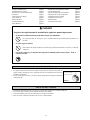
Acson IM-5ACV3-0505-ACSON Guida d'installazione
- Tipo
- Guida d'installazione

AIR COOLED CHILLER
(R410A INVERTER SERIES)
IM-5ACV3-0505-ACSON
Part No.: R08019025193
MINI CHILLER
INSTALLATION MANUAL

i
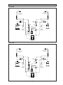
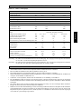
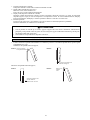
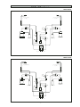
OUTLINE AND DIMENSIONS
5ACV 100/135 CR
Model A B C D E
FG
Base Leg Hole
5ACV 100 CR 1500 900 1245 1190 297.5 307.5 1446
5ACV 135 CR 1800 1150 1245 1190 347.5 416 1766
HIJKLM
100 265 385 60 200 170
100 265 385 60 200 170
1192.2
98.7
256.0
174.0
504.5
128.0
624.5
38.0
70.0
1199.2
1992.5
50.0
50.0
30.0
100.0
1786.3
1683.3
2092.5
1998.4
WATER INLET
WATER OUTLET
SEE DETAIL A
DETAIL A
A
C
D
LL
G
K
M
I
J
B
WATER OUTLET
WATER INLET
H
FE
5ACV 210 CR

ii
5ACV 100/135 CR
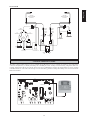
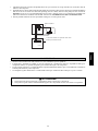
UNIT INSTALLATION
700
500 500
1100
5ACV 210 CR
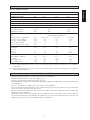
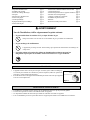
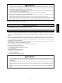
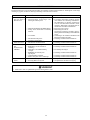
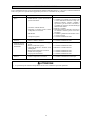
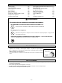
! Осторожно
Острые края и поверхности змеевиков являются
потенциальными местами нанесения травм. Остерегайтесь
контакта с этими местами.
! Cuidado
Los Bordes afilados y la superficie del serpentín pueden producir lesiones.
Evite tocarlos.
! Cautela
Per preservarsi da eventuali ferite, evitare di toccare gli spigoli affilali e la
superficie della serpentina.
! Vorsicht
Scharfe Kanten und Wärmetauscherflächen stellen eine Gefahrenquelle dar.
Jeglicher Kontakt mit diesen Stellen ist zu vermeiden.
! Avertissement
Les bords coupants et les surfaces du refroidisseur tuulaire présentent
un risque de blessure. Mieux vaut éviter le contact avec ces endroits.
! Caution
Sharp edges and coil surfaces are potential locations which may cause
injury hazards. Avoid from being in contact with these places.

iii
!!
!!
! CAUTION
• Improper handling of unit during installation could result in leaks, electrical shock or unit malfunction.
• Contact your dealer for reinstallation or dismantling of unit.
• Do not introduce foreign objects such as fingers, sticks etc. into the air inlet and air outlet.
• Do not climb or place objects on top of mini chiller.
!!
!!
! AVERTISSEMENT
• De mauvaises manoeuvres lors de l’installation peuvent entraîner des fuites, des chocs électriques ou des disfonctionnements
de l’appareil.
• Contacter le distributeur pour la réinstallation ou le démontage de l’appareil.
• Ne pas introduire d’objets étrangers comme les doigts, des petits bâtons, etc., dans l’ouverture d’entrée et de sortie d’air.
• Ne pas grimper ou déposer des objets sur le dessus du mini-refroidisseur.
!!
!!
! VORSICHT
• Unsachgemäße Handhabung des Geräts bei der Installation kann zu Lecks, Stromschlägen und Fehlfunktionen beim
Gerät führen.
• Wenden Sie sich für die Wiederinstallation oder fürs Abmontieren des Geräts an Ihren Händler.
• Führen Sie keine Fremdkörper wie Finger, Stäbe etc. in die Lufteintritts- bzw. Luftaustrittsöffnung ein.
• Steigen Sie nicht auf das Mini-Kühlgerät und stellen Sie keinerlei Objekte auf das Gerät.
!!
!!
! ATTENZIONE
• Una movimentazione impropria dell’unità durante l’installazione può provocare perdite, elettroshock o un
malfunzionamento dell’apparecchio.
• Contattare il proprio fornitore per una reinstallazione o smontaggio dell’apparecchio.
• Non introdurre oggetti estranei, come dita, bastoncini, ecc., nell’entrata e nello scarico dell’aria.
• Non salire e non porre oggetti nella parte superiore dell’unità.
!!
!!
! CUIDADO
• El manejo incorrecto de la unidad podría tener como resultado escapes, un funcionamiento defectuoso o descargas eléctricas.
• Solicite a su distribuidor la instalación, reinstalación o desmontaje de la unidad.
• No introduzca objetos extraños tales como los dedos, palos, etc. en las tomas y salidas de aire.
• No coloque objetos sobre la unidad ni se suba a ella.
!!
!!
! ОСТОРОЖНО
• Неправильное обращение с аппаратом во время установки может стать причиной протеканий,
поражения электрическим током или неправильной работы аппарата.
• Если необходимо переустановить или демонтировать аппарат, обращайтесь к своему дилеру.
• Не вставляйте в воздухозаборные и воздуховыпускные отверстия посторонних предметов, таких как
пальцы, палки и т.п.
• Не взбирайтесь на аппарат и не ставьте на него никаких предметов.

iv
This product is subjected to Waste of Electrical and Electronic Equipment Regulations (WEE
E
Regulations). The waste product shall be separately collected by specific collection and treatment centre
.
P
lease refer to local authorithy for these centres. This is only applicable to European Union countries
.
Ce produit est soumis
à
la r
à
é
r
r
é
chets
d
es
é
é
lectriques e
t
é
lectroniques (r
é
r
r
é
chet doi
t
ê
tre collect
é
t
s
é
par
é
r
r
m
ent par un centre de collect
e
et de traitement s
p
é
cifique. Veuillez vous r
é
r
r
f
é
f
f
é
s locales pour conna
î
a
tre ces centres. Ceci
îî
é
enne
.
Questo prodotto
è
soggetto alle disposizioni RAEE (Rifiuti di apparecchiature elettriche ed elettroniche)
.
à
ritirato da un centro incaricato del ritiro e smaltimento. Per conoscere il
à
n
ome del centro pertinente, contattare le autori
t
à
locali. Questa disposizione
à
è
valida solamente i paes
i
d
el
l
’
U.
E
.
é
ctrico y Electr
ó
n
ico en materia d
e
ñ
ñ
ado ser
á
í
fico
í
í
de colecc
i
ó
í
ó
n
Europea
.
Dieses Produkt unterliegt den Bestimmungen zur Entsorgung von elektrischen und elektronische
n
G
er
ä
ä
ä
tes
ää
getrennt vom Hausm
ü
ll bei Ihrer
ö
r
tlichen
M
ü
ö
ä
ndiges Abfall-Amt. Dieser
ää
Hinweis gilt nur f
ü
f
f
rL
ä
nder der Europ
ää
ä
ischen Union
.
П
р
оцес
с
у
тилизаци
и
д
анног
о
прод
у
кт
а
рег
у
лир
у
етс
я
п
р
авилам
и
п
о
у
тилизаци
и
отхо
д
о
в
и
(WEEE Re
g
ulations).
и
об
р
аботк
е
.
,
.
Э
т
и
п
р
авил
а
Ев
р
опейског
о
.
NOTICE
ENGLISH
Important information regarding the refrigerant used
This product contains fluorinated greenhouse gases covered by the Kyoto
Protocol. Do not vent gases into the atmosphere.
Refrigerant type: R410A R407C
GWP
(1)
value: 1975 1652.5
: hermetically sealed system
(1)
GWP = global warming potential
The refrigerant quantity is indicated on the unit name plate.
Periodical inspections for refrigerant leaks may be required depending on
European or local legislation. Please contact your local dealer for more
information.
DEUTSCH
Wichtige Informationen hinsichtlich des verwendeten Kältemittels
Dieses Produkt enthält fluorierte Treibhausgase, die durch das Kyoto-Protokoll
abgedeckt werden. Lassen Sie Gase nicht in die Atmosphäre ab.
Kältemitteltyp: R410A R407C
GWP
(1)
Wert: 1975 1652,5
: hermetisch verschlossenes System
(1)
GWP = Treibhauspotential
Die Kältemittelmenge ist am Typenschild der Einheit angegeben.
Überprüfungen in Bezug auf Kältemittellecks müssen in regelmäßigen
Abständen je nach den europäischen oder nationalen Bestimmungen
durchgeführt werden. Kontaktieren Sie bitte Ihren örtlichen Händler bezüglich
weiterer Informationen.
FRANÇAIS
Information importante relative au réfrigérant utilisé
Ce produit contient des gaz fluorés à effet de serre encadrés par le protocole
de Kyoto. Ne pas laisser les gaz s'échapper dans l'atmosphère.
Type de réfrigérant: R410A R407C
Valeur GWP
(1)
: 1975 1652,5
: système hermétique
(1)
GWP = potentiel de réchauffement global
La quantité de réfrigérant est indiquée sur la plaquette signalétique
de l'unité.
Des inspections périodiques de fuites de réfrigérant peuvent être exigées en
fonction de la législation européenne ou locale. Veuillez contacter votre
distributeur local pour plus d'informations.
ESPAÑOL
Información importante en relación al refrigerante utilizado
Este producto contiene los gases invernaderos fluorados regulados por el
Protocolo de Kioto. No vierta gases a la atmósfera.
Tipo de refrigerante: R410A R407C
GWP
(1)
Valor: 1975 1652,5
: sistema sellado herméticamente
(1)
GWP = global warming potential (potencial de calentamiento global)
La cantidad de refrigerante está indicada en la placa de especificaciones
técnicas de la unidad.
Puede ser necesario realizar inspecciones periódicas para localizar fugas de
refrigerante, dependiendo de la legislación europea o local vigente. Contacte,
por favor, con su distribuidor local para obtener más información.
ITALIANO
Informazioni importanti sul refrigerante utilizzato
Questo prodotto contiene gas fluorinati inclusi nel protocollo di Kyoto. Non
liberare tali gas nell'atmosfera.
Tipo di refrigerante: R410A R407C
Valore GWP
(1)
: 1975 1652,5
: sistema ermeticamente chiuso
(1)
GWP = potenziale di riscaldamento globale
La quantità di refrigerante è indicata nella targhetta con il nome dell'unità.
È possibile che siano necessarie ispezioni periodiche per controllare e entuali
perdite di refrigerante secondo le normative locali e/o europee. Per informazioni
più dettagliate, contattare il rivenditore locale.
Русский
Важная информация об используемом хладагенте
Данное изделие содержит фторированные парниковые газы, на которые
распространяется действие Киотского Протокола. Не выпускайте газы в атмосферу.
Марка хладагента: R410A R407C
Величина ПГП
(1)
: 1975 1652,5
: герметизированная система
ПГП
(1)
= потенциал глобального потепления
Количество хладагента указано в паспортной табличке блока.
В соответствии с общеевропейским или местным законо- дательством
может быть необходима периодическая проверка на наличие утечек
хладагента. За более подробной информа- цией обращайтесь к своему
местному дилеру.
IMPORTANT

v
ELECTRICAL WIRING DIAGRAM
WITH ISOLATOR SWITCH / AVEC INTERRUPTEUR ISOLANT / MIT SCHWINGUNGSISOLATOR /
CON SEZIONATORE MAGNETOTERMICO / CON INTERRUPTOR AISLANTE / С РАЗЪЕДИНИТЕЛЕМ
MODEL : 5ACV 100/135 CR
PART NO : 50 13 9 024972
415V/3PH/50Hz
L1
L2 L3 N
PE
TB1
ISOLATOR
SWITCH
RED
WHITE
BLACK
BLUE
RSTN
A
B
C
G
A'
B'
C'
A
B
C
G
N
A'
B'
C'
N'
FTR1
(50A)
FTR
(25A)
L1 L2 L3 21
T1 T2 T3 22
RED
WHITE
BLACK
YELLOW/GREEN
YELLOW/GREEN
CP1
A2
A1
CP2
A2
A1
L1 L2 L3 21
T1 T2 T3
22
RED
WHITE
BLACK
PE
PE
U
V
W
U
V
W
CP2CP1
TB4
TB5
RED
WHITE
BLACK
YELLOW/GREEN
U
V
W
PUMP
TB2
L1 L2 L3
FR
T1 T2
T3
A2
A1
96
95
98
97
T
R
S
BR-3P
+
-
PFC
12
L1 L2 L3
T1 T2 T3
A2
A1
BR-1P
+
LA LB
L
RD BL OR BL BR BL
H/C H/C
ON/OFF ON/OFF ALARMALARM
HEAT/COOL ON/OFF ALARM
FSC1 FSC2
TB3
FM2 FM1
CF2
25uF
CF1
25uF
1
2
1
2
4WV1 4WV2
BP-H
AU-H
F-2-1 F-2-2 N F-1-2 F-1-1 4WV1 N 4WV2 N
N
NBP-H CC-H3 CC-H2 CC-H1 BOIL AU-H
CAPACITOR BOARD
POWER
BOARD
DC2-
DC1-
DC-
JP-DC
DC2+
DC1+
DC+
EV1
EV2
LCD
DISPLAY
YELLOW/GREEN
RED
WHITE
BLACK
PE
U
V
W
CP
DC-IN
JP-POWER
DC-OUT
PE
FU
PWM1
IPM BOARD
IPM 028404R
POWER 1
UV W
N
P
C
4WV1
4WV2
BP-H
JDC
AU-H
PUMP
BOILER
CC-H1
CP1
CP2
R-PHASE
PHASE
FAN-2-2
R-PHASE
FAN-1-2
FAN-1-1
FAN-2-1
J-RST
N
R
S
T
PE
1-EV1
2-EV2
JK8
SW1
1
8
BL BR BL OR BL RD
JP14
CH
ALARM
ON/OFF
JP1
JP13
JP-POWER1
L1 FL2 FL1
<MAIN BOARD>
IC 090103R
JK2 JK1 JK4
J
K3
JK7
JP8 JP2
JP4
JP5
JP7
JP6
JP3
J
P1
7
JP18
JP19
JP20
JP11
JP9
LP2 HP1 FLW
HP2
LP1
TOC1
TOC4
TCO3
TCD1
TCD3
TOC2
TBP
E
-1
TBP
L-
1
TOA
TCS1
TCD1
TCS2
TWL
TWE
TBPL-2
TBPE-2

vi
WITH ISOLATOR SWITCH / AVEC INTERRUPTEUR ISOLANT / MIT SCHWINGUNGSISOLATOR /
CON SEZIONATORE MAGNETOTERMICO / CON INTERRUPTOR AISLANTE / С РАЗЪЕДИНИТЕЛЕМ
MODEL : 5ACV 210CR
PART NO : 50 13 4 085020
ISOLATOR
SWITCH
L1
L2 L3
N
380~415V / 3PH / 50Hz
R
ST
N
A
B
C
G
N
A’
B’
C’
FTR1
(50A)
A
B
C
G
N
A’
B’
C’
N’
FTR2
(25A)
COMP 1 COMP 2
PUMP
U
V
W
U
V
W
U
V
W
TB4 TB5
RED
WHITE
BLACK
GREEN/YELLOW
RED
WHITE
BLACK
GREEN/YELLOW
RED
WHITE
BLACK
GREEN/YELLOW
L1 L2 L3
T1 T2 T3
21
22
A1
A2
L1 L2 L3
T1 T2 T3
21
22
A1
A2
CP1
CP2
L1 L2 L3
T1 T2 T3
A1
A2
95
96
97
98
PUMP
TB2
H/C H/C
ON/OFF ON/OFF ALARM ALARM
RD BL BR
OR BL
BL
HEAT/COOL ON/OFF ALARM
FSC1
FSC2
TB3
FAN-2-1 FAN-2-2 N FAN-1-2 FAN-1-1 4WV1 N 4WV2 BP_H N CC_H3 CC_H2 N CC_H1 BOIL N AU_H
AU_H
4WV24WV1
BP_H
FM1FM2
CF2
18uF
CF1
18uF
COMP
LCD
DISPLAY
PANEL
EV1 EV2
BR-3P
T
S
R
+
-
PFC
12
1
2
EST
L1 L2 L3
T1
T2
T3
A1
A2
FAN-2-1
FAN-2-2
FAN-1-2
FAN-1-1
4WV1
4WV2
BP_H
JP13
CC_H1
BOILER
AU_H
R_PHASE
PHASE
JDC
PUMP
CP1
CP2
R_PHASE
EV 2
EV 1
RDBLBR ORBL BL
JP1
JP14
JK8
J-RST
JP_POWER1
L1 FL2 FL1
JP3
PE
T
S
R
N
JK2 JK1 JK4 JK3 JK7 JP8 JP2 JP4 JP5 JP7 JP6 JP17 JP18 JP19 JP20 JP11 JP9
LP2 HP1 FLW HP2 LP1
TOC1
TOC4
TOC3
TCD1
TCD3
TOC2
TBPE-1
TBPL-1
TOA
TCS1
TCD2
TCS2
TWL
TWE
TBPL-2
TBPE-2
BR-1P
-
+
LA LB
L
PWM1
MAIN BOARD
IC090102
U
V
W
RED
WHITE
BLACK
GREEN/YELLOW
UV
W
N
P
POWER1
IPM BOARD
0.47uF
C
FUSE
JP_POWER
DC_OUT
PE
DC_IN
POWER
BOARD
CAPACITOR BOARD
DC2 -
DC1 -
DC -
DC2 +
DC1 +
DC+
JP_DC
GROUND PLATE
CH
ALARM
ON/OFF
SW1
18
ON

English
This manual provides the procedures of installation to ensure a safe and good standard of operation for the
chiller.
Special adjustments may be necessary to suit local requirements.
Before using the chiller, please read this instruction manual carefully and keep it for future reference.
INSTALLATION MANUAL
AIR COOLED INVERTER CHILLER
MODEL
Part No.: R08019024894
IM-5ACV3-0505-McQuay
!!
!!
!
WARNING
• Installation and maintenance should be performed by qualified persons who are familiar with local code and
regulation, and experienced with this type of appliance.
HEAT PUMP
R410A
5ACV100CR / M5ACV100CR
5ACV135CR / M5ACV135CR
5ACV210CR / M5ACV210CR

1-1
!!
!!
!
CAUTION
Please take note of the following important points when installing.
• Do not install the unit where leakage of flammable gas may occur.
If gas leaks and accumulates around the unit, it may cause fire ignition.
• Do not overcharge the unit.
This unit is factory pre-charged. Overcharge will cause over-current or damage to the compressor.
• Sharp edges and aluminium fin coil surface are potential location which may cause injury
hazards. Avoid from being in contact with these locations.
INDEX
- Outline And Dimensions page i
- Unit Installation page ii
- Electrical Wiring Diagram page v
- Transportation page 1
- Installation Location page 1
- Physical Data page 2
- Water Piping and Fitting page 2
- Electrical And Wiring page 3
- Electrical Data page 3
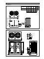
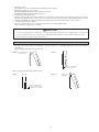
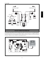
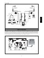
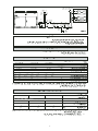
TRANSPORTATION
• The unit should be lifted using a crane. Ensure that the hanger belts are not touching panel
and the coil, top front panel (use protective panel) as shown in Figure 1.
• The bolt of the base and channel support can be removed after putting the unit on the fixed
location.
Hanger
Hanging Belt
Protective Panel
INSTALLATION LOCATION
• Installation work should be done by the authorized dealer or qualified contractor.
• Make sure there is sufficient airflow around the unit.
• Vibration isolator should be provided to prevent vibration and noise from the unit.
• There should be sufficient space allocated for servicing and maintenance.
Figure 1
- Recommended Fuse And Cable Sizes page 3
- Refrigerant Circuit page 4
-
Special Precautions When Dealing With R410A Unit
page 4
- Refrigerant Circuit Diagrams page 5
- Control Operation Guide page 6
- LCD Panel Installation page 7
- Maintenance page 8
- Troubleshooting page 9

1-2
English
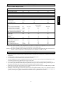
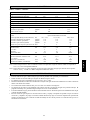
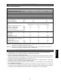
PHYSICAL DATA
Table A-1 : R410A - Heat Pump
Model 5ACV100CR 5ACV135CR 5ACV210CR
Nominal cooling capacity kW 27.84 38.54 58.56
Nominal heating capacity kW 29.31 41.47 61.49
Operating weight kg 405.0 525.0 682.0
Refrigerant charge R410A kg 4.7 × 2 6.0 × 2 9.5 / 8.5
Compressor 1 Scroll + 1 Inverter Compressor 2 Scoll + 1 Inverter Compressor
Control system LCD Electronic Control
Refrigerant - water heat exchanger Brazed Plate Heat Exchanger
Water connections (BSP) inches 1 1/4 1 1/2
Maximum water pressure kPa 1000 1000
Hydronic circuit
Pump Horizontal Multistage End-Suction
Available pressure (Cooling/Heating) kPa 127.7 / 157.3 167.4 / 157.6 258.5 / 244.0
Water inlet connection (BSPT) inches 1 1/4 1 1/4 1 1/2
Water outlet connection (BSPT) inches 1 1/4 1 1/4 1 1/2
Drain tap coupling (BSPT) inches 1/2 1/2 1/2
Closed expansion tank water volume litre 8 8 8
Refrigerant - air heat exchanger
Tube diameter mm 9.52 9.52 9.52
No. of rows 2 2 2
Tubes/row 42 42 62
Fin spacing mm
1.59 1.59 0.6299
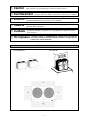
Fan
Diameter/Number of O/D fan mm 24 x 2 26 x 2 32 x 2
No. of blades 4 4 6
Air flow (high speed) m
3
/hr 6480 14400 11890
Fan speed (high speed) r/min 690 780 550
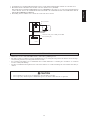
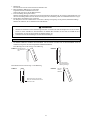
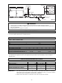
WATER PIPING AND FITTING
• All water pipe must be insulated to prevent capacity losses and condensation.
• Install a 40-60 mesh strainer to ensure water quality is good.
• Water pipe recommended are black steel pipe and copper pipe.
• During installation, the piping of the unit should be clamp before rotating the installation pipe to reduce the moment induce
on the unit piping.
• Users are recommended to install the pipe and accessories as shown in Figure 2.
• An air vent must be installed at the highest position, while a drainage plug at the lowest position of the water circuit. Open
the air vent to release any air trap in the water circuit.
• Run the clean water through the water inlet and operate the pump to drain out the dirty water. Clean the strainer after
running the pump for 30 minutes.
• Fill up the water circuit after connecting all the pipes and equipment. Check water leakages at all connections and joints.
Do not start the unit when the system is leaking. To optimize the capacity of the system, ensure that the system is free of air
bubbles. The air trapped in the system would make the system unbalanced.
Note: For cooling nominal values are based on 12°C / 7°C entering / leaving evaporator water temperature, 35°C air ambient
temperature.
Note: For heating nominal values are based on 40°C / 45°C entering / leaving evaporator water temperature, 7°C DB / 6°C
WB air ambient temperature.

1-3
!!
!!
! CAUTION
• Do not allow water remain in the water pipes if the unit is not operating for a long period.
Water must be drained out if the unit is not running during winter. Failing to do so would cause the pipe to crack.
• Do not drink the chilled water in the unit.
ELECTRICAL AND WIRING
• Refer to the wiring diagram provided on the unit when making electrical wiring.
• Do not ground any electrical equipment to the water piping.
ELECTRICAL DATA
Table B-1 : R410A - Heat Pump
Model 5ACV100CR 5ACV135CR 5ACV210CR
Power supply V-ph-Hz 400 / 3 / 50
Voltage range V 380-415
Nominal Power Input (Cooling/Heating) W 12 / 11.4 15.8 / 16.3 23.2/22.9
Nominal Current Input (Cooling/Heating) A 24.4 / 23.9 30.0 / 31.1 38.5/38.1
System 1* System 2 System 1* System 2 System 1(inv)*System 1System 2
Compressor Maximum Continous Current A 21.0 13.7 21.0 26.0 21.0 17.0 29.0
Compressor Full Load Current (FLA) A 16.4 11.1 18.6 16.6 16.4 10.7 22.2
Compressor Locked Rotor Current (LRA) A – 67 – 111 – 90 118
Pump Power Input (Cooling/Heating) W 1013 / 1026 882 / 907 1175/1294
* Readings taken at rated compressor frequency. The Power Input and Current differ depending on the combination of
outdoor temperature and entering water temperature. For further details, please refer to Technical Manual.
PRESSURE GAUGE
GATE
VALVE
GATE
VALVE
BALANCING
VALVE
THERMOMETER
FLEXIBLE
GATE VALVE
(LOWER POSITION
FOR DRAINAGE)
AIRVENT (INSTALL
HIGHEST POSITION)
FAN COIL UNIT/AIR HANDLING UNIT
GATE
VALVE
Figure 2
THERMOMETER
GATE
VALVE
GATE
VALVE
BALANCING
VALVE
STRAINER
CHECK
VALVE
MAKE UP
VALVE
PRESSURE
DIFFERENTIAL
VALVE
FLEXIBLE
Heat Pump
Model 5ACV 100 CR 5ACV 135 CR 5ACV 210CR
Voltage Range ** 380 – 415V /3Ph /50Hz + N + !
Recommended Fuse * A 40 60 100
Power Supply Cable Size *mm
2
10 10 10
Number of Conductor 55 5
Interconnection Cable Size *mm
2
1.5 1.5 1.5
RECOMMENDED FUSE AND CABLE SIZES
IMPORTANT : * The figures shown in the table are for information purpose only. They should be checked and selected to
comply with the local/national codes of regulations. This is also subject to the type of installation and
conductors used.
** The appropriate voltage range should be checked with label data on the unit.

1-4
English
!!
!!
! CAUTION
• All field wiring must be installed in accordance with the national wiring regulation.
• All the terminals and connections must be tightened. Improper connection and fastenings could cause electric shock,
short circuit and fire.
• Ensure that the rated voltage of the unit corresponds to that of the name plate before commencing wiring work
according to the wiring diagram.
• The unit must be GROUNDED to prevent possible hazards due to insulation failure.
• All electrical wiring must not touch the refrigerant piping, compressor, pump, fan motor or any moving parts of
the fan motors.
• Do not operate the chiller with wet hands. It would result in electric shock.
• Do not use fuse of different amperage than stated. Using wire etc. to replace a fuse could cause equipment damage
or fire.
Electrical Wiring Diagram (please refer to Appendix 3).
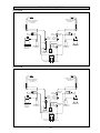
REFRIGERANT CIRCUIT
• All mini chillers units are pre-charged with R410A refrigerant.
SPECIAL PRECAUTIONS WHEN DEALING WITH R410A UNIT
• R410A is a near azeotrope refrigerant blend of hydro fluorocarbon (HFC) which is environmental friendly. It has Zero
Ozone Depletion Potential (ODP=0) and this conforms to Montreal Protocol regulations. It has no flame propagation and
a low toxic refrigerant (rated as A1 by ARI). R410A is a mixture of R32 (50%) and R125 (50%).
• POE oil is used as lubricant for R410A compressor, which is different from the mineral oil used for R22 compressor.
During installation or servicing, extra precaution must be taken not to expose the R410A system too long to moist air.
Residual POE oil in the piping and components can absorb moisture from the air.
• Refrigerant R410A is more easily affected by dust of moisture compared with R22, make sure to temporarily cover the
ends of the tubing prior to installation.
• No additional charge of compressor oil only is permitted.
• No refrigerant other than R410A is permitted.
• Tools designed specifically for R410A only.
i) Manifold gauge and charging hose
ii) Gas leak detector
iii) Refrigerant cylinder/charging cylinder
iv) Vacuum pump c/w adaptor
v) Flare tools
vi) Refrigerant recovery machine
!!
!!
! CAUTION
• R410A must be charged as liquid. Usually R410A cylinder is equipped with a dip-pipe for liquid withdrawal.
If there is no dip-pipe, the cylinder should be inverted so as to withdraw liquid R410A from the valve.
• Do not top-up when servicing leak, as this will reduce the unit performance. Vacuum the unit thoroughly and then
charge the unit with fresh R410A according to the amount recommended in the specification.
• Do not touch the compressor or refrigerant piping when the chiller is running. If necessary wear protective gloves.

1-5
FIN TUBE
HEAT EXCHANGER
(SYSTEM 1)
FIN TUBE
HEAT EXCHANGER
(SYSTEM 2)
4-WAY VALVE
VARIABLE SPEED
COMPRESSOR
COMPRESSOR
SUCTION
ACCUMULATOR
SUCTION
ACCUMULATOR
WATER
OUT
WATER
IN
LIQUID
RECEIVER
LIQUID
RECEIVER
EXV
HEATING
CAP
TUBE
FILTER
DRIER
FILTER
DRIER
COOLING
CAP
TUBE
4-WAY VALVE
CHECK
VALVE
CHECK
VALVE
REFRIGERANT CIRCUIT DIAGRAMS
5ACV 100 CR
FIN TUBE
HEAT EXCHANGER
(SYSTEM 1)
FIN TUBE
HEAT EXCHANGER
(SYSTEM 2)
4-WAY VALVE
VARIABLE SPEED
COMPRESSOR
COMPRESSOR
SUCTION
ACCUMULATOR
SUCTION
ACCUMULATOR
WATER
OUT
WATER
IN
LIQUID
RECEIVER
LIQUID
RECEIVER
EXV
HEATING
CAP
TUBE
FILTER
DRIER
FILTER
DRIER
COOLING
CAP
TUBE
4-WAY VALVE
CHECK
VALVE
CHECK
VALVE
5ACV 135 CR

1-6
English
MAIN BOARD
CC-H1
BOILER
4WV1
4WV2
BP-H
AU-H
PUMP
FAN2
FAN1
R-PHASE
JP-Y
JDC
SW2
SW1
JP6
JP5 JP4 JP3
JP7
JP14
JP10
JP9
JP8 JP2
JP11
JK3 JK7
JK4
JK1 JK2
JP13
The unit is equipped with a microprocessor controller board. The microprocessor controller is provided to give temperature
control for the system by accurately measuring and controlling the water entering and water leaving temperature. The tem-
perature setting in the unit is preset in the factory. It is not recommended to change the setting unless necessary. A wired
controller handset is connected to the microprocessor board. Every parameter setting and reading can be observed from the
LCD of the handset.
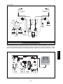
5ACV 210 CR
CONTROL OPERATION GUIDE
FIN TUBE
HEAT EXCHANGER
(SYSTEM 1)
VARIABLE SPEED
COMPRESSOR
COMPRESSOR
SUCTION
ACCUMULATOR
WATER
OUT
LIQUID
RECEIVER
EXV
FILTER
DRIER
CHECK
VALVE
EXV
CHECK
VALVE
COMPRESSOR
4-WAY VALVE
OIL
SEPARATOR
OIL
SEPARATOR
OIL
RETURN
TUBE
TWIN
TUBE JOINT
FILTER
DRIER
WATER
IN
LIQUID
RECEIVER
SUCTION
ACCUMULATOR
4-WAY VALVE
FIN TUBE
HEAT EXCHANGER
(SYSTEM 2)
TWIN
TUBE JOINT
FIN TUBE
HEAT EXCHANGER
(SYSTEM 1)
FIN TUBE
HEAT EXCHANGER
(SYSTEM 2)
4-WAY VALVE
VARIABLE SPEED
COMPRESSOR
COMPRESSOR
SUCTION
ACCUMULATOR
SUCTION
ACCUMULATOR
WATER
OUT
WATER
IN
LIQUID
RECEIVER
LIQUID
RECEIVER
EXV
FILTER
DRIER
FILTER
DRIER
4-WAY VALVE
CHECK
VALVE
CHECK
VALVE
TWIN
TUBE JOINT
OIL
SEPARATOR
OIL
RETURN
TUBE
OIL
SEPARATOR
COMPRESSOR
TWIN
TUBE JOINT
EXV

1-7
!!
!!
! CAUTION
• Use the controller handset to switch on / off the unit. Do not plug off the main power supply directly, it would cause
the unit to breakdown. In case of emergency switch off the isolator switch located on the front panel of the unit.
• Do not change the settings of the safety devices.
1. Handset location
The handset is located on a metal bracket behind the right door panel.
2. LED Display (microprocessor board)
The keypad LED will light up when the unit is powered up.
The LCD will light up when the unit is turned on.
3. LCD display (controller handset)
During normal operations, the LCD can display the entering water temperature, the leaving water temperature, the enter-
ing water setpoint temperature, compressor on or off status and outdoor air temperature. When malfunctioning occurred,
the LCD would blink. The display would show the faulty parameter and the date and time of the occurrence.
4. Controller functioning specification
There is a 3 minute delay for the compressor and fan motor to restart (default setting).
During defrosting, fan motor is not running.
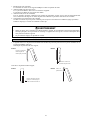
• The unit comes with a LCD panel installed. To change the position or re-install the LCD panel, follow the installation
guide below.
When fastening the LCD panel to the bracket,
Step 1 Step 2
When removing the LCD panel from the bracket,
Step 1 Step 2
Hook the LCD panel
from the top first
Push to fasten the LCD
panel to the bracket
Remove the LCD panel
from the bottom part first
with help of a screw driver
Remove the
LCD panel
LCD PANEL INSTALLATION

1-8
English
MAINTENANCE
• Maintenance service of the mini chiller must be carried out by qualified persons.
• The unit is easily accessible for servicing and maintenance by accessing the front panel of the unit (for electrical compo-
nents) and the panel door (for refrigerant and water circuit).
• For consistent performance it is recommended that a routine maintenance of cleaning the coil surfaces to conducted
because of dusty surroundings.
• It is also recommended that regular checks on the water strainer to be conducted. Change the water strainer if it is dirty or
choked.
!!
!!
! CAUTION
• Do not attempt to do any service or maintenance when the unit is operating.
• Do not spray any chemical agents or flammable agents to the unit. It could cause fire or explosion.
1. A 3V DC battery is supplied with the LCD. It is used to ensure that the LCD displays real time once the timer is set.
2. The LCD is wired to the main board via CN8 connection. (This is factory installed)
If the wiring between the LCD and PCB must be longer, an alternative is used. Use a 4-core wire of the desired length and
connect this wire between the terminal block CN2 on the LCD to the terminal block CN5 on the PCB. Ensure that the
correct wire terminals are connected.
3. Networking between chillers can be carried out. Connect the wire as shown
Factory installed
Alternative wiring between LCD panel and PCB
For networking only
Main Board unit 00
A
A
A
B
B
B
12V
12V
12V
GND
GND
GND
JP13
LCD Panel
CN8
CN2
CN5
PCB unit 01

1-9
TROUBLESHOOTING
When any malfunction is occurred, immediately switch off the power supply to the unit, and contact the local dealer, if
necessary. Some simple troubleshooting tips are given below :
1. Compressor does
not start.
2. Fan does not work.
3. Unit does work,
but insufficient
cooling.
4. Flow Switch Error
SYMPTOMS POSSIBLE CAUSES REMEDIAL ACTION
• No power supply.
• Fuses blown or automatic circuit break-
down open.
• Defective contactor or coil.
• Unit is stopped because safety device has
tripped.
• Loose wires.
• Compressor faulty.
• No power supply.
• Fan motor faulty.
• Thermostat setting too high.
• Condenser coil dirty.
• Obstacle blocking air inlet or outlet of the
unit.
• Insufficient refrigerant in the system.
• Improper water flow rate.
• Water in the system is contaminated.
• No water in the system.
• Low water level in the system.
• Check power supply.
• Look for short circuit or grounded wires in
motor windings. Replace fuses and reset
circuit breakers when the fault has been
corrected. Check tightness and soundness of
all electrical connections.
• Repair or replace.
• Determine the type of safety shut down and
correct the default before the unit is restarted.
• Check wire connections and tighten terminal
screws.
• Contact local dealer.
• Check power supply.
• Contact local dealer.
• Reset thermostat.
• Contact local dealer.
• Remove the obstacle.
• Contact local dealer.
• Contact local dealer.
• Contact local dealer.
• Check water supply.
• Check water supply.
!!
!!
! CAUTION
• Troubleshooting must be performed by qualified personnel.

English
Le présent manuel fournit les procédures d’installation pour assurer le bon fonctionnement et la sécurité du
refroidisseur.
Des ajustements spésifiques peuvent être nécessaires pour se conformer aux réglementations locales.
Avant d’employer le refroidisseur, lisez attentivement ce manuel, et conservez-le pour consultation future.
MANUEL D’INSTALLATION
REFROIDISSEUR CONVERTISSEUR À AIR
MODÈLE
Part No.: R08019024894
IM-5ACV3-0505-McQuay
!!
!!
!
ATTENTION
• L’installation et la maintenance doivent être exécutées par une personne qualifiée qui est familiarisée avec les lois
et réglementations en vigueur, et aussi expérimentée dans ce type d’équipements.
POMPE À CHALEUR
R410A
5ACV100CR / M5ACV100CR
5ACV135CR / M5ACV135CR
5ACV210CR / M5ACV210CR

2-1
!!
!!
!
AVERTISSEMENT
Lors de l’installation, vérifier soigneusement les points suivants.
• Ne pas installer dans des endroits où il y a risque de fuites de gaz.
Danger d’incendie en cas de fuite ou de concentration de gaz à proximité du conditionneur.
• Ne pas surcharger le conditionneur.
L’appareil est pré-chargé en usine. Toute surcharge provoquerait une surintensité et des dommages au
compresseur.
• Les angles pointus et la surface des ailettes en aluminium du condenseur peuvent être
dangeureux et provoquer des accidents. Evitez tout contact avec ce type d’endroits.
SOMMAIRE
- Disposition Et Dimensions page i
- Installation De L’Unité page ii
- Schéma De Câblage Électrique page v
- Transport page 1
- Sélection De L’Emplacement page 1
- Données Physiques page 2
- Circuit Hydraulique page 2
- Equipement Electrique Et Câblage page 3
- Données Électriques page 3
TRANSPORT
• L’appareil doit être soulevé au moyen d’une grue. S’assurer que les câbles de l’élinguage
ne touchent pas la batterie du condenseur le panneau supérieur (utiliser un panneau de
protection), comme indiqué dans la Figure 1.
• Les boulons de la base et de support de la canalisation péuvent être enlevé dès que l’appareil
a été fixé à son emplacement.
Crochet
Elingue
Panneau de Protection
SÉLECTION DE L’EMPLACEMENT
• L’installation de l’appareil doit être effectuée par un distributeur autorisé ou par du personnel qualifié.
• S’assurer de la présence d’un flux d’air suffisant autour de l’appareil.
• Un dispositif d’isolation doit être fourni pour réduire les vibrations et le bruit de l’appareil.
• Lors de l’installation prévoir un espace libre autour de l’appareil pour faciliter l’accessibilité lors de l’entretien.
Figure 1
- Sections Des Cables Et Fusibles De Protection page 3
- Circuit Frigori Fique page 4
-
Précautions Spéciales Pour Les Appareils Au R410A
page 4
- Schémas du circuit frigorifique page 5
- Unité De Contrôle Des Opérations page 6
- Installation du panneau LCD page 7
- Entretien page 8
- Recherche Et Anlyse Des Pannes page 9

2-2
Français
DONNÉES PHYSIQUES
Tableau A-1 : R410A - Pompe à Chaleur
Modèles 5ACV100CR 5ACV135CR 5ACV210CR
Capacité frigorifique nominale kW 27,84 38,54 58,56
Capacité calorifique nominale kW 29,31 41,47 61,49
Poids en fonctionnement kg 405,0 525,0 682,0
Charge de Réfrigérant R410A kg 4,7 × 2 6,0 × 2 9,5 / 8,5
Compresseur 1 Compresseur scroll + 1 Compresseur Convertisseur 2 Compresseur scroll + 1 Compresseur Convertisseur
Système de Contrôle Contrôle électronique LCD
Échangeur de chaleur à eau Échangeur de chaleur á plaque
Raccordement (BSP) pouces 1 1/4 1 1/2
Pression maximale de l’eau kPa 1000 1000
Circuit hydraulique
Pompe Pompe Centrifugale
Moyenne de la pression (Froid/Chauffage) kPa 127,7 / 157,3 167,4 / 157,6 258,5 /244,0
Raccordement à l’entrée de l’eau (BSPT) pouces 1 1/4 1 1/4 1 1/2
Raccordement à la sortie de l’eau (BSPT) pouces 1 1/4 1 1/4 1 1/2
Raccordement de la vanne d’écoulemen (BSPT) pouces 1/2 1/2 1/2
Volume d’eau du réservoir d’expansion fermé litres 8 8 8
Échangeur de chaleur à air
Diamètre du tube mm 9,52 9,52 9,52
Nombre des rangs 2 2 2
Tubes/rangs 42 42 62
Espace entre les ailettes mm
1,59 1,59 0,6299
Ventilateur
Diamètre/Nombre de ventilateurs O/D mm 24 x 2 26 x 2 32 x 2
Nombre de pales d’hélice 4 4 6
Débit d’air (grande vitesse) m
3
/hr 6480 14400 11890
Vitesse du ventilateur (grande vitesse) tours/min 690 780 550
CIRCUIT HYDRAULIQUE
• Toutes les tuyauteries d’eau doivent être isolées afin d’éviter la formation de condensation et de réduire les déperditions
calorifiques.
• Installer un filtre à maille de 1,5 mm afin d’assurer une bonne qualité de l’eau.
• Les conduites d’eau recommandées sont en acier noir et en cuivre.
• Durant l’installation, les tuyaux de l’appareil doivent être fixés avant de raccorder les tuyaux de l’installation pour éviter
de tordre les tuyauteries de l’appareil lors du serrage des raccords.
• Il est recommandé aux utilisateurs de mettre en place les tuyaux et les accessoires comme indiqué dans la Figure 2.
• Une vanne de purge doit être installé à la partie la plus haute, ainsi qu’un vanne de drainage dans la position à la partie la
plus basse du circuit de l’eau. Ouvrir l’évent pour l’évacuation de l’air du circuit de l’eau.
• Faire passer de l’eau propre dans l’entrée d’eau et actionner la pompe pour faire évacuer l’eau souillée. Nettoyer le filtre
après avoir fait fonctionner la pompe pendant 30 minutes.
• Remplir le circuit d’eau après avoir raccordé tous les tuyaux et l’appareil. Vérifier qu’il n’y a pas de fuites sur tous les
raccordements et les assemblages. Ne pas démarrer l’appareil en cas de fuite. Dans le but d’optimiser la capacité du
système, s’assurer qu’il n’y ait pas de bulles d’air. Et aussi afin déviter le phénomène de cavitation.
Remarque: Les valeurs nominales pour la réfrigération sont calculées en fonction de la température de l’eau, entre 12 et 7°C
à l’entrée / sortie de l’évaporateur, et de la température de l’air ambiant 35°C.
Remarque: Les valeurs nominales pour le chauffage sont calculées en fonction de la température de l’eau, entre 40 et 45°C à
l’entrée / sortie de l’évaporateur, et de la température de l’air ambiant a 7°C DB / 6°C WB
La pagina si sta caricando...
La pagina si sta caricando...
La pagina si sta caricando...
La pagina si sta caricando...
La pagina si sta caricando...
La pagina si sta caricando...
La pagina si sta caricando...
La pagina si sta caricando...
La pagina si sta caricando...
La pagina si sta caricando...
La pagina si sta caricando...
La pagina si sta caricando...
La pagina si sta caricando...
La pagina si sta caricando...
La pagina si sta caricando...
La pagina si sta caricando...
La pagina si sta caricando...
La pagina si sta caricando...
La pagina si sta caricando...
La pagina si sta caricando...
La pagina si sta caricando...
La pagina si sta caricando...
La pagina si sta caricando...
La pagina si sta caricando...
La pagina si sta caricando...
La pagina si sta caricando...
La pagina si sta caricando...
La pagina si sta caricando...
La pagina si sta caricando...
La pagina si sta caricando...
La pagina si sta caricando...
La pagina si sta caricando...
La pagina si sta caricando...
La pagina si sta caricando...
La pagina si sta caricando...
La pagina si sta caricando...
La pagina si sta caricando...
La pagina si sta caricando...
La pagina si sta caricando...
La pagina si sta caricando...
La pagina si sta caricando...
La pagina si sta caricando...
La pagina si sta caricando...
La pagina si sta caricando...
La pagina si sta caricando...
La pagina si sta caricando...
La pagina si sta caricando...
La pagina si sta caricando...
La pagina si sta caricando...
La pagina si sta caricando...
La pagina si sta caricando...
La pagina si sta caricando...
La pagina si sta caricando...
La pagina si sta caricando...
La pagina si sta caricando...
La pagina si sta caricando...
La pagina si sta caricando...
La pagina si sta caricando...
La pagina si sta caricando...
La pagina si sta caricando...
La pagina si sta caricando...
La pagina si sta caricando...
La pagina si sta caricando...
La pagina si sta caricando...
-
 1
1
-
 2
2
-
 3
3
-
 4
4
-
 5
5
-
 6
6
-
 7
7
-
 8
8
-
 9
9
-
 10
10
-
 11
11
-
 12
12
-
 13
13
-
 14
14
-
 15
15
-
 16
16
-
 17
17
-
 18
18
-
 19
19
-
 20
20
-
 21
21
-
 22
22
-
 23
23
-
 24
24
-
 25
25
-
 26
26
-
 27
27
-
 28
28
-
 29
29
-
 30
30
-
 31
31
-
 32
32
-
 33
33
-
 34
34
-
 35
35
-
 36
36
-
 37
37
-
 38
38
-
 39
39
-
 40
40
-
 41
41
-
 42
42
-
 43
43
-
 44
44
-
 45
45
-
 46
46
-
 47
47
-
 48
48
-
 49
49
-
 50
50
-
 51
51
-
 52
52
-
 53
53
-
 54
54
-
 55
55
-
 56
56
-
 57
57
-
 58
58
-
 59
59
-
 60
60
-
 61
61
-
 62
62
-
 63
63
-
 64
64
-
 65
65
-
 66
66
-
 67
67
-
 68
68
-
 69
69
-
 70
70
-
 71
71
-
 72
72
-
 73
73
-
 74
74
-
 75
75
-
 76
76
-
 77
77
-
 78
78
-
 79
79
-
 80
80
-
 81
81
-
 82
82
-
 83
83
-
 84
84


Acson IM-5ACV3-0505-ACSON Guida d'installazione
- Tipo
- Guida d'installazione
in altre lingue
Documenti correlati
Altri documenti
-
McQuay 5ACV 55 CR Guida d'installazione
-
Hitachi HRNM/FSN(2)(M)(E) Istruzioni per l'uso
-
-
Pfannenberg EB 260 Series Quick Instruction
-
Hitachi RAS-8HNPE Istruzioni per l'uso
-
CIAT AQUACIAT 2 ILDH Series Manuale utente
-
-
-
Haier 1U60IS1ERA Guida d'installazione
-
Olimpia Splendid Sherpa AQUADUE OS-CETNH48EI Manuale del proprietario