ROBLIN Vista Manuale del proprietario
- Categoria
- Cappe da cucina
- Tipo
- Manuale del proprietario
Questo manuale è adatto anche per

NOTICE D’INSTALLATION ET D’UTILISATION
INSTRUCTIONS FOR INSTALLATION AND DIRECTIONS FOR USE
MONTAGE- UND GEBRAUCHSANWEISUNG
LIBRETTO DI ISTRUZIONI
INSTRUCCIONES DE INSTALACION E UTILIZACION
MONTAGE- EN GEBRUIKSHANDLEIDING
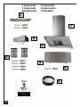
VISTA Murale

F SOMMAIRE
RACCORDEMENT ÉLECTRIQUE
CONSEILS D’INSTALLATIONS
POSE DE L’APPAREIL
FONCTIONNEMENT
CONSEILS D’UTILISATIONS
ENTRETIEN
GARANTIE ET SERVICE APRÈS-VENTE
REMARQUES
D INHALT
NETZANSCHLUSS
MONTAGEHILFEN
MONTAGE DES GERÄTES
BETRIEB DES GERÄTES
NUTZUNG
WARTUNG UND REINIGUNG
GARANTIE UND KUNDENDIENST
WICHTIGE HINVEISE
E SUMARIO
CONEXION ELECTRICA
CONSEJOS DE INSTALACION
INSTALACION DEL APARATO
FUNCIONAMIENTO
CONSEJOS DE UTILIZACION
MANTENIMIENTO
GARANTIA Y ASSISTENCIA TECNICA
NOTA
GB CONTENTS
ELECTRICAL WIRING
INSTALLATION ADVICE
FITTING THE APPLIANCE
OPERATION
USEFUL HINTS
MAINTENANCE
GUARANTEE AND AFTER-SALES-SERVICES
REMARKS
I CONTENUTI
COLLEGAMENTO ELETTRICO
CONSIGLI DI INSTALLAZIONE
POSA DELL’ APPARECCHIO
FUNZIONAMENTO
CONSICLI DI UTILIZZO
MANUTENZIONE
GARANZIA ED ASSISTENZA TECNICA
NOTE
NL INHOUD
ELECTRISCHE BEDRADING
MONTAGE AANWIJZING
AANSLUITEN VAN HET APPARAAT
FUNKTIONEREN
GEBRUIKSADVIES
ONDERHOUD
AFTER SALES SERVICE
OPMERKINGEN

1
F
Nous vous remercions de la conance que vous nous avez accordée en choisissant un appareil de la
gamme ROBLIN.
Celui-ci a fait l’objet de toute notre attention dans sa conception et sa réalisation.
An qu’il vous donne entière satisfaction, nous vous recommandons de lire avec attention cette notice
qui vous expliquera comment l’installer, l’utiliser et l’entretenir dans les meilleures conditions.
La présente notice d’emploi vaut pour plusieurs versions de l’appareil. Elle peut contenir des descriptions
d’accessores ne gurant pas dans votre appareil.
1 RACCORDEMENT ÉLECTRIQUE.
• La hotte est équipée d’un cordon d’alimentation de type HO5VVF 3 x 0,75 mm² comportant une
che normalisée 10/16 A avec système de mise à la terre.
Mode de protection : classe 1. Tension d’alimentation : 220-240 V mono - 50/60Hz.
Vérier que la tension du secteur est identique aux valeurs indiquées sur la plaque signalétique à l’inté-
rieur de la hotte
• Si la hotte est raccordée directement sur le réseau sans sa che, un interrupteur omnipolaire avec
une ouverture de contact de 3 mm doit être installé avant la hotte. Le l de terre (Jaune / vert) ne doit pas
être interrompu par cet interrupteur.
2 CONSEILS D’INSTALLATION.
• Pour un fonctionnement idéal, nous vous conseillons une plage de hauteur de pose qui se situe de
0,65 m à 0,70 m au-dessus du plan de cuisson. Toutefois, il est formellement interdit d’installer toute
hotte ou groupe d’aspiration à une distance inférieure à 0,65 m du plan de travail (risque d’inammation
des ltres). La fumée doit monter naturellement vers la zone de captation.
• Respecter le diamètre de sortie de l’appareil : la hotte ne doit en aucun cas être raccordée à un
conduit de ventilation mécanique contrôlée (V.M.C.).
• Lorsqu’on évacue l’air vicié dans un conduit d’évacuation, veiller à ce que celui-ci ne soit pas déjà
exploité à véhiculer des gaz ou fumées provenant d’appareils alimentés par une énergie autre qu’électri-
que.
• Positionner le plan de cuisson au plus près de l’évacuation et éviter la formation de coudes sur la
gaine, an de réduire au maximum les pertes de charges.
• Dans tous les cas d’installation, veiller au bon renouvellement d’air de la cuisine. Penser à effectuer
une ou des entrées d’air par une grille de section égale ou supérieure au diamètre du tuyau
d’évacuation, an de ne pas mettre la cuisine en dépression.
• Prévoir une aération sufsante lorsqu’un appareil de cuisson ou autre utilise simultanément l’air
ambiant de la pièce où est installée la hotte.
• La dépression maximum crée dans la pièce doit être inférieure à 0.04 mbar, ce qui évite un retour de
gaz de combustion.
• L’appareil doit être positionné de telle façon que la che d’alimentation soit accessible.
• Cet appareil ne doit pas être utilisé par des personnes (y compris les enfants) ayant des capacités psy-
chiques, sensorielles ou mentales réduites, ni par des personnes n’ayant pas l’expérience et la connais-
sance de ce type d’appareils, à moins d’être sous le contrôle et la formation de personnes responsables
de leur sécurité.
Les enfants doivent être surveillés pour s’assurer qu’ils ne jouent pas avec l’appareil.
3 POSE DE L’APPAREIL.
Montage et raccordement doivent être réalisés par un installateur* qualié.
(*) Le non-respect de cette condition entraîne la suppression de la garantie du constructeur et
tout recours en cas d’accident.
Attention: prendre bien soin d’employer les chevilles adaptées au support, se renseigner au près
des fabricants, effectuer un scellement si nécessaire. La société décline toute responsabilité en

2
F
cas d’accrochage défectueux dû au perçage et chevillage.
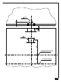
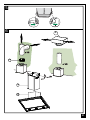
1) Tracer sur la paroi une verticale jusqu’au plafond à l’emplacement de la hotte au centre de la zone
prévue pour le montage de la hotte (Fig.1, rep. 1). Cette ligne sert pour aligner verticalement les diffé-
rentes parties.
2) Positionner le support de conduit ( Rep. 2), centré sur la verticale à 1 à 2 mm du plafond ou de la
limite supérieure et marquer sur la paroi les deux alésages du support. Effectuer sur la paroi deux trous
avec un foret Ø 8 mm. Fixer le support de conduit (Rep. 2) à l’aide des vis 4.5 x 50 et des chevilles
fournies.
3) Dénir le bas de la hotte (Rep 3) an de xer les supports au mur (Fig 3, Rep 4).
Marquer un point sur la ligne verticale à une distance du plan de cuisson de :
d = 1070 min (mesure sans crédence).
d = hauteur crédence (400 mm) + 670 mm (mesure avec crédence).
La hauteur H est la hauteur minimum en mm du plan de cuisson au bas de la hotte (Rep. 3).
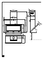
Crédence (Option) : La hauteur de la hotte par rapport au plan de cuisson est déterminée, dans ce
cas par la hauteur de la crédence Rep B et par l’éventuel dosseret du plan de travail. La crédence doit
être montée avant le corps de la hotte et si l’on désire la xer contre le mur tant en haut qu’en bas, il est
nécessaire de la positionner à la juste hauteur. Etant donné qu’il s’agit d’une opération compliquée, elle
doit être effectuée exclusivement par l’installateur de la cuisine ou par du personnel compétent connais-
sant toutes les dimensions nales des meubles.
Effectuer sur la paroi 4 trous avec un foret Ø 8 mm. Fixer les support (Rep. 4) à l’aide des vis 4.5 x 45
et des chevilles fournies.
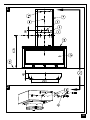
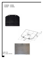
4) Montage du corps de la hotte :
Accrocher le corps (Rep 5) sur les supports muraux.
Parfaire le réglage d’alignement de l’ensemble, à l’aide des vis TH 5 x 25 des supports, ainsi que l’incli-
naison à l’aide des 2 vis 5 x 25 mm TC.
Après avoir effectué tous les réglages d’alignement de l’ensemble de la hotte, verrouiller celle-ci par une
vis de xation positive (Rep 8), an de garantir la sécurité d’accrochage.
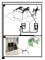
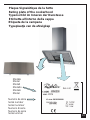
5) Raccordement:
• Pour la version Evacuation Extérieure :
a- Mettre en place le clapet anti-retour (Rep. 8) sur la sortie de l'appareil (Rep. 6), puis le telescopique
et raccorder le tuyau exible (Fig. 6) à l’évacuation extérieure et la sortie de l’appareil . Fixer l’ensemble
à l’aide de colliers ou de ruban adhésif appropriés.
b- Enlever le ltre à graisse , puis s'assurer que le connecteur du cable d'alimentation soit bien branché
dans la prise du moteur (Fig. 5).Raccorder électriquement la hotte (Voir paragraphe Raccordement
Electrique) et vérier le bon fonctionnement de l’éclairage, du moteur et du changement des vitesses
d’aspiration.
c- Emboîter le haut de conduit dans le bas de conduit télescopique (Fig. 1 - Rep. 7a & b) et xer le haut
de conduit au support Rep. 2 par 2 vis M4 Rep. 12c fournies. Puis coulisser le bas de conduit jusqu’au
bloc moteur.
d- Mettre en place le déecteur (Rep. 9)
• Pour la version Recyclage:
a- Fixer le déecteur Rep. R sur la xation du haut de conduit, le déecteur est xé avec les mêmes vis
que le support de haut de conduit (Fig. 2 - Rep. 2).
b- Installer un tuyau de diamètre approprié (Non fourni) entre la sortie de l’appareil et à l’entrée du
déecteur. Fixer l’ensemble à l’aide de colliers ou de ruban adhésif appropriés.
c- Enlever le ltre à graisse, puis s'assurer que le connecteur du cable d'alimentation soit bien branché
dans la prise du moteur (Fig. 5). Raccorder électriquement la hotte (Voir paragraphe Raccordement
Electrique) et vérier le bon fonctionnement de l’éclairage, du moteur et du changement des vitesses
d’aspiration.
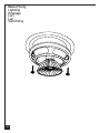
d- Placer la cartouches à charbon actif dans son logement en exerçant une pression sur les languettes
A (Fig. 4).
e- Emboîter le haut de conduit dans le bas de conduit télescopique (Fig. 1 - Rep. 7a & b) et xer le haut
de conduit au support Rep. 2 par 2 vis M4 Rep. 12c fournies. Puis coulisser le bas de conduit jusqu’au
bloc moteur.
f- Mettre en place le déecteurs (Rep. 9)

3
F
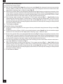
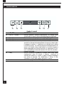
4 FONCTIONNEMENT
T
1
T
2
T3
T
4
T
5
L
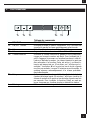
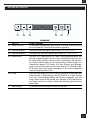
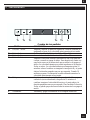
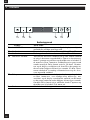
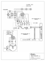
Tableau des commandes
TOUCHE FONCTIONS
T1 ON/OFF Moteur Actionne et arrête le moteur d’aspiration. Sur l’afficheur est
visualisé le pas de la vitesse précédemment sélectionnée.
T2 Vitesse - Réduit la vitesse du moteur: V3 → V2 → V1
T3 Vitesse + Augmente la vitesse du moteur: V1 → V2 → V3
T4 Vitesse intensive Actionne la vitesse intensive en partant d’une vitesse quel-
conque ou lorsque le moteur est éteint. Pour la désactiver, il
suffit d’appuyer à nouveau sur la même touche qui a été uti-
lisée ou d’éteindre le moteur. La vitesse intensive ne peut pas
être actionnée si la fonction Delay est active. La vitesse in-
tensive est temporisée sur 10 minutes: sur l’afficheur est vi-
sualisée l’inscription H et le point en bas à droite clignote
une fois par seconde. Lorsque 10 minutes se sont écoulées, le
système retourne automatiquement à la vitesse précédem-
ment sélectionnée.
T5 Delay Actionne et désactive la modalité d’arrêt total de la hotte
(moteur+éclairage) après 30 minutes: l’afficheur visualise la
vitesse du moteur et le point en bas à droite clignote une fois
par seconde. Pour invalider la fonction Delay on peut ap-
puyer à nouveau sur la même touche ou éteindre le moteur.
L Éclairage Allume et éteint l’éclairage de la hotte.

4
F
5 CONSEILS D’UTILISATION
• Pour obtenir une efcacité maximum d’absorption des fumées ou des vapeurs, faire fonctionner
l’appareil 5 minutes environ avant et après la cuisson des aliments; La première vitesse est conseillée
pour les cuissons à feu doux et pour les sauces. La deuxième pour les cuissons soutenues, grillades et
friteuses. La troisième est indiquée pour les cuissons à forte émanation de graisses et vapeur.
• IMPORTANT . NE JAMAIS FLAMBER DE METS AU DESSOUS DE L’APPAREIL
Ne laissez jamais de ammes libres sous la hotte en fonctionnement.
• Les fritures nécessitent une surveillance permanente, l’huile surchauffée pouvant s’enammer.
6 ENTRETIEN
Déconnecter le câble d’alimentation pour toute intervention électrique.
L’appareil a été conçu pour faciliter au maximum les opérations d’entretien, synonyme de bon fonction-
nement et rendement de l’appareil dans le temps.
• Nettoyage des ltres métalliques.
Il est indispensable de procéder à un NETTOYAGE PÉRIODIQUE de ces ltres à la main (avec un
détergent liquide à l’eau tiède et rinçage) ou au lave- vaisselle (tous les deux mois environ pour une
utilisation normale).
• Carrosserie.
Nettoyer régulièrement celle-ci en utilisant des produits détergents, non abrasifs et une éponge légère-
ment humide. N’utilisez jamais d’éponges ou de chiffons trempés.
N’introduisez aucun objet, ni les mains dans l’ouverture servant à l’évacuation de l’air.
• Conduit d’évacuation.
Vérier tous les 6 mois le bon écoulement de l’air vicié.
Observer les prescriptions réglementaires locales concernant l’évacuation de l’air vicié.
• Éclairage.
Avant toute intervention sur l’appareil, mettre l’interrupteur d’allumage des lampes en position éteinte.
Ne pas dépasser la puissance prescrite et ne pas changer de type de lampe.
7 GARANTIE ET SERVICE APRÈS-VENTE
• En cas d’anomalie de fonctionnement, prévenez votre installateur qui devra vérier l’appareil et son
raccordement.
• Dans le cas où un composant électrique viendrait à être endommagé, celui-ci ne peut être remplacé
que par un atelier de réparation reconnu par le fabricant, car des outils spéciaux sont nécessaires.
• Débrancher complètement l’appareil.
• Exigez toujours l’utilisation de pièces de rechange d’origine. La non observation de cette prescription
peut compromettre la sécurité de l’appareil.
• Lors de la commande de pièces détachées, rappeler le numéro de l’appareil inscrit sur la plaque
signalétique située à l’intérieur de la hotte.
• Seule la facture d’achat de l’appareil fera foi pour l’application de la garantie contractuelle.
Cette garantie ne couvre pas les consommables comme :
- L’éclairage : lampes incandescentes, halogènes ...
- Les ltres.
8 REMARQUES
Cet équipement est conforme à la norme européenne sur la basse tension 2006/95/CE relative à la
sécurité électrique et aux normes européennes: 2004/108/CE relative à la compatibilité électromagné-
tique et 93/68 relative au marquage CE.
Lorsque ce symbole
d’une poubelle à roue barrée est attaché à un produit, cela signie que le
produit est couvert par la Directive Européenne 2002/96/EC. Votre produit est conçu et fabriqué avec
des matériaux et des composants de haute qualité, qui peuvent être recyclés et utilisés de nouveau.

5
Veuillez vous informer du système local de séparation des déchets électriques et électroniques. Veuillez
agir selon les règles locales et ne pas jeter vos produits usagés avec les déchets domestiques usuels.
Jeter correctement votre produit usagé aidera à prévenir les conséquences négatives potentielles
contre l’environnement et la santé humaine.
F

6
GB
Thank you for buying a Roblin product which has been manufactured to the highest quality standards to
meet your requirements.
We recommend you carefully read this booklet in which you will nd instructions for installation, hints for
use and maintenance.
The Instructions for Use apply to several versions of this appliance. Accordingly, you may nd descrip-
tions of individual features that do not apply to your specic appliance.
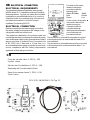
1 ELECTRICAL
• This cooker hood is tted with a 3-core mains cable with a standard 10/16A earthed plug.
• Alternatively the hood can be connected to the mains supply via a double-pole switch having 3mm
minimum contact gap on each pole.
• Before connecting to the mains supply ensure that the mains voltage corresponds to the voltage on
the rating plate inside the cooker hood.
• Technical Specication: Voltage 220-240, single phase ~50/60Hz.
2 INSTALLATION ADVICE
• Ensure the cooker hood is tted in compliance with the recommended xing heights.
• To ensure the safe operation of this cooker hood, we recommend that the hood should not be tted
below 65cm (for electric) or (70cm for gas) the measurements taken from the surface of the cooking
appliance to the underside of the cooker hood.
• It is a possible re risk if the hood is not sited as recommended.
• To ensure the best results, the cooking fumes should be able to rise naturally towards the inlet grilles
on the underside of the cooker hood and the cooker hood should be positioned away from doors and
windows, which will create turbulence.
• Ducting
• If the room where the hood is to be used contains a fuel-burning appliance such as a central heating
boiler then its ue must be of the room sealed or balanced ue type.
• If other types of ue or appliances are tted ensure that there is an adequate supply of fresh air to the
room. Ensure the kitchen is tted with an airbrick, which should have a cross-sectional measurement
equivalent to the diameter of the ducting being tted, if not larger.
• The ducting system for this cooker hood must not be connected to any existing ventilation system,
which is being used for any other purposes or to a mechanically controlled ventilation ducting.
• The ducting used must be made from re retardant materials and the correct diameter must be used,
as incorrect sized ducting will affect the performance of this cooker hood.
• When the cooker hood is used in conjunction with other appliances supplied with energy other than
electricity, the negative pressure in the room must not exceed 0.04 mbar to prevent the fumes from
combustion being drawn back into the room.
• The appliance is for domestic use only and should not be operated by children or people who are
inrm without supervision.
• This appliance must be positioned so that the wall socket is accessible.
• This appliance is not intended for use by persons (including children) with reduced physical, sensory
or mental capabilities, or lack of experience and knowledge, unless they have been given supervision or
instruction concerning use of the appliance by a person responsible for their safety.
Children should be supervised to ensure that they do not play with the appliance.
3 FITTING
Any permanent electrical installation must comply with the latest regulations concerning this type of
installation and a qualied electrician must carry out the work. Non-compliance could cause serious
accidents or injury and would deem the manufacturers guarantee null and void.
IMPORTANT - The wires in this mains lead are coloured in accordance with the following code :
- green / yellow : earth - blue : neutral - brown : live
As the colours of the wires in the mains lead of this appliance may not correspond with the coloured

7
GB
markings identifying the terminals in your plug, proceed as follows.
- The wire which is coloured green and yellow must be connected to the terminal in the plug which is
marked with the letter E or by the earth symbol or coloured green or green and yellow.
- The wire which is coloured blue must be connected to the terminal which is marked with the letter N or
coloured black.
- The wire which is coloured brown must be connected to the terminal which is marked with the letter L or
coloured red.
ATTENTION: Do not forget to use adequate plugs to the support brackets. Enquire after the
manufacturers. Do an embedding if necessary. The manufacturer accepts no responsibility in
case of a faulty hanging due to the drilling and the setting up of plugs.GB
1) Draw a vertical line onto the wall from the centre of the cooking appliance up to the ceilling, using a
spirit level and a marker pen as illustrated in Fig. 1 - item 1. This is to ensure the correct alignment
of the chimney hood.
2) Place the brackets item 2 on the wall about 1 or 2 mm from the ceiling or from the upper limit, aligning
its centre on the vertical line. Mark the two eyelet holes of the bracket onto the wall. Drill the holes
for the xing bracket using an 8 mm masonry bit. Fix the chimney bracket item 2 using the 4.5 x 50
mm screws and rawl plugs supplied.
3) Mark a point on the vertical line at a distance from the cooking appliances of:
d = 1070 mm (Measurement without splashback).
d = height of the splashback (400 mm) + 670 mm (Measurement with splashback).
The distance H is the minimum height in mm from the cooking appliances to the bottom edge item 3 of
the front panel of the hood. Draw a horizontal line through the vertical as illustrated in Fig. 1.
Splashback (optional): When a splashback is to be tted, the distance between the hood and the cook-
ing appliances will be determined by the height of the splashback item B and whether or not there
is a raised back on the worktop. The splashback is to be installed before installing the canopy. If
the splashback is to be xed to the wall using both the top and bottom xing holes, Care must be
taken to ensure that the splashback is tted at the correct height before xing the base units or at
least the worktop covering them. As this is a complex operation, it should only be undertaken by
the technician installing the kitchen units or by a competent person who knows the nal dimensions
of the units.
Mark the hole centres for the canopy xing brackets item 4 at item B mm as illustrated in Fig. 3.
Drill the 4 holes for the xing brackets using an 8 mm masonry bit. Fix the wall brackets item 4 using
the 4.5 x 45 mm screws and rawl plugs supplied.
4) Hook the canopy item 5 onto the wall brackets item 4 as illustrated in Fig. 3. To ensure the cooker
hood is aligned correctly adjust the screws on the top of the canopy as illustrated in Fig. 3. When the
hood is aligned correctly mark the hole centre on the wall for the security xing screw item8, which
is located in the right hand bracket on the top of the canopy. Unhook the canopy from the wall and
drill the hole for the security xing screw. Hook the canopy onto the wall and x the No 4,5 x 50mm
headed screw and rawl plug to secure the canopy to the wall.
5) Ducting:
The hood is more effective when used in the extraction mode (ducted to the outside). When the cooker
hood is ducted to the outside, charcoal lters are not required.The ducting used must be 150 mm (6
INS), rigid circular pipe and must be manufactured from re retardant material, produced to BS.476
or DIN 4102-B1. Wherever possible use rigid circular pipe which has a smooth interior, rather than
the expanding concertina type ducting.
Maximum length of ducting run:
- 4 metres with 1 x 90° bend.
- 3 metres with 2 x 90° bends.
- 2 metres with 3 x 90° bends.
The above assumes our 150 mm (6 INS) ducting is being installed. Please note ducting components
and ducting kits are optional accessories and have to be ordered, they are not automatically sup-

8
plied with the chimney hood.
IN THE EXTRACTION MODE:
a. Place the anti-backow ats item 8 over the round outlet item 6, the telescopic duct and connect the
ducting 150mm (6 INS) over the round outlet on top of the canopy and secure the connections with
appropriate clamping rings or adhesive tape (Fig. 6).
b. Remove the grease lters (see paragraph Maintenance) Fig. 5 being sure that the connector of the
mains cable is correctly inserted in the socket placed on the sides of the fan. Before tting the chimney
to the canopy make the electrical connection as described in the section titled ELECTRICAL. When
the electrical connection has been made, test the lights and the fan motor.
c. Each chimney stack consists of two sections. Fit the upper sections (Fig. 1 - item 7a & b) rst by
expanding the chimneys slightly to allow them to clamp around the bracket item 2 and secure the
chimney stacks to the brackets using the two M4 screws item 12c provided. Fit the lower chimney
sections by expanding the chimneys slightly to allow them from the top of the canopy to clamp around
the upper chimney sections.
d. Fit the deector Item 9.
IN THE RECIRCULATION MODE:
a. Fit the recirculation spigot R onto the upper chimney wall bracket using the same xing screws (Fig.
2 item 2).
b. Connect the ducting 150mm (6 INS) not provided between motors item 6 and the recirculation spigot
and secure the connections with appropriate clamping rings or adhesive tape.
c. Remove the grease lters (see paragraph Maintenance) Fig. 5 being sure that the connector of the
feeding cable is correctly inserted in the socket placed on the side of the fan. Before tting the chimney
to the canopy make the electrical connection as described in the section titled ELECTRICAL. When
the electrical connection has been made, test the lights and the fan motor.
d. Insert the charcoal lter into the base of the motor housing and secure the lter with two metal secur-
ing straps item A as illustrated in Fig. 4.
e. Each chimney stack consists of two sections. Fit the upper sections (Fig. 1 - item 7a & b) rst by
expand-ing the chimneys slightly to allow them to clamp around the bracket item 2 and secure the
chimney stacks to the brackets using the two M4 screws item 12c provided. Fit the lower chimney
sections by expanding the chimneys slightly to allow them from the top of the canopy to clamp around
the upper chimney sections.
f. Fit the deector Item 9.
GB

9
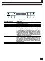
4 OPERATION
GB
T
1
T
2
T3
T
4
T
5
L
Control panel
TOUCH CONTROL FUNCTION
T1 ON/OFF Motor Switches the hood motor on and off. The latest selected
speed appears on the display.
T2 Speed - Decreases the suction speed: V3 → V2 → V1
T3 Speed + Increases the suction speed: V1 → V2 → V3
T4 Intensive speed Activates the intensive speed from any previously selected
speed. The intensive speed can be activated even when the
motor is OFF. By pressing the same touch control once again
or by switching off the motor this function can be deacti-
vated. Intensive speed cannot be activated when the delay
function is on. Intensive speed has been timed at 10 minutes:
H appears on the display and a spot down on the right side
flashes once a second. After 10 minutes the system activates
automatically the latest selected speed.
T5 Delay Activates and deactivates the delayed shutdown of the hood
(motor + lighting) at 30 minutes: the selected speed of the
hood appears on the display and a spot down on the right
side flashes once a second. By pressing the same touch con-
trol once again or by switching off the motor delay function
can be deactivated.
L Lighting Turns light on and off.

10
5 USEFUL HINTS
• To obtain the best performance it is advisable to switch ‘ON’ the cooker hood a few minutes (in the
boost setting) before you start cooking and you should leave it running for approximately 15 minutes after
nishing.
• IMPORTANT: NEVER DO FLAMBÉ COOKING UNDER THIS COOKER HOOD
• Do not leave frying pans unattended during use as over-heated fat and oil might catch re.
• Do not leave naked ames under this cooker hood.
• Switch ‘OFF’ the electric and gas before removing pots and pans.
• Ensure heating areas on your hotplate are covered with pots and pans when using the hotplate
and cooker hood simultaneously.
6 MAINTENANCE
Before carrying out any maintenance or cleaning isolate the cooker hood from the mains supply.
The cooker hood must be kept clean; a build up of fat or grease can be a re hazard.
Casing
• Wipe the cooker hood frequently with a clean cloth, which has been immersed in warm water containing
a mild detergent and wrung out.
• Never use excessive amounts of water when cleaning particularly around the control panel.
• Never use scouring pads or abrasive cleaners.
• Always wear protective gloves when cleaning the cooker hood.
Metal Grease Filters
The metal grease lters absorb grease and dust during cooking to help keep the cooker hood clean
inside. The grease lters should be cleaned once a month or more frequently if the hood is used for more
than 3 hours per day.
To remove and replace the metal grease lters
• Remove the metal grease lters one at a time by releasing the catches on the lters; the lters can
now be removed.
• The metal grease lters should be washed, by hand, in mild soapy water or in a dishwasher.
• Allow to dry before replacing.
Active Charcoal Filter
The charcoal lter cannot be cleaned. The lter should be replaced at least every three months or more
frequently if the hood is used for more than three hours per day.
To remove and replace the lter
• Remove the metal grease lters.
• Press against the two retaining clips, which hold the charcoal lter in place and this will allow the lter
to drop down and be removed.
• Clean the surrounding area and metal grease lters as directed above.
• Insert the replacement lter and ensure the two retaining clips are correctly located.
• Replace the metal grease lters.
Extraction tube.
Check every 6 months that the dirty air is being extracted correctly. Comply with local rules and regula-
tions with regard to the extraction of ventilated air.
Lighting.
If the lamp fails to function check to ensure it is tted correctly into the holder. If lamp failure has occurred
then it should be replaced with identical replacement.
Do not replace with any other type of lamp and do not t a lamp with a higher rating.
7 GUARANTEE AND AFTER SALES SERVICE
• In the event of any malfunction or anomaly, notify your tter who will have to check the appli-
ance and its connection.
GB

11
GB
• In the event of damage to the mains supply cable, this can only be replaced by at approved repair
centre appointed by the manufacturer who have the necessary tools and equipment to carry out any
repairs properly. Repairs carried out by other persons will invalidate the guarantee.
• Use only genuine spare parts. Should these warnings fail to be observed it could affect the safety of
your cooker hood.
• When ordering spare parts quote the model number and serial number written on the rating plate,
which is found on the casing behind the grease lters inside the hood.
• Proof of purchase will be required when requesting service. Therefore, please have your receipt
available when requesting service as this constitutes the date from which your guarantee commenced.
This Guarantee does not cover :
- Damage or calls resulting from transportation, improper use or neglect, the replacement of any light
bulbs or lters or removable parts of glass or plastic.
These items are considered to be consumable under the terms of this guarantee.
8 REMARKS
This appliance complies with European regulations on low voltages Directive 2006/95/CE on electrical
safety, and with the following European regulations: Directive 2004/108/CE on electromagnetic compat-
ibility and Directive 93/68 on EC marking.
When this crossed-out wheeled bin symbol
is attached to a product it means the product is cov-
ered by the European directive 2002/96/EC.Your product is designed and manufactured with high quality
materials and components, which can be recycled and reused.Please inform yourself about the local
separate collection system for electrical and electronic product. Please act according to your local rules
and do not dispose of your old products with your normal household waste. The correct disposal of your
old product will help prevent potential negative consequences for the environment and human health.
OPERATION

12
Wir danken Ihnen für Ihre Kaufentscheidung und das Vertrauen, welches Sie mit dem Kauf dieses Roblin-
Produktes bewiesen haben.
Dieses Gerät wurde mit einem hohen Maß an Kreativität entwickelt und mit größter Sorgfalt gefertigt.
Um volle Zufriedenheit mit Leistung und Funktion dieser Dunstesse zu erlangen und zu erhalten, empfeh-
len wir dringend, sowohl die Montageanweisung sorgfältig zu beachten und danach zu arbeiten als
auch die « Gebrauchs- und Wartungshinweise « aufmerksam zu lesen und anzuwenden.
Diese Gebrauchsanleitung gilt für mehrere Geräte-Ausführungen. Es ist möglich, dass einzelne Ausstat-
tungsmerkmale beschrieben sind, die nicht auf Ihr Gerät zutreffen.
1 NETZANSCHLUSS
• Die Dunstabzugshaube ist mit einer Anschlußleitung der Art HO5VVF 3 x 0,75 mm
2, die einen Schutz-
stecker 10 / 16 A enthält, ausgestattet. Das entspricht Schutzklasse 1.
Nennspannung : 220-240 V - Wechselstrom : 50/60 Hz.
• Es ist sicherzustellen, daß die Netzspannung den Anschlußwerten auf dem Typenschild im Inneren
der Dunstesse entspricht.
• Beim Anschluß der Dunstesse an das Wechselstromnetz ist ein zweipoliger Schalter mit einem Öff-
nungsweg von wenigstens 3 mm für jeden Pol zwischenzuschalten.
2 MONTAGEHILFEN
• Die Mindest- und Höchstabstände zwischen der Dunstesse und der Kochäche sind zu berücksichtigen.
Wir empfehlen Ihnen einen Abstand von 0,65 m bis 0,70 m über der Kochäche einzuhalten,
um einen optimalen Betrieb des Gerätes zu gewährleisten. Jedoch ist es streng verboten, Dunstessen
oder Einbaugeräte mit einem Abstand, der niedriger als 0,65 m von der Kochäche ist, einzubauen
(Entzündungsgefahr der Filter). Beachten Sie die richtige Ableitung der Kochschwaden (Luftzug kann
Turbulenzen verursachen).
• Der Außendurchmesser am Gebläseabgang des Gerätes ist für die Wahl des Abluft-Rohrsystems
zu berücksichtigen : Die Dunstesse darf keinesfalls an eine Entlüftungsleitung mit Unterdruck angeschlos-
sen werden. Die Abluft darf nicht in einen Schornstein geleitet werden, der für die Abgase von Koch- oder
Heiz-Geräten, (Kohle-, Öl- oder Gas-Öfen oder -Herde) benutzt wird.
• Die Kochstelle (und damit auch die Dunstesse) so planen und installieren, daß möglichst kurze
Wege für eventuelle Abluft-Rohrleitungen erreicht werden. (so wenige Umlenkungen [90°-Bögen] wie
möglich! Keine Querschnittsverengungen!
• Die gute Erneuerung der Luft in der Küche ist zu beachten. Denken Sie daran, einen oder mehrere
Lufteintritte durch eine Öffnung, die den gleichen Durchmesser hat wie die Abluftleitung, vorzusehen.
• Sorgen Sie für eine ausreichende Zuluft, wenn ein Koch- oder anderes Gerät die Luft des Raumes,
in dem die Dunstesse eingebaut ist, gleichzeitig verwendet. Ein gefahrloser Betrieb ist möglich, wenn bei
gleichzeitigem Betrieb von Dunstesse und Feuerstätte im Raum ein Unterdruck von höchstens 0.04 mbar
erreicht wird und ein Rücksaugen der Feuerstättenabgase vermieden wird.
Das Gerät muß so installiert werden, daß der Geräte-Stecker leicht erreichbar ist.
• Dieses Gerät darf nicht von Personen, auch Kindern, mit verminderten psychischen, sensorischen und
geistigern Fähigkeiten, oder von Personen ohne Erfahrung und Kenntnisse benutzt werden, sofern sie
nicht von für ihre Sicherheit verantwortlichen Personen beaufsichtigt und beim Gebrauch des Geräts
angeleitet werden.
Kinder dürfen sich nicht unbeaufsichtigt in der Nähe des Geräts aufhalten und auf keinen Fall mit dem
Gerät spielen.
3 MONTAGE DES GERÄTES
Montage und Anschluß müssen von einem qualizierten Installateur* durchgeführt werden.
(*) Wenn diese Bedingung nicht eingehalten wird, wird die Garantie des Herstellers, sowie jeder
Anspruch im Falle eines Unfalles aufgehoben.
Achtung ! Bitte beachten Sie bei der Montage das Gewicht der kompletten Dunstesse. Die Tragfä-
higkeit der Decke oder alternativ der Trägerplatte für diese Zugbelastung muss vor der Montage
D

13
geprüft und gegebenenfalls durch die Anbringung von geeigneten Befestigungs-oder Stabilisie-
rungselementen hergestellt werden. Kann eine hinreichende Tragfähigkeit nicht sichergestellt
werden, ist von einer Montage abzusehen.
1) An der Wand eine vertikale Linie 1 (Abb. 1) bis zur Decke zeichnen (Mittellinie des Bereiches, indem
die Haube montiert werden soll), um die zu montierenden Einzelteile vertikal ausrichten zu können.
2) Einen der beiden Bügel 2 (Abb. 1) ca. 1-2 mm von der Decke oder der oberen Begrenzung an die
Wand legen und den Mittelpunkt auf der vertikalen Linie ausrichten. Die beiden ösenförmigen Bohrlöcher
des Bügels an der Wand markieren.
3) Einen Punkt auf der vertikalen Linie kennzeichnen, der folgenden Abstand zur Kochmulde aufweist:
d = min. 1070 (Maß ohne Rückwand).
d =Rückwandhöhe (400 mm) + 670 mm (Maß mit Rückwand). Das Maß H ist die Mindesthöhe in mm
von der Kochmulde zur unteren Frontkante 3.
Rückwand (Optional): Der Abstand der Haube von der Kochmulde wird in diesem Fall von der Höhe
der Rückwand B und des eventuell anzubringenden Aufsatzes an der Arbeitsplatte bestimmt. Die Rück-
wand wird vor Montage des Haubenkörpers angebracht; will man die Rückwandoben und unten mit der
Wand verschrauben, muss sie auf die gewünschte Höhe ausgerichtet werden, bevor der Unterschrank
oder die Arbeitsplatte montiert wird. Da es sich hierbei um einen relativ komplizierten Vorgang handelt,
sollte er nur vom Küchenmontagepersonal oder von fachlich geschulten Personen, die die Endmasse
der Möbel genau kennen, durchgeführt werden.
Für die Unterkante des Gerätes eine Einbauhöhe (3) bestimmen,um die Stützen zu positionieren. (Figur
3, Pos. 4) (Abb. 1& 2)
4) Montage des Haubenkörpers: Der Haubenkörper (5) wird an den Wandstützen befestigt. Die Regelung
und das Ausrichten der Dunstesse von außen mit den Schrauben 5 x 10 der Stützenund mit den zwei
Schrauben 5 x 25 mm kontrollieren. Nachdem Sie alle Einstellungen durchgeführt haben, verriegeln Sie
die Dunstesse durch dieBefestigungsschraube (8), um das unbeabsichtigte Aushängen zu vermeiden.
Diese positiveBefestigungsschraube ist durch eine farbige Aufschrift gekennzeichnet, die sich im Oberteil
desGeräte-Gehäuses bendet.
5) Anschluss für Abluft- oder Umluftbetrieb:
• Abluftbetrieb
a- Die Rückstauklappe (Pos .8) am Gerätsausgang anbringen (Pos. 6), der Teleskopscheide auf den
Flansch des Gerätes einfügen. Schlauch am Gerätsausgang anbringen (Abb. 6) und anschliessen. Beim
Anschluss passende Schlauchschellen oder Klebeband benutzen.
b- Entfernen Sie die Fettlter (s. Abschnitt „Wartung“) und versichern Sie sich, dass die Kabelverbindung
in die Steckdose des Gebläses einwandfrei montiert wird (Abb. 5). Das Gerät ans Wechselstromnetz
anschliessen (siehe Abschnitt Netzanschluss) und Funktion von Beleuchtung, Motor und der elektro-
nischen Steuerung (Gebläseleistung) prüfen.
c- Den Oberkamin in den Teleskop-Unterkamin (Abb.1 Pos.7 a+b) einfügen und mit den beigelegten
Schrauben M 4 (Pos. 12 c) an die Stütze (Pos. 2) hängen. Danach den Oberkamin um den Hauben-
körper falzen.
d- die Ablenkplatte Pos. 9 festzulegen.
• Umluftbetrieb
a- Den Umluftadapter R an den Oberkamin hängen. Der Umluftadapter wird mit denselben Schrauben
wie für die Oberkaminstütze befestigt (Abb. 2 – Pos. 2).
b- Ein Verbindungsrohr/Schlauch mit passendem Durchmesser (nicht im Lieferumfang) am Lufteintritt
des Umluftadapters und am Gebläseausgang (Pos. 6) anschliessen. Beim Anschluss passende
Schlauchschellen oder Klebeband benutzen.
D

14
c- Entfernen Sie die Fettlter (s. Abschnitt „Wartung“) und versichern Sie sich, dass die Kabelverbindung
in die Steckdose des Gebläses einwandfrei montiert ist (Abb. 5). Das Gerät ans Wechselstromnetz
anschliessen (siehe Abschnitt Netzanschluss) und Funktion von Beleuchtung, Motor und der elektro-
nischen Steuerung (Gebläseleistung) prüfen.
d- Die Stütze der Aktivkohle-Filters befestigen und mittels Druck auf die Elemente A (Abb. 4) Aktivkohle-
Filterkassette einrasten.
e- Den Oberkamin in den Teleskop-Unterkamin (Abb.1 Pos.7 a+b) einfügen und den Oberkamin mit
den beigelegten Schrauben M 4 ( Pos. 12 c) an die Stütze (Pos. 2) hängen. Danach den Oberkamin
um den Haubenkörper falzen.
f- die Ablenkplatte Pos. 9 festzulegen.
D

15
BETRIEB DES GERATES
D
T
1
T
2
T3
T
4
T
5
L
Bedienfeld
TASTE FUNKTIONEN
T1 Motor ON/OFF Schaltet den Gebläsemotor ein und aus. Auf dem Display wird die
zuvor eingestellte Geschwindigkeitsstufe angezeigt.
T2 Geschwindigkeit - Erhöht die Geschwindigkeit des Motors: V3 → V2 → V1
T3 Geschwindigkeit + Verringert die Geschwindigkeit des Motors: V1 → V2 → V3
T4 Intensivstufe Aktiviert die Intensivstufe von jeder Geschwindigkeitsstufe aus
oder bei ausgeschaltetem Motor. Zum Ausschalten einfach die sel-
be Taste erneut drücken oder den Motor ausschalten. Bei aktivier-
ter Delay-Funktion lässt sich die Intensivstufe nicht aktivieren. Die
Intensivstufe dauert 10 Minuten: Auf dem Display wird H ange-
zeigt und der Punkt unten rechts blinkt einmal pro Sekunde. Nach
10 Minuten kehrt das System automatisch in die zuvor eingestellte
Geschwindigkeitsstufe zurück.
T5 Delay Aktiviert und deaktiviert den Modus Komplettes Ausschalten der
Haube (Motor + Beleuchtung) nach 30 Minuten: Auf dem Display
wird die Geschwindigkeitsstufe des Motors angezeigt und der
Punkt unten rechts blinkt einmal pro Sekunde. Zum Deaktivieren
der Delay-Funktion die selbe Taste erneut drücken oder den Motor
ausschalten.
L Beleuchtung Schaltet die Beleuchtung der Haube ein und aus.

16
5 NUTZUNG
• Um ein optimales Absaugen der Kochschwaden zu erzielen, wird empfohlen, das Gerät vor dem
Kochen einzuschalten und nach dem Kochen noch einige Zeit nachlaufen zu lassen. Für die Speisen, die
wenig Dampf entwickeln, verwenden Sie vorzugsweise die kleine Geschwindigkeit.
• WICHTIG : NIEMALS UNTER DEM GERÄT FLAMBIEREN.
Niemals eine große Flamme bei eingeschalteter Dunstesse unbedeckt lassen.
Wenn der Topf weggenommen wird, ist die Flamme abzuschalten oder für einen kurzen Zeitraum auf
kleinste Stellung zu drehen, trotzdem aber unbedingt im Auge zu behalten.
Frittiergeräte, die unter der Dunstesse betrieben werden, sind während der gesamtem Betriebsdauer zu
beaufsichtigen: überhitztes Öl kann sich entzünden und die Haube in Brand setzen.
6 WARTUNG UND REINIGUNG
Vor jedem Eingriff in das Gerät immer den Netzstecker ziehen, oder die Sicherung herausdrehen bzw.
die Stromzufuhr unterbrechen.
Bei der Konstruktion des Gerätes wurde besonders die Wartungs-Freundlichkeit berücksichtigt.
• Herausnehmen des Metalllters :
Es ist unerläßlich, diese Filter REGELMÄßIG falls notwendig auch in kurzen Intervallen, mit der Hand
(lauwarmes Wasser mit Waschmittel und Spülen) oder in der Geschirrspülmaschine zu REINIGEN.
Diese Maßnahmen vermindern die Brandgefahr (starke Fettrückstände sind leicht brennbar).
• Gehäuse.
Keine nassen Tücher für die Reinigung der Oberächen der Dunstesse verwenden. Es sollen nur milde
Reinigungsmittel und leicht feuchte Tücher verwendet werden. Keine Gegenstände in die Luftaustrittsöff-
nung stecken. Nicht in die Luftaustrittsöffnung greifen.
• Abluftleitung:
Kontrollieren Sie von Zeit zu Zeit, daß der Luftkanal nicht verstopft ist. Diese Prüfung muß halbjährlich
durchgeführt werden. Die behördlichen Anforderungen, für die Ableitung der Abluft, sind zu berücksichti-
gen.
• Beleuchtung:
Bei Leuchtmittel-Wechsel in jedem Fall den Schalter der Beleuchtung ausschalten.
Die Art des Leuchtmittels nicht wechseln. Leistung nicht überschreiten.
7 GARANTIE UND KUNDENDIEST
• Bei Versagen des Gerätes benachrichtigen Sie Ihren Installateur, der das Gerät und seine Installation
überprüfen wird.
• Wenn die Geräte-Zuleitung beschädigt wurde, darf diese nur von einer Reparaturwerkstatt ersetzt
werden, die von dem Hersteller anerkannt ist, weil Sonderwerkzeuge nötig sind. Haube komplett abschal-
ten.
• Stets nur Original-Ersatzteile verwenden.
• Sollte diese Vorschrift nicht eingehalten werden, könnte die Sicherheit des Gerätes beeinträchtigt
werden. Außerdem erlischt die Garantie.
• Bei der Bestellung von Ersatzteilen geben Sie bitte die Nummer des Gerätes, die sich auf dem
Typenschild hinter dem Gehäuse bendet, an.
• Für die Anwendung der vertraglicher Garantie wird nur die Einkaufsrechnung des Gerätes verbindlich
anerkannt. Von der Garantieleistung ausgenommen sind:
- Die Beleuchtung : Klassik - und Halogenbeleuchtung
- Die Filter (Die Filter sind als Verbrauchsgut anzusehen).
8 WICHTIGE HINWEISE
Dieses Gerät entspricht den europäischen Niederspannungsrichtlinien 2006/95/EWG zur elek-
trischen Sicherheit, den europäischen Richtlinien 2004108/EWG zur elektromagnetischen Ver-
träglichkeit und den Richtlinien 93/68/EWG zur CE Kennzeichnung.
D

17
D
Das Symbol auf dem Produkt oder seiner Verpackung weist darauf hin, dass dieses Pro-
dukt nicht als normaler Haushaltsabfall zu behandeln ist, sondern an einem Sammelpunkt für das
Recycling von elektrischen oder elektronischen Geräten abgegeben werden muss. Durch Ihren
Beitrag zum korrekten Entsorgen dieses Produktes schützen Sie die Umwelt und die Gesundheit
Ihrer Mitmenschen. Umwelt und Gesundheit werden durch falsches Entsorgen gefährdet. Weitere
Informationen über das Recycling dieses Produktes erhalten Sie von Ihrer kommunalen Behörde,
den örtlichen Müllentsorgungsunternehmen oder von Ihrem Fachhändler.

18
I
La ringraziamo per la ducia accordataci nell’aver scelto un prodotto della gamma ROBLIN. Questo
apparecchio è stato studiato e realizzato con la massima cura, secondo i più alti criteri di qualità. Le rac-Le rac-
comandiamo di leggere attentamente questo opuscolo, nel quale troverà le istruzioni per installare,
utilizzare e conservare al meglio il suo apparecchio ed ottenere dal suo acquisto il massimo dei beneci.
Questo libretto di istruzioni per l’uso è previsto per più versioni dell’ apparec-chio. É possibile che siano
descritti singoli particolari della dotazione, che non riguardano il Vostro apparecchio.
1 COLLEGAMENTO ELETTRICO
• La cappa é dotata di un cavo di alimentazione di tipo HOSVVF 3x 0,75 mm² e comporta una spina
normalizzata 10/16 A con sistema di terra.
Protezione : classe 1. Tensione di alimentazione : 220-240 V mono - 50/60 Hz.
Vericare che la tensione di rete sia identica ai valori indicati sull’etichetta all’interno della cappa.
• Se la cappa é collegata direttamente all’impianto elettrico senza la sua spina, è necessario istallare
prima della cappa un interruttore omnipolare con un’apertura di contatto di 3 mm.senza interrompere il
lo della terra (giallo/verde).
2 CONSIGLI DI INSTALLAZIONE
• Per un funzionamento ideale, vi consigliamo un’altezza di posa situata entro 0,65 m e 0,70 m al di sopra
del piano di cottura. Tuttavia, é formalmente vietata l’istallazione di qualsiasi cappa o gruppo aspirante
ad una distanza inferiore a 0,65 m dal piano di cottura (rischio di incendio dei ltri). I fumi devono salire
naturalmente verso la zona aspirante (attenzione alla correnti d’aria che potrebbero provocare delle
turbolenze).
• Rispettare il diametro di uscita dell’apparecchio : la cappa non deve in alcun caso essere collegata
ad un condotto di ventilazione meccanica controllata (V.M.C.).
• Qualora l’aria viziata fosse scaricata in un condotto d’evacuazione, vericare che quest’ultimo non sia
già utilizzato per evacuare gas o fumi provenienti da apparecchi alimentati da un’energia diversa da
quella elettrica.
• Posizionare il piano di cottura in corrispondenza della zona di evacuazione della cappa ed evitare la
posa di gomiti che ne potrebbero ridurre la potenza.
• In tutti i casi di istallazione, fare attenzione al ricambio d’aria della cucina. Istallare una o più griglie
d’aerazione di misura uguale o superiore al diametro del tubo di evacuazione per evitare di mettere il
locale in depressione.
• Prevedere un’aerazione sufciente qualora un apparecchio di cottura o altro utilizzi simultaneamente
l’aria dell’ambiente in cui é situata la cappa. La depressione massima creata nel locale deve essere inferi-deve essere inferi-
ore a 0,04 mbar per evitare un ritorno di gas di combustione.
• L’apparecchio deve essere posizionato in modo che la spina sia accessibile.
• Questo apparecchio non deve essere utilizzato da persone (bambini inclusi) con ridotte capacità
psichiche, sensoriali o mentali, oppure da persone senza esperienza e conoscenza, a meno che non
siano controllati o istruiti all’uso dell’apparecchio da persone responsabili della loro sicurezza.
I bambini devono essere supervisionati per assicurarsi che non giochino con l’apparecchio.
3 POSA DELL’ APPARECCHIO
Il montaggio ed il collegamento devono esere realizzati da un istallatore qualicato *.
(*) Il non rispetto di questa condizione provocherà l’annullamento della garanzia del costruttore e tutti i
ricorsi in caso di incidente.
Attenzione: usare dei tasselli adatti al supporto, informarsi presso i fabbricanti, effettuare una
sigillatura se necessario. La società declina ogni responsabilità in caso di agganciatura difettosa
dovuta alla perforazione ed al ssaggio.
1) Tracciare sulla parete una linea verticale no al softto, al centro della zona prevista per il montaggio
della cappa (Fig. 1, rif. 1); questa operazione serve ad effettuare l’allineamento verticale delle diverse
parti della cappa.
La pagina si sta caricando...
La pagina si sta caricando...
La pagina si sta caricando...
La pagina si sta caricando...
La pagina si sta caricando...
La pagina si sta caricando...
La pagina si sta caricando...
La pagina si sta caricando...
La pagina si sta caricando...
La pagina si sta caricando...
La pagina si sta caricando...
La pagina si sta caricando...
La pagina si sta caricando...
La pagina si sta caricando...
La pagina si sta caricando...
La pagina si sta caricando...
La pagina si sta caricando...
La pagina si sta caricando...
La pagina si sta caricando...
La pagina si sta caricando...
La pagina si sta caricando...
La pagina si sta caricando...
La pagina si sta caricando...
La pagina si sta caricando...
La pagina si sta caricando...
La pagina si sta caricando...
La pagina si sta caricando...
La pagina si sta caricando...
-
 1
1
-
 2
2
-
 3
3
-
 4
4
-
 5
5
-
 6
6
-
 7
7
-
 8
8
-
 9
9
-
 10
10
-
 11
11
-
 12
12
-
 13
13
-
 14
14
-
 15
15
-
 16
16
-
 17
17
-
 18
18
-
 19
19
-
 20
20
-
 21
21
-
 22
22
-
 23
23
-
 24
24
-
 25
25
-
 26
26
-
 27
27
-
 28
28
-
 29
29
-
 30
30
-
 31
31
-
 32
32
-
 33
33
-
 34
34
-
 35
35
-
 36
36
-
 37
37
-
 38
38
-
 39
39
-
 40
40
-
 41
41
-
 42
42
-
 43
43
-
 44
44
-
 45
45
-
 46
46
-
 47
47
-
 48
48


ROBLIN Vista Manuale del proprietario
- Categoria
- Cappe da cucina
- Tipo
- Manuale del proprietario
- Questo manuale è adatto anche per
in altre lingue
- English: ROBLIN Vista Owner's manual
- français: ROBLIN Vista Le manuel du propriétaire
- español: ROBLIN Vista El manual del propietario
- Deutsch: ROBLIN Vista Bedienungsanleitung
- Nederlands: ROBLIN Vista de handleiding
Documenti correlati
-
ROBLIN LIDO DESIGN MURALE Manuale del proprietario
-
-
-
-
-
-
-
-
-