ABB NextMove e100 Quick Installation Manual
- Tipo
- Quick Installation Manual

ABB motion control
Quick installation guide
NextMove e100
English . . . . . . . . . . . . . . . . . . . . . . . . . 3
Deutsch. . . . . . . . . . . . . . . . . . . . . . . . 11
Español. . . . . . . . . . . . . . . . . . . . . . . . 19
Français . . . . . . . . . . . . . . . . . . . . . . . 27
Italiano . . . . . . . . . . . . . . . . . . . . . . . . 35
Svenska . . . . . . . . . . . . . . . . . . . . . . . 43
中文. . . . . . . . . . . . . . . . . . . . . . . . . . . 51
LT0305A02
Effective: 2017-06-21
2017 ABB Oy. All rights reserved.
LT0305A01.book Page 1 Wednesday, June 21, 2017 2:10 PM

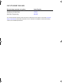
List of related manuals
You can find manuals and other product documents in PDF format on the Internet. See section Document
library on the Internet on the inside of the back cover. For manuals not available in the Document library,
contact your local ABB representative.
Drive hardware manuals and guides Code (English)
NextMove e100 Motion Controller Installation Manual MN1941WEN
NextMove e100 Wall Chart LT0230...
Mint Basic Programming MN1955
LT0305A01.book Page 2 Wednesday, June 21, 2017 2:10 PM

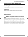
Quick Installation Guide – NextMove e100 3
Quick Installation Guide – NextMove e100
About this guide
This guide contains very basic information about the mechanical and electrical
installation of the NextMove e100.
Applicability
Applies to all models of NextMove e100, part numbers beginning NXE100...
Related documents
For a list of related documents in English, see the inside of the front cover.
Safety instructions
WARNING! All electrical installation and maintenance work on the product
should be carried out by qualified electricians only.
Never work on the drive, the braking chopper circuit, the motor cable or the motor
when input power is applied to the drive. After disconnecting the input power, always
wait for 5 minutes to let the intermediate circuit capacitors discharge. Always ensure
by measuring that no voltage is actually present.
A rotating permanent magnet motor can generate a dangerous voltage. Lock the
motor shaft mechanically before connecting a permanent magnet motor to the drive,
and before doing any work on a drive system connected to a permanent magnet
motor.
LT0305A01.book Page 3 Wednesday, June 21, 2017 2:10 PM

4 Quick Installation Guide – NextMove e100
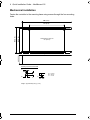
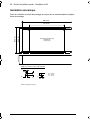
Mechanical installation
Fasten the controller to the mounting base using screws through the four mounting
holes.
140
(5.51)
129
(5.08)
170 (6.69)
250 (9.84)
40.3
(1.59)
A
A
B
C
A = 4.5 mm
B = 10 mm
C = 11 mm
All dimensions shown as
mm (inches)
Drawings not to scale
Mounting keyhole and slot detail
Weight:: Approximately 700 g (1.5 lb)
LT0305A01.book Page 4 Wednesday, June 21, 2017 2:10 PM

Quick Installation Guide – NextMove e100 5
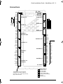
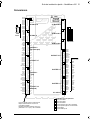
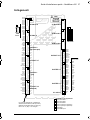
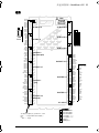
Connections
X12 AIN 0-1
& relay
X7 Encoder2
X6 Encoder1
X4 DOUT 8-11
X2 STEP 0-1
5
6
7
2
3
4
1
1
1
X11 DOUT 0-7
1
X10 DIN 0-3
(fast interrupts)
1
X9 DIN 4-11
1
X8 DIN 12-19
1
X13 AOUT 0-3
(demands)
2
X3 STEP 2-3
X5 Encoder0
X1 +24V in
CAN
5
USB
7
2
2
3
4
4
4
Ethernet
Serial
5
6
DIN3
Shield
CREF0
DIN2
Shield
CREF0
DIN1
Shield
CREF0
DIN0
DOUT0
DOUT1
DOUT2
DOUT3
DOUT4
DOUT5
DOUT6
DOUT7
USR V+
USR GND
AIN0+
AIN0-
AGND
AIN1+
AIN1-
Shield
REL COM
REL NC
REL NO
REL COM
1
2
3
4
5
6
7
8
9
10
10
9
8
7
6
5
4
3
2
1
12
11
10
9
8
7
6
5
4
3
2
1
12
11
10
9
8
7
6
5
4
3
2
1
2
1
1
2
3
4
5
6
7
8
9
10
1
2
3
4
5
6
7
8
9
10
1
2
3
4
5
6
7
8
9
10
1
2
3
4
5
6
7
8
9
10
1
2
3
4
5
6
7
8
9
10
11
12
DIN11
DIN10
DIN9
DIN8
DIN7
DIN6
DIN5
DIN4
CREF1
Shield
DIN19
DIN18
DIN17
DIN16
DIN15
DIN14
DIN13
DIN12
CREF2
Shield
CREF2
CREF1
CREF0
USR V+
USR GND
USR V+
DOUT11
DOUT10
DOUT9
DOUT8
Demand0
AGND
Shield
Demand1
AGND
Shield
Demand2
AGND
Shield
Demand3
AGND
Shield
Shield
DIR3+
DIR3-
STEP3+
STEP3-
DGND
Shield
DIR2+
DIR2-
STEP2+
STEP2-
DGND
Shield
DIR3
+5 V
STEP3
(NC)
DGND
Shield
DIR2
+5 V
STEP2
(NC)
DGND
Shield
DIR1+
DIR1-
STEP1+
STEP1-
DGND
Shield
DIR0+
DIR0-
STEP0+
STEP0-
DGND
Shield
DIR1
+5 V
STEP1
(NC)
DGND
Shield
DIR0
+5 V
STEP0
(NC)
DGND
+24 V
0 V
Mating connectors:
Sauro CTF10008
Sauro CTF12008
Sauro CTF02008
9-pin D-type plug (male)
9-pin D-type socket (female)
RJ45 plug
USB type B plug
Tightening torque for terminal block
connections is 0.25 N·m (2.25 lb-in).
Use 60/75 or 75 °C copper (Cu) wire only.
(NC) = Not Connected
For model
NXE100-16xxSx:
LT0305A01.book Page 5 Wednesday, June 21, 2017 2:10 PM

6 Quick Installation Guide – NextMove e100
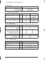
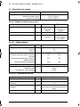
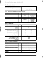
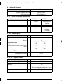
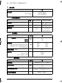
X1 - Input power
X2, X3 - Stepper control outputs
X4, X11 - Digital outputs
X5, X6, X7 - Encoder inputs
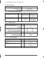
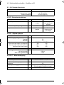
Description Value
Input power
Nominal input voltage
Power consumption
24 V DC (±20%)
50 W (2 A @24 V)
Description Unit NXE100-16xxDx NXE100-16xxSx
Output type RS422 differential
outputs
Darlington
step (pulse) and
direction
Maximum output frequency 5 MHz 500 kHz
Output current 20 mA
(typical)
50 mA
(maximum sink,
per output)
Description Unit Value
USR V+ supply voltage
Nominal
Minimum
VDC
24
12
Output current
Max. source per output, one output on
Max. source per output, all outputs on
Maximum total output current
mA DOUT0-7 DOUT8-11
350 350
62.5 125
500 500
Update interval (Mint) Immediate
Switching time
No load on output
With 7 mA or greater load
100 ms
10 µs
Description Unit Value
Encoder input RS422 A/B Differential, Z index
Maximum input frequency
quadrature
MHz
20
Output power supply to encoders 5V (±5%)
500 mA (maximum total for all axes)
Maximum allowable cable length 30.5 m (100 ft)
LT0305A01.book Page 6 Wednesday, June 21, 2017 2:10 PM

Quick Installation Guide – NextMove e100 7
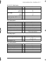
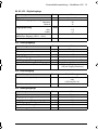
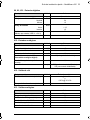
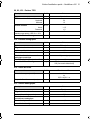
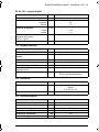
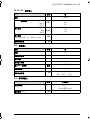
X8, X9, X10 - Digital inputs
X12 - Analog inputs
X12 - Relay output
X13 - Analog outputs
Description Unit Value
Type Opto-isolated
USR V+ supply voltage
Nominal
Minimum
VDC
24
12
Input voltage
Active
Inactive
VDC
> 12
< 2
Input current
(maximum per input, USR V+ = 24 V)
mA 7
Sampling interval ms 1
Description Unit Value
Type Differential
Common mode voltage range V DC ±10
Input impedance kΩ 120
Maximum input current mA 4.9
Input ADC resolution bits 12 (includes sign bit)
Equivalent resolution (±10 V input) mV ±4.9
Sampling interval µs 500 (both inputs enabled)
250 (one input disabled)
All models Unit All models
Contact rating (resistive) 1 A @ 24 V DC
or
0.25 A @ 30 V AC
Operating time (max) ms 5
Description Unit Value
Type Bipolar
Output voltage range V DC ±10
Output current (per output) mA 2.5
Output DAC resolution bits 12
Equivalent resolution mV ±4.9
Update interval ms 1
LT0305A01.book Page 7 Wednesday, June 21, 2017 2:10 PM

8 Quick Installation Guide – NextMove e100
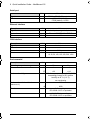
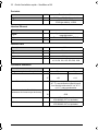
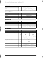
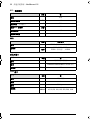
Serial port
Ethernet interface
CAN interface
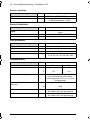
Environmental
Unit All models
Signal RS232 or RS485/422 non-isolated
Bit rates baud 9600, 19200, 38400,
57600 (default), 115200
Description Unit Value
Signal 2 twisted pairs, magnetically isolated
Protocols Ethernet POWERLINK & TCP/IP
Bit rates Mbit/s 100
Description Unit Value
Signal 2-wire, isolated
Channels 1
Protocol CANopen
Bit rates Kbit/s
10, 20, 50, 100, 125, 250, 500, 1000
Description Unit
Operating temperature range Min Max
°C
°F
0
+32
+45
+113
Maximum humidity % 80% for temperatures up to 31 °C (87 °F)
decreasingly linearly to 50% relative
humidity at 45 °C (113 °F),
non-condensing
Maximum installation altitude
(above m.s.l.)
m
ft
2000
6560
Shock 10 G according to
IEC 60068-2-6/27 or equivalent
Vibration 1 G, 10-150 Hz according to
IEC 60068-2-6/27 or equivalent
LT0305A01.book Page 8 Wednesday, June 21, 2017 2:10 PM

Quick Installation Guide – NextMove e100 9
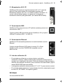
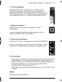
24 V DC supply
The NextMove e100 requires a 24 V DC power supply capable of
supplying 2 A continuously. It is recommended that a separate fused
24 V DC supply is provided for the NextMove e100, with the fuse rated
at 4 A maximum. If digital outputs are to be used, a supply will be
required to drive them - see manual MN1941WEN.
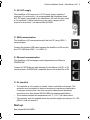
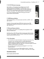
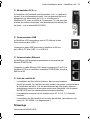
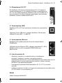
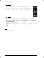
USB communication
The NextMove e100 communicates with the host PC using USB 1.1
communication.
Connect the supplied USB cable between the NextMove e100 and the
host PC's USB port (USB 1.1 or USB 2.0).
Ethernet communication
The NextMove e100 exchanges control parameters over Ethernet
POWERLINK.
Connect a CAT5 Ethernet cable between the NextMove e100 E1 or E2
connector and a POWERLINK compatible drive such as MotiFlex e100.
UL checklist
• The controller is to be used in a heated, indoor controlled environment. The
controller must be installed in clean air according to enclosure classification.
Cooling air must be clean, free from corrosive materials and electrically
conductive dust. See manual MN1941WEN for detailed specifications.
• The maximum ambient air temperature is 45 °C (113 °F) at rated current.
• The controller must be installed where the pollution degree according to UL / IEC
60664-1 shall not exceed 2.
Start-up
See manual MN1941WEN.
LT0305A01.book Page 9 Wednesday, June 21, 2017 2:10 PM

10 Quick Installation Guide – NextMove e100
LT0305A01.book Page 10 Wednesday, June 21, 2017 2:10 PM

Kurzinstallationsanleitung – NextMove e100 11
Kurzinstallationsanleitung – NextMove e100
Über diese Anleitung
Diese Anleitung enthält grundlegende Informationen zur mechanischen und
elektrischen Installation des NextMove e100.
Geltungsbereich
Gilt für alle NextMove e100 Varianten, deren Teilenummern mit NXE100... beginnen.
Zugehörige Dokumente
Eine Liste der zugehörigen Dokumente in Englisch ist auf der Rückseite des
Deckblatts dieses Dokuments zu finden.
Sicherheitsanweisungen
WARNUNG!
Alle elektrischen Installations- und Wartungsarbeiten am Produkt
sollten ausschließlich von qualifizierten Elektrofachkräften durchgeführt werden.
Arbeiten Sie keinesfalls am Antrieb, dem Chopperbremsschaltkreis, dem Motorkabel
oder dem Motor, wenn die Stromversorgung am Antrieb anliegt. Nach Unterbrechung
der Stromversorgung warten Sie 5 Minuten, damit sich die
Zwischenkreiskondensatoren entladen können. Stellen Sie durch Messen sicher,
dass keine Spannung mehr anliegt.
Ein sich drehender Motor mit Permanentmagneten kann eine gefährliche Spannung
erzeugen. Verriegeln Sie die Motorwelle mechanisch, bevor Sie einen AC-
Servomotor an den Antrieb anschließen und bevor Sie Arbeiten an einem
Antriebssystem mit angeschlossenem AC-Servomotor ausführen.
LT0305A01.book Page 11 Wednesday, June 21, 2017 2:10 PM

12 Kurzinstallationsanleitung – NextMove e100
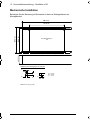
Mechanische Installation
Befestigen Sie die Steuerung mit Schrauben in den vier Montagelöchern am
Montagesockel.
140
(5.51)
129
(5.08)
170 (6.69)
250 (9.84)
40.3
(1.59)
A
A
B
C
A = 4.5 mm
B = 10 mm
C = 11 mm
Alle Abmessungen in
mm
Zeichnungen sind nicht maßstabsgetreu
Detailansicht von Befestigungsloch und Schlitz
Gewicht: Ca. 700 g (1,5 lb)
LT0305A01.book Page 12 Wednesday, June 21, 2017 2:10 PM

Kurzinstallationsanleitung – NextMove e100 13
Anschlüsse
X12 AIN 0-1
& relay
X7 Encoder2
X6 Encoder1
X4 DOUT 8-11
X2 STEP 0-1
5
6
7
2
3
4
1
1
1
X11 DOUT 0-7
1
X10 DIN 0-3
(fast interrupts)
1
X9 DIN 4-11
1
X8 DIN 12-19
1
X13 AOUT 0-3
(demands)
2
X3 STEP 2-3
X5 Encoder0
X1 +24V in
CAN
5
USB
7
2
2
3
4
4
4
Ethernet
Serial
5
6
DIN3
Shield
CREF0
DIN2
Shield
CREF0
DIN1
Shield
CREF0
DIN0
DOUT0
DOUT1
DOUT2
DOUT3
DOUT4
DOUT5
DOUT6
DOUT7
USR V+
USR GND
AIN0+
AIN0-
AGND
AIN1+
AIN1-
Shield
REL COM
REL NC
REL NO
REL COM
1
2
3
4
5
6
7
8
9
10
10
9
8
7
6
5
4
3
2
1
12
11
10
9
8
7
6
5
4
3
2
1
12
11
10
9
8
7
6
5
4
3
2
1
2
1
1
2
3
4
5
6
7
8
9
10
1
2
3
4
5
6
7
8
9
10
1
2
3
4
5
6
7
8
9
10
1
2
3
4
5
6
7
8
9
10
1
2
3
4
5
6
7
8
9
10
11
12
DIN11
DIN10
DIN9
DIN8
DIN7
DIN6
DIN5
DIN4
CREF1
Shield
DIN19
DIN18
DIN17
DIN16
DIN15
DIN14
DIN13
DIN12
CREF2
Shield
CREF2
CREF1
CREF0
USR V+
USR GND
USR V+
DOUT11
DOUT10
DOUT9
DOUT8
Demand0
AGND
Shield
Demand1
AGND
Shield
Demand2
AGND
Shield
Demand3
AGND
Shield
Shield
DIR3+
DIR3-
STEP3+
STEP3-
DGND
Shield
DIR2+
DIR2-
STEP2+
STEP2-
DGND
Shield
DIR3
+5 V
STEP3
(NC)
DGND
Shield
DIR2
+5 V
STEP2
(NC)
DGND
Shield
DIR1+
DIR1-
STEP1+
STEP1-
DGND
Shield
DIR0+
DIR0-
STEP0+
STEP0-
DGND
Shield
DIR1
+5 V
STEP1
(NC)
DGND
Shield
DIR0
+5 V
STEP0
(NC)
DGND
+24 V
0 V
Gegenstecker:
Sauro CTF10008
Sauro CTF12008
Sauro CTF02008
9-poliger Stecker, Typ D
9-polige Buchse, Typ D
RJ45-Stecker
USB-Stecker, Typ B
Das Anzugsdrehmoment für die
Klemmleistenanschlüsse beträgt 0,25 Nm (2,25 lb-in).
Nur 60/75 oder 75 °C Kupferdraht (Cu) verwenden.
(NC) = Nicht angeschlossen
Für Variante
NXE100-16xxSx:
LT0305A01.book Page 13 Wednesday, June 21, 2017 2:10 PM

14 Kurzinstallationsanleitung – NextMove e100
X1 - Stromversorgung
X2, X3 - Schrittmotorregelungsausgänge
X4, X11 - Digitalausgänge
X5, X6, X7 - Encodereingänge
Beschreibung Wert
Stromversorgung
Nenneingangsspannung
Stromaufnahme
24 V DC (±20%)
50 W (2 A bei 24 V)
Beschreibung Einheit NXE100-16xxDx NXE100-16xxSx
Ausgangstyp RS422-
Differenzialausgänge
Darlington-
-schritt (Impuls) und
Richtung
Max. Ausgangsfrequenz 5 MHz 500 kHz
Ausgangsstromstärke 20 mA
(typisch)
50 mA
(max. Ableitung,
pro Ausgang)
Beschreibung Einheit Wert
USR V+ Versorgungsspannung
Nennwert
Minimal
VDC
24
12
Ausgangsstromstärke
Max. Quelle pro Ausgang, ein Ausgang an
Max. Quelle pro Ausgang, alle Ausgänge an
Max. gesamte Ausgangsstromstärke
mA DOUT0-7 DOUT8-11
350 350
62,5 125
500 500
Aktualisierungsintervall (Mint) Sofort
Schaltzeit
Keine Last an Ausgang
Mit 7 mA oder größerer Last
100 ms
10 µs
Beschreibung Einheit Wert
Encodereingang RS422 A/B Differenzial, Z Index
Max. Eingangsfrequenz
Quadratur
MHz
20
Ausgangsstromversorgung zu Encodern
5V (±5%)
500 mA (max. insgesamt für alle
Achsen)
Maximale zulässige Kabellänge 30,5 m (100 ft)
LT0305A01.book Page 14 Wednesday, June 21, 2017 2:10 PM

Kurzinstallationsanleitung – NextMove e100 15
X8, X9, X10 - Digitaleingänge
X12 - Analogeingänge
X12 - Relaisausgang
X13 - Analogausgänge
Beschreibung Einheit Wert
Typ Optisch isoliert
USR V+ Versorgungsspannung
Nennwert
Minimal
VDC
24
12
Eingangsspannung
Aktiv
Inaktiv
VDC
> 12
< 2
Eingangsstromstärke
(Maximal pro Eingang, USR V+ = 24 V)
mA 7
Abtastintervall ms 1
Beschreibung Einheit Wert
Typ Differenzial
Gleichtaktspannungsbereich V DC ±10
Eingangsimpedanz kΩ 120
Maximale Eingangsstromstärke mA 4,9
ADC-Eingangsauflösung Bit 12 (einschl. Vorzeichen-Bit)
Äquivalente Auflösung (±10 V Eingang) mV ±4,9
Abtastintervall µs 500 (beide Eingänge aktiviert)
250 (ein Eingang deaktiviert)
Alle Ausführungen Einheit Alle Ausführungen
Kontaktnennwert (resistiv) 1 A bei 24 V DC
oder
0,25 A bei 30 V AC
Schaltdauer (max.) ms 5
Beschreibung Einheit Wert
Typ Bipolar
Ausgangsspannungsbereich V DC ±10
Ausgangsstromstärke (pro Ausgang) mA 2,5
DAC-Ausgangsauflösung Bit 12
Äquivalente Auflösung mV ±4,9
Aktualisierungsintervall ms 1
LT0305A01.book Page 15 Wednesday, June 21, 2017 2:10 PM

16 Kurzinstallationsanleitung – NextMove e100
Serieller Anschluss
Ethernet-Schnittstelle
CAN-Schnittstelle
Umgebungsdaten
Einheit Alle Ausführungen
Signal RS232 oder RS485/422 nicht isoliert
Bitraten Baud 9600, 19200, 38400,
57600 (Standardwert), 115200
Beschreibung Einheit Wert
Signal
2 verdrillte Zweidrahtleitungen, magnetisch
isoliert
Protokolle Ethernet POWERLINK & TCP/IP
Bitraten MBit/s 100
Beschreibung Einheit Wert
Signal 2-litzig, isoliert
Kanäle 1
Protokoll CANopen
Bitraten kBit/s
10, 20, 50, 100, 125, 250, 500, 1000
Beschreibung Einheit
Betriebstemperaturbereich Min. Max.
°C
°F
0
+32
+45
+113
Maximale Luftfeuchtigkeit % 80% bei Temperaturen bis zu 31 °C (87 °F),
linear abnehmend auf 50% relative
Luftfeuchtigkeit bei 45 °C (113 °F) (nicht
kondensierend)
Maximale Aufstellhöhe
(über NN)
m
ft
2000
6560
Stöße 10 G gemäß
IEC 60068-2-6/27 oder gleichwertige
Vibrationen 1 G, 10-150 Hz gemäß
IEC 60068-2-6/27 oder gleichwertige
LT0305A01.book Page 16 Wednesday, June 21, 2017 2:10 PM

Kurzinstallationsanleitung – NextMove e100 17
24 V DC-Stromversorgung
Der NextMove e100 benötigt für den Betrieb eine 24 V DC-
Stromversorgung, die kontinuierlich 2 A liefern kann. Es ist
empfehlenswert, für den NextMove e100 eine eigene, gesicherte
24 V DC-Stromversorgung mit einer Sicherung mit maximal 4 A
Nennwert vorzusehen. Falls Digitalausgänge verwendet werden,
ist für deren Ansteuerung eine Stromversorgung erforderlich –
siehe Handbuch MN1941WDE.
USB-Kommunikation
Das Modell NextMove e100 kommuniziert mit Hilfe von USB 1.1 mit
dem Host-PC.
Schließen Sie das mitgelieferte USB-Kabel zwischen dem USB-
Anschluss des NextMove e100 (Device) und des Host-PC (USB 1.1
oder USB 2.0) an.
Ethernet-Kommunikation
Der NextMove e100 sendet und empfängt Steuerungswerte mittels
Ethernet POWERLINK.
Schließen Sie ein CAT5 Ethernet-Kabel zwischen dem Steckverbinder
E1 oder E2 des NextMove e100 und einem POWERLINK-kompatiblen
Antrieb wie dem MotiFlex e100 an.
UL-Checkliste
• Der Controller ist in einer klimatisierten Umgebung einzusetzen. Der
Controller muss in Reinluft gemäß der Gehäuseklassifikation
installiert werden. Die Kühlluft muss sauber und frei von korrosiven
Stoffen und elektrisch leitendem Staub sein. Genauere Angaben sind dem
Handbuch MN1941WDE zu entnehmen.
• Die maximale Umgebungstemperatur beträgt 45 °C (113 °F) bei
Nennstromstärke.
• Der Controller muss an einer Stelle installiert werden, an dem der
Verschmutzungsgrad nach UL / IEC 60664-1 nicht mehr als 2 beträgt.
Inbetriebsnahme
Siehe Handbuch MN1941WDE.
LT0305A01.book Page 17 Wednesday, June 21, 2017 2:10 PM

18 Kurzinstallationsanleitung – NextMove e100
LT0305A01.book Page 18 Wednesday, June 21, 2017 2:10 PM

Guía de instalación rápida – NextMove e100 19
Guía de instalación rápida – NextMove e100
Acerca de esta guía
Esta guía contiene información muy básica acerca de la instalación mecánica
y eléctrica de NextMove e100.
Aplicación
Esta guía es válida para todos los modelos de NextMove e100 (Referencia
NXE100...)
Documentos relacionados
Para una lista completa de los documentos relacionados vaya a la cara trasera de la
portada (inglés).
Instrucciones de seguridad
¡ATENCIÓN! Todos los trabajos de instalación y mantenimiento del drive
deben ser realizados, única y exclusivamente, por electricistas cualificados.
No realizar nunca trabajos sobre el drive, el circuito de control de freno, el cable del
motor o el motor mientras esté conectado a la fuente de alimentación. Una vez
desconectado de la fuente de alimentación espere siempre 5 minutos para permitir la
descarga de los condensadores en los circuitos intermedios. Asegúrese siempre,
mediante medición, de que no existe tensión activa.
Un motor de imanes permanentes en rotación puede generar un voltaje peligroso.
Enclave mecánicamente el eje del motor antes de conectarlo al drive. Para trabajar
sobre el sistema del drive, una vez conectado al motor, asegúrese de enclavar
mecánicamente el eje del motor.
LT0305A01.book Page 19 Wednesday, June 21, 2017 2:10 PM

20 Guía de instalación rápida – NextMove e100
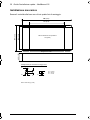
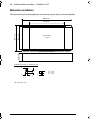
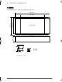
Instalación mecánica
Fijar el controlador a la base de montaje empleando tornillos a través de los cuatro
taladros de montaje.
140
(5.51)
129
(5.08)
170 (6.69)
250 (9.84)
40.3
(1.59)
A
A
B
C
A = 4.5 mm
B = 10 mm
C = 11 mm
Todas las dimensiones indicadas
en mm (pulgadas)
Cotas sin escala
Detalle de ranura y bocallave de montaje
Peso: Aproximadamente 700 g (1,5 libras)
LT0305A01.book Page 20 Wednesday, June 21, 2017 2:10 PM
La pagina sta caricando ...
La pagina sta caricando ...
La pagina sta caricando ...
La pagina sta caricando ...
La pagina sta caricando ...
La pagina sta caricando ...
La pagina sta caricando ...
La pagina sta caricando ...
La pagina sta caricando ...
La pagina sta caricando ...
La pagina sta caricando ...
La pagina sta caricando ...
La pagina sta caricando ...
La pagina sta caricando ...
La pagina sta caricando ...
La pagina sta caricando ...
La pagina sta caricando ...
La pagina sta caricando ...
La pagina sta caricando ...
La pagina sta caricando ...
La pagina sta caricando ...
La pagina sta caricando ...
La pagina sta caricando ...
La pagina sta caricando ...
La pagina sta caricando ...
La pagina sta caricando ...
La pagina sta caricando ...
La pagina sta caricando ...
La pagina sta caricando ...
La pagina sta caricando ...
La pagina sta caricando ...
La pagina sta caricando ...
La pagina sta caricando ...
La pagina sta caricando ...
La pagina sta caricando ...
La pagina sta caricando ...
La pagina sta caricando ...
La pagina sta caricando ...
La pagina sta caricando ...
La pagina sta caricando ...
-
 1
1
-
 2
2
-
 3
3
-
 4
4
-
 5
5
-
 6
6
-
 7
7
-
 8
8
-
 9
9
-
 10
10
-
 11
11
-
 12
12
-
 13
13
-
 14
14
-
 15
15
-
 16
16
-
 17
17
-
 18
18
-
 19
19
-
 20
20
-
 21
21
-
 22
22
-
 23
23
-
 24
24
-
 25
25
-
 26
26
-
 27
27
-
 28
28
-
 29
29
-
 30
30
-
 31
31
-
 32
32
-
 33
33
-
 34
34
-
 35
35
-
 36
36
-
 37
37
-
 38
38
-
 39
39
-
 40
40
-
 41
41
-
 42
42
-
 43
43
-
 44
44
-
 45
45
-
 46
46
-
 47
47
-
 48
48
-
 49
49
-
 50
50
-
 51
51
-
 52
52
-
 53
53
-
 54
54
-
 55
55
-
 56
56
-
 57
57
-
 58
58
-
 59
59
-
 60
60


ABB NextMove e100 Quick Installation Manual
- Tipo
- Quick Installation Manual
in altre lingue
- English: ABB NextMove e100
- français: ABB NextMove e100
- español: ABB NextMove e100
- Deutsch: ABB NextMove e100
- svenska: ABB NextMove e100
Documenti correlati
-
ABB MicroFlex e150 Quick Installation Manual
-
ABB MotiFlex e180 Quick Installation Manual
-
-
-
-
-
-
ABB ACH580-01-034A-4 Quick Installation And Start-Up Manual
-
