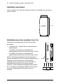
ABB MicroFlex e150 Quick Installation Manual
- Tipo
- Quick Installation Manual

ABB motion control
Quick installation guide
MicroFlex e150
English . . . . . . . . . . . . . . . . . . . . . . . . . 3
Deutsch. . . . . . . . . . . . . . . . . . . . . . . . 13
Español. . . . . . . . . . . . . . . . . . . . . . . . 23
Français . . . . . . . . . . . . . . . . . . . . . . . 33
Italiano . . . . . . . . . . . . . . . . . . . . . . . . 43
Svenska . . . . . . . . . . . . . . . . . . . . . . . 53
中文. . . . . . . . . . . . . . . . . . . . . . . . . . . 63
LT0307A02
Effective: 2015-03-01
2015 ABB Oy. All rights reserved.

List of related manuals
You can find manuals and other product documents in PDF format on the Internet. See section Document
library on the Internet on the inside of the back cover. For manuals not available in the Document library,
contact your local ABB representative.
Drive hardware manuals and guides Code (English)
MicroFlex e150 Servo Drive MN1961WEN
Mint Basic Programming MN1955WEN

Quick Installation Guide – MicroFlex e150 3
Quick Installation Guide – MicroFlex e150
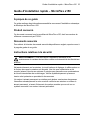
About this guide
This guide contains very basic information about the mechanical and electrical
installation of the MicroFlex e150.
Applicability
Applies to all models of MicroFlex e150, part numbers beginning E152A...
Related documents
For a list of related documents in English, see the inside of the front cover.
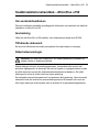
Safety instructions
WARNING! All electrical installation and maintenance work on the drive should
be carried out by qualified electricians only.
Never work on the drive, the braking chopper circuit, the motor cable or the motor
when input power is applied to the drive. After disconnecting the input power, always
wait for 5 minutes to let the intermediate circuit capacitors discharge. Always ensure
by measuring that no voltage is actually present.
A rotating permanent magnet motor can generate a dangerous voltage. Lock the
motor shaft mechanically before connecting a permanent magnet motor to the drive,
and before doing any work on a drive system connected to a permanent magnet
motor.

4 Quick Installation Guide – MicroFlex e150
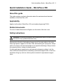
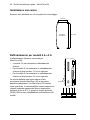
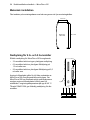
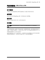
Mechanical installation
Fasten the drive to the mounting base using screws through the four mounting holes.
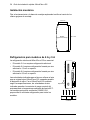
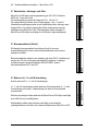
Cooling for 6 A and 9 A models
Effective cooling for the MicroFlex e150 is essential:
• The 3 A model requires no additional cooling.
• The 6 A model requires additional forced air cooling at
1.0 m/s or greater.
• The 9 A model requires additional forced air cooling at
2.5 m/s or greater.
Quoted air velocities are for air originating from below the
MicroFlex e150, passing parallel to the heat sink. With
MicroFlex e150 mounted as specified, quoted air
velocities allow full drive rated current at ambient
temperatures up to 45 °C. Optional fan tray FAN001-024
provides sufficient cooling for all models.
63.5 mm
167.7 mm
Mounting
hole centres
Heat sink
Fan

Quick Installation Guide – MicroFlex e150 5
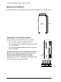
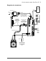
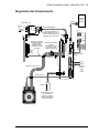
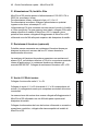
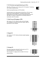
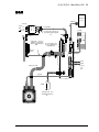
Connection diagram
L1
L2
L3
L1
L2
L3
USB
+24V 0V
L1
L2
L3
PE
Ethernet
Ferrite
STO1
STO2
19
18
9
Safe
Torque
Off
inputs
Control circuit
supply.Use twisted
pair cable with a
ferrite sleeve.
Motor
Optional
brake
resistor.
Motor power U V W
Brake
Motor feedback
Shielded twisted pair,
clamped to metal
backplane near drive
using conductive
shield earth/ground
clamp.
Star
point
AC power in
From
fuses
Filter
AC power
Connect motor power
cable shield to metal
backplane using
conductive shield
clamp.
USB
communication
Host PC
Fuse
Connect AC power cable
shield to metal backplane
using conductive shield
clamp.
EtherCAT
master
device

6 Quick Installation Guide – MicroFlex e150
AC power, fuses and filter
MicroFlex e150 can accept supply voltages of 105-250 V AC 50/60 Hz,
1-phase or 3-phase.
For three phase supplies, connect phases to L1, L2 and L3.
For single phase supplies, connect supply to any two line inputs, for
example L1 and L2.
The AC supply must incorporate a circuit breaker (or fuse) and the
specified filter. For ideal earthing, mount filter on the same metal surface
as MicroFlex e150. Protective earth must be connected to the
MicroFlex e150 case using an M4 screw in the top of the metal heat
sink.
Brake resistor (optional)
A suitable brake resistor may be required to dissipate excess power
from the internal DC bus during motor deceleration.
The brake resistor must have a resistance of at least 39 Ω, inductance
of less than 100 μH, and a power rating suitable for the application.
Suitable resistors are listed in manual MN1961WEN. Connect the brake
resistor to R1 and R2.
Motor U V W outputs
Connect the motor to the U, V and W outputs.
The U, V and W outputs must be connected to their corresponding U, V
or W terminal on the motor. Mis-connection may result in uncontrolled
motor movement.
Motor earth should be connected to the MicroFlex e150 case using an
M4 screw in the top of the metal heat sink.
The motor cable shield should be connected using a conductive
earth/ground clamp, attached to the same metal surface as the
MicroFlex e150.
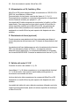
L1
L2
L3
X1
R1
R2
X1
U
V
W
X1

Quick Installation Guide – MicroFlex e150 7
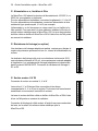
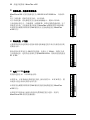
24 V DC control supply and filter
MicroFlex e150 requires a 24 V DC (20-30 V DC) 1 A supply to power
the control electronics.
Connect the control supply at connector X2.
A fused DC supply should be provided for the MicroFlex e150. If other
devices are to be powered from the same 24 V supply, a filter (catalog
number FI0014A00) should be installed to isolate the MicroFlex e150
from the rest of the system. Alternatively, a ferrite sleeve may be
attached to the supply cable near connector X2.
Safe Torque Off (STO) inputs
24 V DC (12-30 V DC) must be applied to both STO inputs
to allow the drive to operate. SREF is common to both
inputs.
Digital I/O
24 V DC (12-30 V DC) general purpose digital inputs and
outputs.
Analog I/O
An analog input can be used to receive a ±10 V demand
signal from a motion controller.
The ±10 V analog output can be used to control external
devices.
0V
24V
X2
X3
STO1
STO2SREF
SREF
X3
Status+
DOUT2+DOUT2-
Status-
DOUT1+DOUT1-
DIN2+DIN2-
DIN3+DIN3-
DIN1+DIN1-
DIN0+DIN0-
X4
AIN1-
AIN0-AIN0+
AIN1+
ShieldShield
AGNDAOUT0

8 Quick Installation Guide – MicroFlex e150
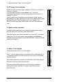
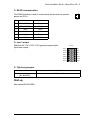
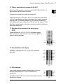
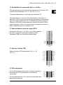
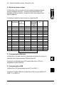
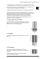
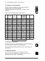
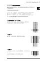
Motor feedback input
The MicroFlex e150 can operate with incremental, BiSS, SSI,
SmartAbs, EnDat, or SinCos encoder feedback devices. The device
type is configured in Mint WorkBench.
Connect the motor feedback signal to connector X8.
Ethernet communication
The MicroFlex e150 can receive a demand signal and send feedback
over the Ethernet based EtherCAT connection.
Connect a CAT5 Ethernet cable between the MicroFlex e150 and the
EtherCAT master device.
USB communication
The MicroFlex e150 communicates with the host PC using USB 1.1
communication.
Connect the USB cable between the MicroFlex e150 and the host PC's
USB port (USB 1.1 or USB 2.0).
Pin Increment.
encoder
BiSS, SSI
or
EnDat 2.2
Smart Abs
Extra
incremental
encoder
EnDat
2.1
SinCos
1 CHA+ Data+ Data+ (NC) Data+ (NC)
2 CHB+ Clock+ (NC) (NC) Clock+ (NC)
3 CHZ+ (NC) (NC) (NC) (NC) (NC)
4 (NC) (NC) (NC) (NC) (NC) (NC)
5 Hall U- (NC) (NC) CHA- Sin- Sin-
6 Hall U+ (NC) (NC) CHA+ Sin+ Sin+
7 Hall V- (NC) (NC) CHB- Cos- Cos-
8 Hall V+ (NC) (NC) CHB+ Cos+ Cos+
9 CHA- Data- Data- (NC) Data- (NC)
10 CHB- Clock- (NC) (NC) Clock- (NC)
11 CHZ- (NC) (NC) (NC) (NC) (NC)
12 +5 V out +5 V out +5 V out +5 V out +5 V out +5 V out
13 DGND DGND DGND DGND DGND DGND
14 Hall W- (NC) (NC) CHZ- (NC) (NC)
15 Hall W+ (NC) (NC) CHZ+ (NC) (NC)
See manual MN1961WEN
X8
1
8
9
15

Quick Installation Guide – MicroFlex e150 9
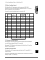
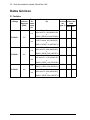
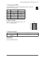
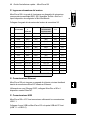
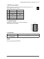
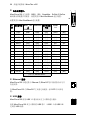
RS485 communication
The RS485 interface is used to connect serial devices such as operator
panels and PLCs.
Input / output
Additional 24 V DC (12-30 V DC) general purpose digital
inputs and outputs.
Tightening torques
Start-up
See manual MN1961WEN.
Pin 2-wire 4-wire
1 TXA(+) / RXA(+) TXA(+)
2 TXB(-) / RXB(-) TXB(-)
3GND GND
4 7 V out 7 V out
5 (NC) RXA(+)
6 (NC) RXB(-)
N·m (lbf·in)
Terminal block connections
(X1, X2, OPT1)
0.5 - 0.6 (4.4 - 5.3)
X6
1
OPT1
DIN4
DIN5
CREF1
Shield
DIN6
DIN8
DIN7
DIN9
CREF0
USRV+0
DOUT3
DOUT5
DOUT4
DOUT6

10 Quick Installation Guide – MicroFlex e150
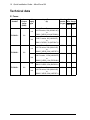
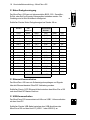
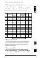
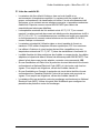
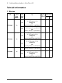
Technical data
Fuses
Catalog
Number
Continuous
Output
Amps
(RMS)
AC
supply
type
Input Fuse
(A)
Circuit
breaker
(C-type)
Minimum
Wire Gauge
AWG mm
2
E152A03... 3A
1Φ
Ferraz Shawmut:
6x32 FA series, 10A (W084314P)
or
BS88 2.5 URGS 10A (N076648J)
10 A 14 2
3Φ
Ferraz Shawmut:
6x32 FA series, 8A (V084313P)
or
BS88 2.5 URGS, 7A (M076647J)
8A 14 2
E152A06... 6A
1Φ
Ferraz Shawmut:
6x32 FA series, 20A (A084318P)
or
BS88 2.5 URGS, 20A (L097507J)
20 A 14 2
3Φ
Ferraz Shawmut:
6x32 FA series, 12.5A (X084315P)
or
BS88 2.5 URGS, 12A (P076649J)
12.5 A 14 2
E152A09... 9A
1Φ
Ferraz Shawmut:
BS88 2.5 URGS, 25A (R076651J)
25 A 14 2.5
3Φ
Ferraz Shawmut:
6x32 FA series, 20A (A084318P)
or
BS88 2.5 URGS, 20A (L097507J)
20 A 14 2

Quick Installation Guide – MicroFlex e150 11
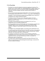
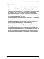
UL checklist
• The drive is to be used in a heated, indoor controlled environment. The drive must
be installed in clean air according to enclosure classification. Cooling air must be
clean, free from corrosive materials and electrically conductive dust. See manual
MN1961WEN for detailed specifications.
• The maximum ambient air temperature is 45 °C (113 °F) at rated current. The
current is derated for 45 to 55 °C (113 to 131 °F). Fan cooling is required to allow
full rated current on the 6 A and 9 A models, as explained in this document.
• The drive is suitable for use in a circuit capable of delivering not more than 5,000
rms symmetrical amperes, 230 V maximum.
• The cables located within the motor circuit must be rated for at least 75 °C
(167 °F) in UL-compliant installations.
• The input cable must be protected with fuses or circuit breakers. Suitable types
are listed in the complete product manual, MN1961WEN. For suitable circuit
breakers, contact your local ABB representative.
• For installation in the United States, branch circuit protection must be provided in
accordance with the National Electrical Code (NEC) and any applicable local
codes. To fulfill this requirement, use the UL classified fuses.
• For installation in Canada, branch circuit protection must be provided in
accordance with Canadian Electrical Code and any applicable provincial codes.
To fulfill this requirement, use the UL classified fuses.
• The drive provides overload protection in accordance with the National Electrical
Code (NEC). Use the Mint WorkBench software to configure overload protection
settings.

12 Quick Installation Guide – MicroFlex e150

Kurzinstallationsanleitung – MicroFlex e150 13
Kurzinstallationsanleitung – MicroFlex e150
Über diese Anleitung
Diese Anleitung enthält sehr grundlegende Informationen zur mechanischen und
elektrischen Installation des MicroFlex e150.
Geltungsbereich
Gilt für alle MicroFlex e150-Modelle, deren Teilenummern mit E152A... beginnen.
Zugehörige Dokumente
Eine Liste der zugehörigen Dokumente in Englisch ist auf der Rückseite des
Deckblatts dieses Dokuments zu finden.
Sicherheitsanweisungen
WARNUNG! Alle elektrischen Installations- und Wartungsarbeiten am Antrieb
sollten ausschließlich von qualifizierten Elektrofachkräften durchgeführt
werden.
Arbeiten Sie keinesfalls am Antrieb, dem Chopperbremsschaltkreis, dem Motorkabel
oder dem Motor, wenn die Stromversorgung am Antrieb anliegt. Nach Unterbrechung
der Stromversorgung warten Sie 5 Minuten, damit sich die zwischengeschalteten
Kondensatoren entladen können. Stellen Sie durch Messen sicher, dass keine
Spannung mehr anliegt.
Ein sich drehender Motor mit Permanentmagneten kann gefährliche Spannung
erzeugen. Verriegeln Sie die Motorwelle mechanisch, bevor Sie einen Motor mit
Permanentmagneten an den Antrieb anschließen und bevor Sie Arbeiten an einem
Antriebssystem mit angeschlossenem Motor mit Permanentmagneten ausführen.

14 Kurzinstallationsanleitung – MicroFlex e150
Mechanische Installation
Befestigen Sie den Antrieb mit Schrauben in den vier Montagelöchern am
Montagesockel.
Kühlung für die Modelle mit 6 A und 9 A
Effektive Kühlung ist für den MicroFlex e150 von
entscheidender Bedeutung:
• Das Modell mit 3 A benötigt keine zusätzliche
Kühlung.
• Das Modell mit 6 A erfordert zusätzliche Luftkühlung
mit Zwangsumwälzung von mindestens 1,0 m/s.
• Das Modell mit 9 A erfordert zusätzliche Luftkühlung
mit Zwangsumwälzung von mindestens 2,5 m/s.
Die angegebenen Luftgeschwindigkeiten gelten für eine
Luftversorgung unterhalb des MicroFlex e150, die parallel
zum Kühlkörper geblasen wird. Wenn das Modell
MicroFlex e150 vorschriftsmäßig montiert ist,
ermöglichen die angegebenen Luftgeschwindigkeiten die
Nennstromstärke für den Antrieb bei
Umgebungstemperaturen von bis zu 45°C.Ein optionales
Ventilatormodul FAN001-024 sorgt für ausreichende
Kühlung aller Varianten.
63.5 mm
167.7 mm
Befestigung
Lochmitte
Kühlkörper
Lüfter

Kurzinstallationsanleitung – MicroFlex e150 15
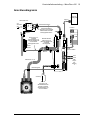
Anschlussdiagramm
L1
L2
L3
L1
L2
L3
USB
+24V 0V
L1
L2
L3
PE
Ethernet
Ferrite
STO1
STO2
19
18
9
Safe
Torque
Off-
Eingäng
e
Versorgung der
Steuerelektronik des
Antriebs. Verdrillte
Zweidrahtleitung mit
einer Ferrithülse
Motor
Optional
er
Bremswi
Motorstrom U V W
Bremse
Motordrehgeber
Abschirmung von
verdrillter
Zweidrahtleitung mit
leitender Metallschelle
auf der Metall-
Montageplatte in der
Sternpun
kt
Wechselstromeingan
Von
Sicherun
gen
Filter
Wechselstromve
Motorstromkabel-
Abschirmung mit
leitender Metallschelle
auf Metall-
Montageplatte
USB-
Kommunikation
Host-PC
Sicherung
Wechselstromkabel-
Abschirmung mit leitender
Metallschelle auf Metall-
Montageplatte fixieren.
EtherCAT-
Mastergerät

16 Kurzinstallationsanleitung – MicroFlex e150
Wechselstrom, Sicherungen und Filter
Der MicroFlex e100 kann Versorgungsspannungen von 105-250 V AC,
50/60 Hz, 1-phasig oder 3-phasig, aufnehmen.
Bei dreiphasiger Versorgung müssen die Phasen an L1, L2 und L3
angeschlossen werden.
Bei einphasiger Versorgung muss die Versorgung an beliebige zwei
Eingangsleiter angeschlossen werden, beispielsweise L1 und L2.
Die Wechselstromversorgung muss über einen Trennschalter (oder
eine Sicherung) und den vorgeschriebenen Filter verfügen. Die beste
Erdung erfolgt, wenn der Filter auf derselben Metallfläche wie der
MicroFlex e150 montiert wird. Die Schutzerde muss mit einer M4-
Schraube im oberen Teil des Kühlkörpers an das Gehäuse des
MicroFlex e150 angeschlossen werden.
Bremswiderstand (optional)
Es ist eventuell ein geeigneter Bremswiderstand erforderlich, um bei der
Motorabbremsung überschüssige Leistung aus dem internen
Gleichstrombus abzuleiten.
Der Bremswiderstand muss einen Widerstand von mindestens 39Ω,
eine Induktanz von weniger als 100μH und eine für die Anwendung
geeignete Nennleistung haben. Geeignete Widerstände sind im
Handbuch MN1961WDE aufgeführt. Schließen Sie den
Bremswiderstand an R1 und R2 an.
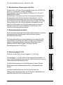
Motorausgänge U V W
Schließen Sie den Motor an die Ausgänge U, V und W an.
Die Ausgänge U, V und W müssen an die zugehörigen Kontakte U, V
oder W am Motor angeschlossen werden. Falscher Anschluss kann zu
unkontrollierter Motorbewegung führen.
Die Motorerdung muss mit einer M4-Schraube im oberen Teil des
Kühlkörpers an das Gehäuse des MicroFlex e150 angeschlossen
werden.
Die Motor-Kabelabschirmung sollte über eine leitende Erd-
/Masseschelle hergestellt werden, die an die gleiche Metallfläche wie
das Modell MicroFlex e150 angeschlossen ist.
L1
L2
L3
X1
R1
R2
X1
U
V
W
X1

Kurzinstallationsanleitung – MicroFlex e150 17
24 V DC-Logikversorgung und Filter
Der MicroFlex e150 benötigt zum Betrieb der Regelelektronik eine 24 V
DC-Stromversorgung (20-30 VDC) mit 1 A.
Schließen Sie die Logikversorgung an Stecker X2 an.
Für den MicroFlex e150 sollte eine gesicherte Gleichstromversorgung
vorgesehen werden. Wenn die 24-VDC-Stromversorgung auch noch
andere Geräte versorgen soll, muss ein Filter (Katalognummer
FI0014A00) eingebaut werden, um den MicroFlex e150 vom Rest des
Systems zu isolieren. Als Alternative kann in der Nähe des Steckers X2
eine Ferrithülse am Versorgungskabel angebracht werden.
Safe Torque Off-Eingänge (STO)
24 V DC (12-30 V DC) müssen an beiden STO-Eingängen
anliegen, damit der Antrieb in Betrieb gehen kann. SREF
dient beiden Eingängen.
Digital-E/A
Allzweck-Digitalein- und -ausgänge mit 24 V DC (12-
30 V DC).
Analog-E/A
Ein Analogeingang kann ein ±10 V-Sollwertsignal von
einem Motion Controller empfangen.
Der ±10 V-Analogausgang kann zur Steuerung externer
Geräte eingesetzt werden.
0V
24V
X2
X3
STO1
STO2SREF
SREF
X3
Status+
DOUT2+DOUT2-
Status-
DOUT1+DOUT1-
DIN2+DIN2-
DIN3+DIN3-
DIN1+DIN1-
DIN0+DIN0-
X4
AIN1-
AIN0-AIN0+
AIN1+
ShieldShield
AGNDAOUT0

18 Kurzinstallationsanleitung – MicroFlex e150
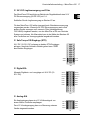
Motor-Drehgebereingang
Der MicroFlex e150 kann mit inkrementellen BiSS-, SSI-, SmartAbs-,
EnDat- oder SinCos-Encoder-Gebergeräten betrieben werden. Der
Gerätetyp wird in Mint WorkBench konfiguriert.
Schließen Sie das Motor-Drehgebersignal an Stecker X8 an.
Ethernet-Kommunikation
Der MicroFlex e150 kann ein Sollwertsignal empfangen und Signale
über die Ethernet-basierte EtherCAT-Verbindung senden.
Schließen Sie ein CAT5 Ethernet-Kabel zwischen dem MicroFlex e150
und dem EtherCAT-Master-Gerät an.
USB-Kommunikation
Der MicroFlex e150 kommuniziert mit Hilfe von USB1.1-Kommunikation
mit dem Host-PC.
Schließen Sie das USB-Kabel zwischen dem USB-Anschluss des
MicroFlex e150 und des Host-PC (USB 1.1 oder USB 2.0) an.
Pin Inkrementeller
Encoder
BiSS, SSI
oder
EnDat 2.2
Smart Abs Zusätzl.
inkrementeller
Encoder
EnDat 2.1 SinCos
1 CHA+ Data+ Data+ (NC) Data+ (NC)
2 CHB+ Clock+ (NC) (NC) Clock+ (NC)
3 CHZ+ (NC) (NC) (NC) (NC) (NC)
4 (NC) (NC) (NC) (NC) (NC) (NC)
5 Hall U- (NC) (NC) CHA- Sin- Sin-
6 Hall U+ (NC) (NC) CHA+ Sin+ Sin+
7 Hall V- (NC) (NC) CHB- Cos- Cos-
8 Hall V+ (NC) (NC) CHB+ Cos+ Cos+
9 CHA- Data- Data- (NC) Data- (NC)
10 CHB- Clock- (NC) (NC) Clock- (NC)
11 CHZ- (NC) (NC) (NC) (NC) (NC)
12 +5 V out +5 V out +5 V out +5 V out +5 V out +5 V out
13 DGND DGND DGND DGND DGND DGND
14 Hall W- (NC) (NC) CHZ- (NC) (NC)
15 Hall W+ (NC) (NC) CHZ+ (NC) (NC)
Siehe Handbuch MN1961WDE
X8
1
8
9
15

Kurzinstallationsanleitung – MicroFlex e150 19
RS485-Kommunikation
Der RS485-Anschluss wird für den Anschluss eines seriellen Geräts wie
etwa Bedienfeldleisten und SPS verwendet.
Eingang / Ausgang)
Zusätzliche Allzweck-Digitalein- und -ausgänge mit
24 V DC (12-30 V DC).
Anzugsdrehmomente
Inbetriebnahme
Siehe Handbuch MN1961WDE.
Pin 2-litzig 4-litzig
1 TXA(+) / RXA(+) TXA(+)
2 TXB(-) / RXB(-) TXB(-)
3GND GND
4 7 V out 7 V out
5 (NC) RXA(+)
6 (NC) RXB(-)
Nm (lbf·in)
Klemmleistenanschlüsse
(X1, X2, OPT1)
0,5 - 0,6 (4,4 - 5,3)
X6
1
OPT1
DIN4
DIN5
CREF1
Shield
DIN6
DIN8
DIN7
DIN9
CREF0
USRV+0
DOUT3
DOUT5
DOUT4
DOUT6

20 Kurzinstallationsanleitung – MicroFlex e150
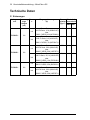
Technische Daten
Sicherungen
Katalognum
mer
Dauerausg
angs
Ampere
(eff)
Phase
n
Eingangssicherung
(A)
Trenn-
schalter
(Typ C)
Mindestleite
rquerschnitt
AWG mm
2
E152A03... 3A
1Φ
Ferraz Shawmut:
6x32 FA Serie, 10 A (W084314P)
oder
BS88 2.5 URGS 10A (N076648J)
10 A 14 2
3Φ
Ferraz Shawmut:
6x32 FA Serie, 8 A (V084313P)
oder
BS88 2.5 URGS, 7A (M076647J)
8A 14 2
E152A06... 6A
1Φ
Ferraz Shawmut:
6x32 FA Serie, 20 A (A084318P)
oder
BS88 2.5 URGS, 20A (L097507J)
20 A 14 2
3Φ
Ferraz Shawmut:
6x32 FA Serie, 12,5 A (X084315P)
oder
BS88 2.5 URGS, 12A (P076649J)
12,5 A 14 2
E152A09... 9A
1Φ
Ferraz Shawmut:
BS88 2.5 URGS, 25A (R076651J)
25 A 14 2,5
3Φ
Ferraz Shawmut:
6x32 FA Serie, 20 A (A084318P)
oder
BS88 2.5 URGS, 20A (L097507J)
20 A 14 2
La pagina si sta caricando...
La pagina si sta caricando...
La pagina si sta caricando...
La pagina si sta caricando...
La pagina si sta caricando...
La pagina si sta caricando...
La pagina si sta caricando...
La pagina si sta caricando...
La pagina si sta caricando...
La pagina si sta caricando...
La pagina si sta caricando...
La pagina si sta caricando...
La pagina si sta caricando...
La pagina si sta caricando...
La pagina si sta caricando...
La pagina si sta caricando...
La pagina si sta caricando...
La pagina si sta caricando...
La pagina si sta caricando...
La pagina si sta caricando...
La pagina si sta caricando...
La pagina si sta caricando...
La pagina si sta caricando...
La pagina si sta caricando...
La pagina si sta caricando...
La pagina si sta caricando...
La pagina si sta caricando...
La pagina si sta caricando...
La pagina si sta caricando...
La pagina si sta caricando...
La pagina si sta caricando...
La pagina si sta caricando...
La pagina si sta caricando...
La pagina si sta caricando...
La pagina si sta caricando...
La pagina si sta caricando...
La pagina si sta caricando...
La pagina si sta caricando...
La pagina si sta caricando...
La pagina si sta caricando...
La pagina si sta caricando...
La pagina si sta caricando...
La pagina si sta caricando...
La pagina si sta caricando...
La pagina si sta caricando...
La pagina si sta caricando...
La pagina si sta caricando...
La pagina si sta caricando...
La pagina si sta caricando...
La pagina si sta caricando...
La pagina si sta caricando...
La pagina si sta caricando...
La pagina si sta caricando...
La pagina si sta caricando...
-
 1
1
-
 2
2
-
 3
3
-
 4
4
-
 5
5
-
 6
6
-
 7
7
-
 8
8
-
 9
9
-
 10
10
-
 11
11
-
 12
12
-
 13
13
-
 14
14
-
 15
15
-
 16
16
-
 17
17
-
 18
18
-
 19
19
-
 20
20
-
 21
21
-
 22
22
-
 23
23
-
 24
24
-
 25
25
-
 26
26
-
 27
27
-
 28
28
-
 29
29
-
 30
30
-
 31
31
-
 32
32
-
 33
33
-
 34
34
-
 35
35
-
 36
36
-
 37
37
-
 38
38
-
 39
39
-
 40
40
-
 41
41
-
 42
42
-
 43
43
-
 44
44
-
 45
45
-
 46
46
-
 47
47
-
 48
48
-
 49
49
-
 50
50
-
 51
51
-
 52
52
-
 53
53
-
 54
54
-
 55
55
-
 56
56
-
 57
57
-
 58
58
-
 59
59
-
 60
60
-
 61
61
-
 62
62
-
 63
63
-
 64
64
-
 65
65
-
 66
66
-
 67
67
-
 68
68
-
 69
69
-
 70
70
-
 71
71
-
 72
72
-
 73
73
-
 74
74


ABB MicroFlex e150 Quick Installation Manual
- Tipo
- Quick Installation Manual
in altre lingue
- English: ABB MicroFlex e150
- français: ABB MicroFlex e150
- español: ABB MicroFlex e150
- Deutsch: ABB MicroFlex e150
- svenska: ABB MicroFlex e150
Documenti correlati
Altri documenti
-
 Baldor-Reliance Metric-E Motors Manuale del proprietario
-
Baumer MHAD 50 - HDmag Installation and Operating Instructions
-
Yamaha CRX-E150 Manuale del proprietario
-
Sony VPL-ES2 Manuale del proprietario
-
CARLO GAVAZZI DUB72D724EX Guida d'installazione
-
Shure MX400D Manuale utente
-
-
-
Eurotherm tis Guida utente
-
