Electrolux EGM626K Manuale utente
- Categoria
- Piani cottura
- Tipo
- Manuale utente
Questo manuale è adatto anche per

Gas hobs
Mod. EGM 626 - EGM 636
INSTRINSTR
INSTRINSTR
INSTR
UCTION BOOKLETUCTION BOOKLET
UCTION BOOKLETUCTION BOOKLET
UCTION BOOKLET
Please read this instruction booklet before using the appliance
35679-2502
HR - SI - PT

2
About Installation, Cleaning and Manteinance
• It is mandatory that all operations required for the
installation are carried out by a qualified or competent
person, in accordance with existing rules and regulations.
• Disconnect the appliance from the electrical supply, before
carrying out any cleaning or manteinance work.
• Ensure a good ventilation around the appliance. A poor air
supply could cause lack of oxygen.
• Ensure that the gas supply complies with the gas type
stated on the identification label, placed near the gas
supply pipe.
• Using a gas cooking appliance will produce heat and
moisture in the room which it has been installed in.
Ensure a continuous air supply, keeping the air vents in
good conditions or installing a cooker hood with
discharge tube.
• In case of intensive or long time use of the appliance,
make the ventilation more efficient, by opening a
window or increasing the electric exhaust fan power.
• Once you removed all packaging from the appliance,
ensure that it is not damaged and the electric cable is in
perfect conditions. Otherwise, contact your dealer before
proceeding with the installation.
• The manufacturer disclaims any responsability should
all the safety measures not be carried out.
• Under no circumstances should you attempt to repair the
appliance yourself. Repairs carried out by unexperienced
persons may cause injury or serious malfunctioning.
Refer to your local Service Centre. Always insist on
genuine spare parts.
Child Safety
• This appliance has been designed to be operated by
adults and children under supervision. Young children
MUST NOT be allowed to tamper with the controls or play
near or with the oven.
• Accessible parts of this appliance may become hot
when it is in use. Children should be KEPT AWAY until it has
cooled.
During Operation
• It is most important that this instruction book should be
retained with the appliance for future reference. Should
the appliance be sold or transferred, always ensure that
the book is left with the appliance in order that the new
owner can get to know the functions of the appliance and
the relevant warnings.
• This appliance has been designed for non professional
purpose in private houses only. It is meant to cook edible
foodstuff only and
MUST NOT be used for any other purposes.
• It is dangerous to alter the specification in any way.
• For hygiene and safety reasons, this appliance should
be kept clean at all times. A build-up of fats or other
foodstuff could result in a fire.
• Under no circumstances should you attempt to repair the
appliance yourself. Repairs carried out by unexperienced
persons may cause injury or serious malfunctioning.
English
These warnings are provided in the interest of safety. You MUST read them carefully before
installing or using the appliance.
Important Safety Information
Refer to your local Service Centre. Always insist on
genuine spare parts.
• Ensure that all control knobs are in the OFF position when
not in use.
• Should you connect any electrical tool to a plug near this
cooking appliance, ensure that electric cables are not in
contact with it and keep them far enough from the heated
parts of this appliance.
• If the appliance is out of order, disconnect it from the
electric supply.
Ceramic hob
• The residual heat indicator comes on when the cooking
zone is switched on. Children should be kept away until
it switches off.
• Never use the ceramic hob as a working space. Do not
store things on the ceramic hob.
• Never use plastic or aluminium foil dishes on the
ceramic hob, as they could melt on the hob, thus
damaging it. Anyway,If anything of this nature accidentally
comes into contact with the ceramic surface it must be
scraped off immediately while stlll hot and wiped away
to avoid damage to the surface. In the same way, remove
sugar or food residues with hich sugar content, which
may have split from saucepans by using a scraper for
ceramic hobs.
• Unstable or misshapen pans should not be used on
the ceramic hob as unstable pans can cause an accident
by tipping or spillage.
• The ceramic hob is shockproof, but not unbreakable!
Hard or pointed objects falling from a height can damage
the hob. If scratches or cracks are noticed, disconnect
the appliance from the electrical supply and call you
nearest Service Force Centre.
• Never use scratching sponges, abrasive products or
chemically powerful detergents. Use only cleaning
agents specific for ceramic hobs.
Environmental Information
• After installation, please dispose of the packaging with
due regard to safety and the environment.
• When disposing of an old appliance, make it unusable, by
cutting off the cable.
• Il simbolo sul prodotto o sulla confezione indica
che il prodotto non deve essere considerato come un
normale rifiuto domestico, ma deve essere portato nel
punto di raccolta appropriato per il riciclaggio di
apparecchiature elettriche ed elettroniche. Provveden-
do a smaltire questo prodotto in modo appropriato, si
contribuisce a evitare potenziali conseguenze negative
per l’ambiente e per la salute, che potrebbero derivare
da uno smaltimento inadeguato del prodotto. Per infor-
mazioni più dettagliate sul riciclaggio di questo prodot-
to, contattare l’ufficio comunale, il servizio locale di
smaltimento rifiuti o il negozio in cui è stato acquistato
il prodotto.

3
These instructions are only for the countries
stated by the symbol printed on the front cover
of this instruction book.
MANUFACTURER:
ELECTROLUX HOME PRODUCTS ITALY S.p.A.
Viale Bologna 298 - 47100 FORLI’ (Italy)
Contents
For the User
Important Safety Information 2
Instruction for the User 4
Cleaning and Maintenance 6
For the Installer
Technical Data 7
Instruction for the Installer 7
Electrical Connection 8
Adaptation to different types of gas 9
Building In 10
Possibilities for insertion 11
This appliance complies with the following
E.E.C. Directives:
- 73/23 - 90/683 (Low Voltage Directive);
- 89/336
(Electromagnetical Compatibility Directive);
- 93/68 (General Directives)
and subsequent modifications.
The following symbols will be found in the text to
guide you throughout the Instructions:
Safety Instructions
Step by step instructions for an operation
Hints and Tips
Environmental information
Guide to Use the instructions

4
Once the hob has been installed, it is
important to remove any protective materials,
which were put on in the factory.
Hob burners control knobs
The hob burners control knobs are situated on the hob
right hand side. The symbols on the knobs mean that:
there is no gas supply
there is maximum gas supply
there is minimum gas supply
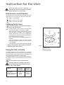
Lighting the burners
For easier lighting, proceed before putting a
pan on the pan support.
To light a burner, push in the relevant knob and
turn it anticlockwise to "maximum position".
After lighting the flame, keep the knob pushed
down for about 5 seconds. This will allow the
"thermocouple" (Fig. 1, lett. C) to be heated and
the safety device to be switched off, otherwise the
gas supply would be interrupted.
Then, check the flame is regular and adjust it as
required.
If you cannot light the flame even after several
attempts, check the "cap" (Fig. 1, lett. A) is in the
correct position.
To put the flame out, turn the knob to the symbol .
• Always turn the flame down or put it out before
taking the pans off the burner.
Burner minimum maximum
diameter diameter
Big (rapid) 160 mm 260 mm
Medium (semirapid) 120 mm 220 mm
Small (Auxiliary) 80 mm 160 mm
Instruction for the User
A - Burner cap
B - Ignition candle
C - Thermocouple
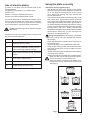
Using the hob correctly
To ensure maximum burner efficiency, it is strongly
recommended that you use only pots and pans with a
bottom fitting the size of the burner used, so that flame will
not spread beyond the bottom of the vessel.
It is also advisable, as soon as a liquid starts boiling, to
turn down the flame so that it will barely keep the liquid
simmering.
Use only pans or pots with flat bottom.
Carefully supervise cookings with fats or
oil, since these types of foodstuff can result
in a fire, if over-heated.
Fig. 1
FO 2295

5
Use of electric plates
To switch on the plate, turn the relevant knob to the
required position.
The plates are regulated by a 7 position switch:
Position 0: off
Position 1: minimum disbursement of heat
Position 6: maximum disbursement of heat
The hob is fitted with a residual heat indicator which
comes on to indicate that the cooking zone is switched
on.The indicator will remain on even after the cooking
zone is switched off, until the hob has cooled down.
Children should be kept away until this indicator
switches off.
Position
1 Melting butter, chocolate,
2 Simmering vegetables, or fish in its own
juice, simmering potatoes or soups
3 Boiling large quantities of food, stews and
soups
4 Slow frying, making a roux
5 Fast frying of meat or fish
6 Rapid heating up of fat or water
Suggestions for the correct setting of the cooking zones
are given in the following table.
Using the plate correctly
Saucepans and frying pans (Fig.2)
- Saucepans and frying pans should not be smaller
than the cooking zone, and preferably not more than
10-15 mm larger than the diameter of the cooking
zone. Always use cooking and frying utensils with
smooth, flat bottoms.
- The bottoms should always be clean and dry. Cook
with a lid in place. Check that the bases of utensils
are smooth and undamaged; bases with burrs and
sharp edges will scratch the ceramic glass surface.
- To avoid scratching or damaging the ceramic cooking
surface, pots and pans should be moved on the plate
by lifting them, and not by sliding. Utensils with
aluminium and copper bases can leave behind metallic
discolorations which can only be removed with
difficulty or sometimes not at all.
Energy consumption:To save energy, you should:
- use only cooking and frying utensils with smooth,
flat bottoms.
- place pots and pans in position before switching on
the cooking zone.
- wherever possible, cover pots and pans with a lid.
- switch off the cooking zone a few minutes before the
end of the cooking time, in order to make use of the
residual heat.
- use the residual heat of the cooking zones for keeping
food warm or for melting.
- position pots and pans centrally on the cooking zones.
Never use the ceramic hob as a working space.
Do not store things on the ceramic hob.
Never use plastic or aluminium foil dishes on the
ceramic hob, as they could melt on the hob, thus
damaging it.
Fig. 2

6
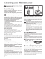
Cleaning and Maintenance
Disconnect the appliance from the electrical
supply, before carrying out any cleaning or
manteinance work.
General cleaning
Wash the enamelled components with warm soapy
water. Never use abrasive cleaners.
Frequently wash the "caps" and the "crowns" with hot
soapy water, carefully taking away any built-up of food.
The cap and crown of each burner are secured
with two screws. To separate the two pieces, lift
the cap, turn it upside down, then undo the two
fixing screws as shown in Fig. 3-b.
Regularly wipe over the hob top using a soft cloth weel
wrung out in warm water to which a little liquid detergent
has been added. Avoid the use of the following:
- household detergent and bleaches;
- impregnated pads unsuitable for non-stick saucepans;
- steel wool pads;
- bath/sink stain removers.
Should the hob top become heavily soiled, it is
recommended that a proper cleaning product is used.
This appliance cannot be cleaned with steam or with a
steam cleaning machine.
Pan supports
The pan supports are dishwasher proof.
If the marks are particularly difficult to remove, use
common non-abrasive cleaners or specific products.
Never use steel wool pads or acids.
Ignition candle
The electric ignition is obtained through a ceramic
"candle" and a metal electrode (Fig.1-lett. C). Keep
these components well clean, to avoid difficult lighting,
and check that the burner crown holes are not
obstructed.
Ceramic hob
Cleaning the hob while it is still warm.
Never use aggressive or abrasive agents, such as oven
sprays, stain or rust removers, scouring powders, or
sponges with an abrasive effect.
Special cleaning agents and ceramic hob scrapers are
available from department stores.
Slight, non-burnt soilage can be wiped off with a damp
cloth. Burnt soilage has to be removed with a scraper.
Afterwards wipe off the ceramic hob with a damp cloth.
Light metallic stains (aluminium residues) can be removed
from the cooking zone with a ceramic hob cleaning agent
such as Vitroclen when cool.
Sugar solutions, food stuffs with a high sugar content
must be removed immediately with a scraper. If this type
of soilage is not removed immediately it can cause
irreparable damage to the ceramic surface. When the
surface has cooled wipe over with a damp cloth and
Vitroclen.
Before using any detergent or cleaning agent on the
ceramic top, ensure they are recommended by the
manufacturer for use on ceramic hobs.
Do not apply any cleaning agents to hot cooking zones.
Ensure any residues are wiped off before the cooking
zones are used again.
If scratches or cracks are noticed, disconnect the
cooker from the electrical supply and call you
nearest Service Force Centre.
Keep all objects and materials which can melt
away from the cooking surface, e.g. plastics,
aluminium foil.
Care should be taken when preparing food or drinks
containing sugar. If anything of this nature
accidentally comes into contact with the ceramic
surface it must be scraped off immediately while
stlll hot and wiped away to avoid damage to the
surface.
Periodic Maintenance
Periodically ask your local Service Centre to check the
conditions of the gas supply pipe and the pressure
adjuster, if fitted.
To ensure the good operation of the hob and its safety
features, it is necessary that the taps are periodically
lubricated.
The periodic lubrication of the taps must be
carried out by
qualified personnel,
which you must refer
to also in case of
malfunctioning.
Service and original spare parts
This machine, before leaving the factory, has been
tested and studied by many experts and specialists, in
order to give you the best results.
Any repair work which needs to be carried out should
be done with the utmost care and attention.
For this reason we reccomend that for any problem you
contact the dealer who sold it to you, or our nearest
authorized Service Centre, specifying the nature of the
problem and the particular model which you own. Always
Insist on genuine original spare parts.
Fig. 3 a
b
FO 2265

7
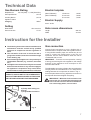
Gas Burners Rating
Rapid Burner 2,9 kW (G20) - 2,7 kW (G30/G31)
Semirapid Burner 1,9 kW
Auxiliary Burner 1,0 kW
Appliance Class 3
Category II2H3+
Setting
Natural Gas G20 - 20 mbar
Gas connection G 1/2"
The following instructions about installation and
maintenance must be carried out by qualified
personnel in compliance with the regulation in
force.
The side walls of the unit in which the hob is
going to be installed, must not exceed the height
of the working top.
Avoid installing the appliance in the proximity of
inflammable materials (e.g. curtains, tea towels
etc.).
The appliance must be electrically disconnected
before all interventions. If any electric supply to
the appliance is required to carry out the work,
ensure all the necessary precautions are followed.
THE MANUFACTURER WILL NOT ACCEPT
LIABILITY, SHOULD ANY OF THE OTHER SAFETY
INSTRUCTIONS INCORPORATED IN THIS BOOK
OR THE REGULATION IN FORCE BE IGNORED.
Technical Data
Instruction for the Installer
Electric hotplate
(Mod. EGM 636) Ø 180 mm. 1,8 kW
(Mod. EGM 626) Ø 180 mm. 1,8 kW
Ø 145 mm. 1,2 kW
Electric Supply
230 V 50 Hz
Hob recess dimensions
Length 550 mm
Width 470 mm
Gas connection
Choose fixed connections or use a flexible pipe in
stainless steel in compliance with the regulation in force.
If using flexible metallic pipes, be careful they do not
come in contact with mobile parts or they are not
squeezed. Use the same attention when the hob is
combinated with an oven.
IMPORTANT - To ensure a correct operation, a saving
of energy and the long-life of the appliance, the voltage
pressure of the appliance must correspond to the
recommended values.
The adjustable connection is fixed to the comprehensive
ramp by means of a threaded nut G 1/2". Interpose the
sealing between the components as shown in Fig. 4.
Screw the parts without forcing, adjust the connection in
the required direction and tighten everything.
IMPORTANT - When the final connection has
been made, it is essential that a thorough leak
test is carried out on the hob and installation.
Use some soapy water, never a flame.
Fig. 4
FO 0264
A) Ramp with ending nut
B) Seal
C) Adjustable connection

8
The appliance is designed to be connected to 230 V
monophase electricity supply.
The connection must be carried out in compliance with
the laws and regulations in force.
Before the appliance is connected:
1) check that the main fuse and the domestic installation
can support the load (see the rating label);
2) check that the power supply is properly earthed in
compliance with the current rules;
3) check the socket or the double pole switch used for
the electrical connection can be easily reached with
the appliance built in the forniture unit.
The appliance is supplied with a connection cable. This
has to be provided with a proper plug, able to support the
load marked on the identification plate. To connect the
plug to the cable, follow the recommendation given in Fig.
5. The plug has to be fitted in a proper socket.
If connecting the appliance directly to the electric system,
it is necessary that you install a double pole switch
between the appliance and the electricity supply, with a
minimum gap of 3 mm. between the switch contacts and
of a type suitable for the required load in compliance with
the current rules.
The connection cable has to be placed in order that, in
each part, it cannot reach a temperature higher than 90
°C.
The brown coloured phase cable (fitted in the terminal
block contact marked with "L") must always be connected
to the network phase.
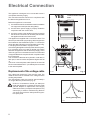
Replacement of the voltage cable
Only cable type H05V2V2-F T90 must be used. The
cable section must be suitable to the voltage and the
working temperature.
The yellow/green earth wire must be approximately 2
cm. longer than the phase wires (Fig. 6).
Under no circumstances should you attempt to
repair the appliance or replace the supply cable
yourself. Repairs or replacement of the supply
cable carried out by unexperienced persons may
cause injury or serious malfunctioning. Refer to
your local Service Centre. Always insist on genu-
ine spare parts.
Fig. 6
FO 0073
Neutral
Earth (yellow/green)
Electrical Connection
Fig. 5
FO 0238
YES
RIGID COPPER PIPE OR
FLEXIBLE PIPE IN STAINLESS
STEEL

9
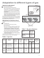
Injectors replacement
• Remove the pan supports.
• Remove the burner's caps and crowns.
• With a socket spanner 7 unscrew and remove the
injectors (Fig. 7), and replace them with the ones
required for the type of gas in use (see table 2).
• Reassemble the parts, following the same procedu-
re backwards.
• Replace the rating label (placed near the gas supply
pipe) with the relevant one for the new type of gas
supply. You can find this label in the package of the
injectors supplied with the appliance.
Should the feeding gas pressure be different or variable
compared with the required pressure, an appropriate
pressure adjuster must be fitted on the gas supply pipe,
in compliance with the rules in force.
Fig. 7
FO 0392
Adjustment of minimum level
To adjust the minimum level of the burners, proceed as
follows:
• Light the burner.
• Turn the knob on the minimum position.
• Remove the knob.
• With a thin screwdriver, adjust the by-pass screw
(see Fig. 8). If changing from natural gas to LPG,
completely tighten clockwise the screw, until a
small regular flame is obtained. If changing from
LPG to natural gas unscrew about 1/4 turn the by-
pass screw, until a small regular flame is obtained.
• Finally check the flame does not go out when
quickly turning the knob from the maximum position
to the minimum position.
This procedure can easily be carried out, anyhow the hob
has been positioned or built in the working top.
Burner Ø By-pass
in 1/100
of mm.
Auxiliary 28
Semi-rapid 32
Rapid 40
Table 1 : By-pass diameters
Table 2 : injectors
Adaptation to different types of gas
TYPE TYPE OF INJECTORS NOMINAL REDUCED NOMINAL NOMINAL
OF GAS BURNER MARKS POWER POWER POWER PRESSURE
1/100 mm INPUT k W mbar
KW m
3
/h g/h
Rapid (large) 119 2,9 0,65 0,276 -
Semi-rapid (medium) 96 1,9 0,45 0,181 - 20
Auxiliary (small) 70 1,0 0,33 0,095 -
Rapid (large) 86 2,7 0,65 - 195
Semi-rapid (medium) 71 1,9 0,45 - 137 28-30/37
Auxiliary (small) 50 1,0 0,33 - 72
NATURAL
GAS
G 20
LPG
(Buthane/
Propane)
Fig. 8
by-pass screw

10
A = Auxiliary burner
SR = Semirapid burner
R = Rapid Burner
P = Electric plate
These hobs can be inserted in a built-in kitchen unit
whose depth is between 550 and 600 mm. The hobs
dimensions are shown in the relevant diagram.
The edge of the cut out must have a minimum distance
from the rear wall of 55 mm.
If there are side walls, or sides of the furniture unit near
the hob, the cut out edges must have a minimum
distance of 100 mm.
The hobs can be installed in a kitchen unit with an
opening for insertion whose dimensions are shown in
Fig. 9.
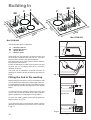
Fitting the hob to the worktop
Before fitting the hob into the cut out, an adhesive seal
must be fitted to the underside outside edge of the hob.
It is essential that no gaps are left in this seal in order to
prevent spillage near the hob seeping into the cabinet
below.
1) Remove the pan supports, the burners caps and
crowns and turn the hob upside down, taking care the
ignition candles are not damaged in this operation.
2) Place the sealing gasket all around the glass top
edge as shown in Fig. 10.
3) Fit the hob in the cut out and push it down until the
glass top and the working top come in touch, as shown
in Fig. 11.
Dimensions are given in millimeters
Building In
a) Sealing gasket
Fig. 9
Fig. 11
FO 2098
FO 2108
Fig. 10
P
P
SR
R
510
615,5
580
Mod. EGM 626
Mod. EGM 636
P
SR
R
510
615,5
580
A
A) guarnição

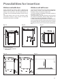
11
a) Removable panel
b) Space possibly useful for
connections
Fig. 12 Fig. 13
Fig. 15 Fig. 16
FO 1013
FO 0947
FO 0198
Kitchen unit with door
Proper arrangements must be taken in designing the
forniture unit, in order to avoid any contact with the
bottom of the hob which can be heated when it is
operated. The recommended solution is shown in Fig.
12.
The panel fitted under the hob should be easily
removable to allow an easy access if a technical
assistance intervention is needed.
Fig. 14
Kitchen unit with oven
The hob recess dimensions must comply the indication
given in Figs. 13 and 14 and must be provided with
brackets to allow a continuous supply of air.
To avoid overhating, the building in should be carried out
as shown in Figs. 15 e 16.
The hob's electric connection and the oven's one must
be carried out separately, both for safety reasons and
to allow the oven to be easily taken off the unit.
In case a hood with lenght of 600 mm. is fitted over the
hob, the hanging furniture units beside the hood must
be placed at 550 mm. minimum from the hob, to allow
the fitting and the correct use of the lid, if required (Fig.
17).
Possibilities for insertion
FO 0939
FO 0938
FO 2099
Fig. 17
595
-
 1
1
-
 2
2
-
 3
3
-
 4
4
-
 5
5
-
 6
6
-
 7
7
-
 8
8
-
 9
9
-
 10
10
-
 11
11


Electrolux EGM626K Manuale utente
- Categoria
- Piani cottura
- Tipo
- Manuale utente
- Questo manuale è adatto anche per
in altre lingue
- English: Electrolux EGM626K User manual