INTEK M-60 PLUS Manuale del proprietario
- Categoria
- Microfoni
- Tipo
- Manuale del proprietario

MULTI STANDARD PROGRAMMABLE
27 MHz CB MOBILE TRANSCEIVER
M-60 PLUS
OWNER'S MANUAL
MANUALE DI ISTRUZIONI
SAFE DRIVE RADIO !
KEEP YOUR HANDS ON THE STEERING
WHEEL WHILE DRIVING !

0678
NOTICE !
It is recommended to carefully read this owner’s manual before using the product. This will also help the user to
prevent using the radio in violation of the regulations valid in the country where the product is used, as well as to
avoid any possible interferences with other services.
CH
Declaration of Conformity
With the present declaration, we certify that the following products :
INTEK M-60 PLUS
comply with all the technical regulations applicable to the above mentioned products
in accordance with the EC Directives 2006/95/EC, 2004/108/EC, 99/5/EC.
Type of product : CB Transceiver
Details of applied standards : EN 300 433-1/-2, EN 300 135-1/-2
EN 301 489-1, EN 301 489-13
EN 60065
Manufacturer : INTEK S.R.L.
Via G. Marconi, 16
20090 Segrate, Italy
Tel. 39-02-26950451 / Fax. 39-02-26952185
E-mail : [email protected]
Notified Body : EMCCert Dr. Rasek
Boelwiese 5, 91320 Ebermannstadt
Germany
Identification Number : 0678
Contact Reference : Armando Zanni
Tel. 39-02-26950451 / Fax. 39-02-26952185
E-mail : [email protected]
Segrate, 24/02/2012 dr. Vittorio Zanetti
(General Manager)
DECLARATION OF CONFORMITY
EC Certificate of Conformity
(to EC Directive 2006/95, 2004/108, 99/5)
RoHS
2002/95/EC

Index - Introduction
- 1 -
Index - Introduction . . . . . . . . . . . . . . . . . . . . . . . . . . . . . . . . . . . . . . . . . . . . . . . . . . . . . . . . . . . . . . . . . 1
Unpacking and checking parts . . . . . . . . . . . . . . . . . . . . . . . . . . . . . . . . . . . . . . . . . . . . . . . . . . . . . . . . 2
Supplied Accessories . . . . . . . . . . . . . . . . . . . . . . . . . . . . . . . . . . . . . . . . . . . . . . . . . . . . . . . . . . . . . . . 2
Controls, Indicators and operation . . . . . . . . . . . . . . . . . . . . . . . . . . . . . . . . . . . . . . . . . . . . . . . . . . . 2-8
Installation . . . . . . . . . . . . . . . . . . . . . . . . . . . . . . . . . . . . . . . . . . . . . . . . . . . . . . . . . . . . . . . . . . . . . . . . 9
Frequency bands table - User Information . . . . . . . . . . . . . . . . . . . . . . . . . . . . . . . . . . . . . . . . . . . . . 10
Frequency band selection / programming . . . . . . . . . . . . . . . . . . . . . . . . . . . . . . . . . . . . . . . . . . . . . . 11
Table of restrictions on the use of CB transceivers . . . . . . . . . . . . . . . . . . . . . . . . . . . . . . . . . . . . . . 11
Specifications . . . . . . . . . . . . . . . . . . . . . . . . . . . . . . . . . . . . . . . . . . . . . . . . . . . . . . . . . . . . . . . . . . . . . 12
Table of restrictions on the use of CB transceivers . . . . . . . . . . . . . . . . . . . . . . . . . . . . . . . . . . . . . . . I
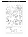
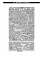
PCB - Main Board & Front Board . . . . . . . . . . . . . . . . . . . . . . . . . . . . . . . . . . . . . . . . . . . . . . . . . . . II-III
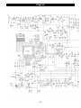
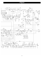
Diagram . . . . . . . . . . . . . . . . . . . . . . . . . . . . . . . . . . . . . . . . . . . . . . . . . . . . . . . . . . . . . . . . . . . . . . . . IV-V
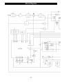
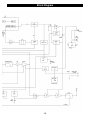
Block Diagram . . . . . . . . . . . . . . . . . . . . . . . . . . . . . . . . . . . . . . . . . . . . . . . . . . . . . . . . . . . . . . . . . .VI-VII
Notes . . . . . . . . . . . . . . . . . . . . . . . . . . . . . . . . . . . . . . . . . . . . . . . . . . . . . . . . . . . . . . . . . . . . . . . . .VIII-IX
NOTICE !
Before using this transceiver, please check that the radio has been programmed on the frequency bands,
specifications and operating modes allowed by the regulations valid in the country where the product is used. If
not, please proceed to modify the frequency band programming, as it is described in this owner’s manual. This
transceiver is factory pre-programmed on the CE European frequency band (CEPT 40CH FM 4W).
Congratulations!
Congratulations for selecting and purchasing an INTEK quality product. This transceiver includes a number of advanced
functions and systems, therefore it is definitely necessary to carefully read this owner’s manual before using the radio.
With a correct use of the product in accordance with the operating method described in this manual, the product will offer
a trouble free use for many years. INTEK is constantly engaged to develop and provide quality products meeting the
customers requirements, however any suggestion or comment on this product that might help us to improve quality are
warmly welcome. INTEK M-60 PLUS is a CB transceiver using advanced hardware and software design, it includes a
special multi-standard programmable circuit, which allows to program the specifications of the radio (frequency
bands, operating modes, transmitter power) in compliance with the regulations valid in the various European
countries. Therefore this product can be used in any country of the European Community. The radio is delivered
factory pre-programmed on the CE European frequency band (CEPT 40CH FM 4W).
English

Unpacking and Checking Parts - Supplied Accessories
- 2 -
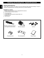
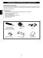
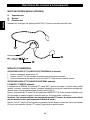
Unpacking and checking parts
Carefully unpack the product. Please identify all the parts listed below, before wasting the packaging. If any part is
missing or if the packaging shows any damage, please contact your dealer immediately.
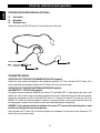
Supplied accessories
DC power cord with fuse holder and fuse, integrated with the transceiver
Standard microphone with 4-pin connector
Car mounting bracket
Car mounting bracket accessories (hardware, knobs, etc.)
Microphone bracket
Owner’s manual
Microphone bracket Car mounting bracket Owner's manual
Hardware
DC power cord with fuse holder and
fuse, integrated with the transceiver
Standard microphone
English

- 3 -
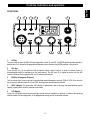
Controls, Indicators and operation
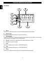
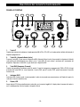
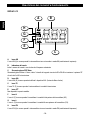
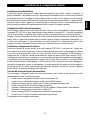
FRONT PANEL
1. A/F Key
This key allows to select the AM or FM operating mode, in both TX and RX. The AM/FM operating mode selection is
possible only if it if allowed by the programmed frequency band, otherwise the AM/FM selection is not possible.
2. ANL Key
Press the ANL key (3) to enable the ANL (Automatic Noise Limiter) function, in order to reduce electric or
electromagnetic noise or interference on the used channel. The ANL icon (D) is lighted to confirm that the ANL
function is enabled. Press again the ANL key (2) to disable the function.
3. EMG key (Emergency Channels)
This key allows quick access to one of the two pre-programmed emergency channels (CH9 or CH19). Each time this
key is pressed, radio will select CH9, then CH19, then again the normal operating channel.
4. BUSY Indicator. This green color LED indicator is lighted when radio is receiving one communication and the
squelch is open (radio is not in the automatic mute mode).
5. LCD Display
Large size LCD display with blue color backlight function for best readability in darkness. It indicates the operating
channel number, the operating mode, all the programmed settings and all the enabled functions.
1 2 3 4 5 6
7911 812 10
HL
English

- 4 -
Controls, Indicators and operation
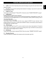
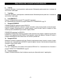
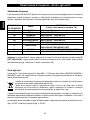
A. AM Icon
The AM icon (A) is lighted when radio has is set to the AM (Amplitude Modulation) operating mode.
B. Channel Number
It indicates the operating channel number or the frequency band ID code.
C. S/RF Digital Meter
The digital 5-bar S/RF METER (C) indicates the strength of the received signal (from S0 to S9+30) in the receive mode
and the transmitter RF output power (0 to 4W) in the transmit mode.
D. ANL Icon. The ANL Icon (D) is lighted when the ANL (Automatic Noise Limiter) is enabled.
E. ATT Icon. Not available on this model.
F. H Icon
The H Icon (F) is lighted when the transmitter is in HIGH POWER mode (4W).
G. L Icon
The L Icon (G) is lighted when the transmitter is in LOW POWER mode (1W).
H. FM Icon
The FM icon (H) is lighted when radio is set to the FM (Frequency Modulation) operating mode.
HL
A
H
G
B
CD
F
E
LCD DISPLAY
English

- 5 -
6. Up Key. Press to select the operating channel upward. By keeping a key pressed, the quick channel selection
mode will be enabled.
7. Down Key. Press to select the operating channel downward. By keeping a key pressed, the quick channel
selection mode will be enabled.
8. REMOTE PTT Jack
Connect here the optional Remote PTT Control (RPT-1). Refer to the section “TRANSMITTING MODES” at page 8.
9. AS/SQL Control
SQUELCH CONTROL (SQUELCH manual adjustment)
The SQUELCH control allows to silent the receiver by cutting the background noise, when no signals are received. Turn
the knob clockwise until the background noise is cut. Turn the knob counter clockwise (SQUELCH opening) in order to
listen to the weakest signals.
AS CONTROL (SQUELCH fixed setting)
The AS function allows to automatically silent the receiver, avoding the SQUELCH manual adjustment. A fixed
SQUELCH threshold is factory pre-set. To enable the fixed SQUELCH function, turn the knob fully counter clockwise to
the AS position, until a click noise is heard.
10. OFF/VOL Control
Use this knob to switch radio ON and OFF, as well as to adjust the receiver volume to the desired level. To adjust the
receiver volume in case no signals are received on the operating channel, open the SQUELCH and then adjust the
receiver volume using the background noise as a reference.
11. EXT MIC Jack
Connect here the optional external microphone ESM-444. Refer to the sections “TRANSMITTING MODES” at page 8.
12. Microphone Connector
Connect the standard 4-pin microphone to this connector and turn the connector ring to lock it.
Controls, Indicators and operation
English

IMPORTANT !
Do never attempt to open the cabinet of the transceiver. No user serviceable parts inside. Internal modifications or
tampering may cause damage to the product, modify its technical specifications and will void warranty rights. If
service or repair are required, please go to an authorised service centre or specialized technician.
Controls, Indicators and operation
- 6 -
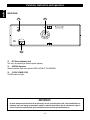
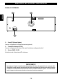
REAR PANEL
13. EXT (External Speaker) Jack
This jack is for connecting an external speaker (optional).
14. ANTENNA Connector
Antenna connector. Refer to the sections INSTALLATION OF THE ANTENNA.
15. 13.2VDC POWER CORD
13.2VDC power cord input.
English
ANT
EXT
DC
13.2V
1413
15

- 7 -
Controls, Indicators and operation
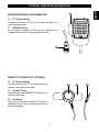
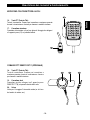
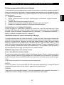
MICROPHONE WITH 4-PIN CONNECTOR
English
16. PTT (Push-to-Talk) Key
Transmitter key. Press the PTT key (16) to transmit and release it to
return to the receive mode.
17. MICROPHONE Plug
4-pin microphone connector with locking ring. Connect it to the
microphone connector (12) on the front panel of the radio.
16
17
REMOTE PTT CONTROL RPT-1 (OPTIONAL)
18. PTT (Push-to-Talk) Key
Transmitter key. Press the PTT key (18) to transmit and
release it to return to the receive mode.
19. Remote PTT Jack
Connect this jack to the REMOTE PTT socket (8) on the
front panel of the radio.
20. Velcro Strap
Velcro strap for installing the remote PTT control in a
convenient location, such as on the speed shift lever or
on the steering wheel.
18 20 19

- 8 -
TRANSMITTING MODES
OPERATION IN PTT MODE WITH STANDARD MICROPHONE (supplied)
Connect the 4-pin standard microphone to the microphone connector (12). Press and hold the PTT button (16) to
transmit and speak into microphone. Release the PTT button (16) to return to receive mode.
OPERATION IN PTT MODE WITH EXTERNAL MICROPHONE (optional)
AND REMOTE PTT CONTROL BOX (optional)
The optional external microphone (ESM-444) and remote PTT control Box (RPT-1) allow operating the radio in total
comfort and safety, without using the standard microphone that may be disconnected from the radio and removed.
Connect the microphone jack (23) into the EXT MIC socket (11). Connect the remote PTT control jack (19) to the
REMOTE PTT socket (8). Install the remote PTT control in a convenient location, such as on the speed shift lever or on
the steering wheel, using the velcro strap (20), for your most comfortable operation during driving.
WARNING ! Pay the greatest attention to installation of the remote PTT control and its connecting cable, in order
for these not to interfere with your driving operation.
Press and hold the PTT button (18) to transmit and speak into microphone (22) with normal voice. Release the PTT
button (18) to return to receive mode.
Controls, Indicators and operation
English
EXTERNAL MICROPHONE ESM-444 (OPTIONAL)
21. Neck Bracket
22. Microphone
23. Microphone Jack
Connect this jack to the EXT MIC socket (11) on the front panel of the radio.
23
22
21

- 9 -
Installation
Installation
Before installing the main unit in the vehicle, check and select the most convenient location, in order that the radio will be
easy to reach and comfortable to operate, without disturbing or interfering with the vehicle drive. Use the supplied
bracket and hardware to install the radio. The bracket screws must be well tightened in order not to become loosen with
the vehicle vibrations. The car mounting bracket can be installed over or below the radio and the radio may be inclined
as desired according to the specific type of installation (under dashboard or track cabin roof installation).
Installation of the Main Unit
Before connecting the radio to the vehicle electric system, make sure that radio is switched off, with the OFF/VOL knob
(10) completely turned counter clockwise at OFF position. The DC power cable (15) of the radio is complete with a fuse
holder with fuse located on the red positive (+) wire. Connect the DC power cable to the vehicle electric system, with
special attention to respect correct polarity, even if the radio is protected against polarity inversion. Connect the red wire to
the positive (+) pole and the black wire to the negative (-) pole of the vehicle electric system. Make sure that the wires and
terminals are firmly and stably connected, in order to prevent cables from disconnecting or causing short circuits.
Installation of the Antenna
A specific mobile antenna adjusted for 27 MHz frequency range must be used. The antenna installation must be done by
a specialised technician or service centre. Please pay special attention to carefully install the antenna on the vehicle with
perfect connection to ground. Before connecting the antenna to the radio, it is necessary to check the correct operation
of the antenna with low standing wave ratio (S.W.R.), using adequate instruments. If not, the transmitter circuit of the
radio could be damaged. The antenna must be usually installed on the highest part of the vehicle, free from obstacles
and as far away as possible from any source of electric or electromagnetic noise. The RF antenna coaxial cable must
not be damaged or pressed on its way between antenna and the radio. The correct operation of the antenna and the low
standing wave ratio (S.W.R.) must be checked periodically. Connect the RF antenna coaxial cable to the antenna
connector (14), located on the rear side of the radio.
Checking Operation of the Radio
Once radio has been connected to the vehicle electric system and to the antenna, the correct operation of the system
may be checked. Please proceed as follows :
1) Check that the power cable (15) is correctly connected.
2) Check that the RF antenna coaxial cable is correctly connected.
3) Connect the standard 4-pin microphone to the connector (12), located on the front side of the radio.
4) Rotate the AS/SQL knob (9) counter clockwise.
5) Turn radio on using the OFF/VOL knob (10) and adjust volume to the desired level.
6) Select the desired channel, using the Up/Down Keys (6, 7).
7) Rotate the AS/SQL knob (9) clockwise, to cut the background noise.
8) Press the PTT key (16) to transmit and release it to receive.
English

Frequency bands table - User Information
- 10 -
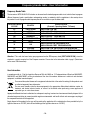
Frequency Bands Table
The transceiver INTEK M-60 PLUS includes an advanced multi-standard programmable circuit, which allows to program
different frequency bands, specifications and operating modes, in conformity with the regulations in the country where
the product is used. 9 programmable frequency bands are available, as per the below table :
Attention ! This radio has been factory pre-programmed on the CE frequency band (CEPT 40CH FM 4W), since this
standard is currently accepted in all the European countries. Please refer to the information table at page I (Restrictions
on the use of CB transceivers).
User Information
in accordance with art. 13 of the Legislative Decree of 25th July 2005, no. 15 ”Implementation of Directives 2002/95/EC,
2002/96/EC and 2003/108/EC, relative to reduction of the use of hazardous substances in electrical and electronic
equipment, in addition to waste disposal”.
The crossed bin symbol shown on the equipment indicates that at the end of its working life the product must
be collected separately from other waste.
The user must therefore take the above equipment to the appropriate differentiated collection centres for
electronic and electro technical waste, or return it to the dealer when purchasing a new appliance of
equivalent type, in a ratio of one to one.
Appropriate differentiated waste collection for subsequent recycling, treatment and environment-friendly disposal of the
discarded equipment helps to prevent possible negative environmental and health effects and encourages recycling of
the component materials of the equipment.
Illegal disposal of the product by the user will be punished by application of the administrative fines provided for by the
legislative decree no. 22/1997 (article 50 and following of the legislative decree no. 22/1997).
PD
FREQUENCY BAND
ID CODE
COUNTRY
SPECIFICATIONS
(Channels, Operating Modes, TX Power)
E1 ITALY/SPAIN
40CH AM / FM 4W
I2 ITALY
36CH AM / FM 4W
dE GERMANY
80CH FM 4W - 12CH AM 1W
d2 GERMANY
40CH FM 4W - 12CH AM 1W
EU EUROPE/FRANCE
40CH FM 4W - 40CH AM 1W
CE CEPT
40CH FM 4W
UUK
40CH FM 4W UK FREQUENCIES
40CH FM 4W CEPT FREQUENCIES
PL POLAND
POLAND
40CH AM / FM 4W POLISH FREQUENCIES
40CH AM 1W / FM 4W POLISH FREQUENCIES
English

Frequency band selection / programming
- 11 -
Frequency Band Selection / Programming
This two-way CB radio has to be programmed and exclusively used on a frequency band allowed in the country where
the product is used. When radio is switched ON, the current programmed frequency band code will be displayed
(blinking) for about 3 seconds. To program a different frequency band, proceed as follows :
1) Turn OFF the radio.
2) Press and keep pressed the UP key (6), then turn ON the radio using the OFF/VOL knob (10).
3) The current frequency band code (B) will blink on the LCD display (5).
4) Now select the new desired frequency band code by pressing the Up (6) or Down keys (7).
5) Wait for about 5 seconds to confirm and store the new selected frequency band code.
UK/CE CHANNELS SELECTION (FREQUENCY BAND "U")
The "U" band (UK/CE band) includes both UK and CE channels, this band is for use in the UK. All channels can be
scrolled using the Up (6) or Down (7) keys. If a UK channel is selected, the display (5) will show the channel number
(B) and the indication "U". If a CEPT channel is selected the display (5) will show the channel number (B) and the
indication "C".
Table of Restrictions on the Use of CB Transceivers (page I)
The following information are to be considered only just as an indication. They are believed to be correct at the time of
printing this operating manual. It is however the user’s responsibility to check that, in the country where radio is used, the
regulations for the use of CB transceivers have not been modified. User is therefore suggested to contact the local
dealer or local authority, in order to check the current regulations for the use of CB transceivers, before operating this
product. The manufacturer does not take any responsibility if the product is used in violation of the regulations of the
country where the product is used.
Addendum (Updated information on national restrictions)
BELGIUM, UK, SPAIN, SWITZERLAND
In order to use this transceiver in Belgium, UK, Spain and Switzerland, residence must have an individual licence. Users
coming from abroad may freely use the radio in FM mode, while in order to use it in AM mode they must hold a licence
released in their own country.
ITALY
Foreigners arriving in Italy must get an Italian authorization.
AUSTRIA
Austria does not allow using multi standard programmable CB radios. It is recommended
to carefully follow this directives and not to use the product in the Austrian territory.
GERMANY
Along some border areas in Germany, the radio can not be used as a base station from
channel 41 to channel 80. Refer to local authority (notification office) for details.
English

Specifications - Optional Accessories
- 12 -
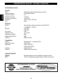
Specifications
General
Channels 40 FM (refer to the frequency bands table at page 10)
Frequency range 27 MHz Citizen Band
Frequency control P.L.L.
Operatine temperature -10°/+55°C
DC input voltage 13.2Vdc ±15%
Size 115 (L) x 43 (H) x 165 (D) mm
Weight 600 gr.
Receiver
System Double conversion, CPU controlled super-heterodine
IF 1° 10.695 MHz / 2° 455 KHz
Sensitivity 0.5uV (FM)
0.5uV (AM)
Audio output 2.5W
Audio distorsion <8% at 1 KHz
Image rejection 65dB
Signal/noise ratio 45dB
Current drain 300mA (stand-by)
Transmitter
System CPU controlled P.L.L. systhesizer
Maximum RF power 4W at 13.2Vdc
Modulation 85% to 90% (AM)
1.8 KHz ±0.2 KHz (FM)
Impedance 50 ohm unbalanced
Current drain 1200mA (at no modulation)
Opzional Accessories
ESM-444 External microphone with adjustable flexible boom and neck support
RPT-1 Remote PTT Control Box with velcro strap and 2 mt cable with jack
RECOMMENDED BY INTEK !
LEADER IN CB 27 MHz
CAR & TRUCK MOBILE ANTENNAS
English

Indice - Introduzione
- 13 -
Indice - Introduzione . . . . . . . . . . . . . . . . . . . . . . . . . . . . . . . . . . . . . . . . . . . . . . . . . . . . . . . . . . . . . . . 13
Disimballaggio e verifica delle parti . . . . . . . . . . . . . . . . . . . . . . . . . . . . . . . . . . . . . . . . . . . . . . . . . . . 14
Accessori forniti . . . . . . . . . . . . . . . . . . . . . . . . . . . . . . . . . . . . . . . . . . . . . . . . . . . . . . . . . . . . . . . . . . . 14
Descrizione dei comandi e funzionamento . . . . . . . . . . . . . . . . . . . . . . . . . . . . . . . . . . . . . . . . . . 15-20
Installazione e collegamenti elettrici . . . . . . . . . . . . . . . . . . . . . . . . . . . . . . . . . . . . . . . . . . . . . . . . . . 21
Tabella bande di frequenza - Avviso agli utenti . . . . . . . . . . . . . . . . . . . . . . . . . . . . . . . . . . . . . . . . . 22
Selezione / programmazione della banda di frequenza . . . . . . . . . . . . . . . . . . . . . . . . . . . . . . . . . . . 23
Tabella delle restrizioni all' uso dei ricetrasmettitori CB . . . . . . . . . . . . . . . . . . . . . . . . . . . . . . . . . . 23
Caratteristiche tecniche . . . . . . . . . . . . . . . . . . . . . . . . . . . . . . . . . . . . . . . . . . . . . . . . . . . . . . . . . . . . 24
Tabella delle restrizioni all' uso dei ricetrasmettitori CB . . . . . . . . . . . . . . . . . . . . . . . . . . . . . . . . . . . I
Circuito stampato Main Board e Front Board . . . . . . . . . . . . . . . . . . . . . . . . . . . . . . . . . . . . . . . . . II-III
Schema elettrico . . . . . . . . . . . . . . . . . . . . . . . . . . . . . . . . . . . . . . . . . . . . . . . . . . . . . . . . . . . . . . . . . IV-V
Schema a blocchi . . . . . . . . . . . . . . . . . . . . . . . . . . . . . . . . . . . . . . . . . . . . . . . . . . . . . . . . . . . . . . .VI-VII
Note . . . . . . . . . . . . . . . . . . . . . . . . . . . . . . . . . . . . . . . . . . . . . . . . . . . . . . . . . . . . . . . . . . . . . . . . . .VIII-IX
IMPORTANTE !
Prima di utilizzare la ricetrasmittente, verificare che la stessa sia programmata per operare sulle
bande di frequenza e nei modi previsti dalle norme di legge in vigore nel paese in cui la radio viene
utilizzata. Diversamente procedere alla modifica della programmazione, come indicato in questo
manuale di istruzioni. La radio è pre-programmata all' origine sulla banda di frequenza europea CE
(CEPT 40CH FM 4W).
Congratulazioni !
Congratulazioni per aver scelto ed acquistato un prodotto di qualità INTEK. Questo ricetrasmettitore dispone di numerose
funzioni avanzate e vari dispositivi, pertanto è assolutamente necessario leggere attentamente questo manuale di
istruzioni prima di utilizzare l' apparecchio. Con un uso corretto secondo quanto è indicato nel manuale di istruzioni, l'
apparecchio garantirà un servizio senza problemi per molti anni. Ci impegnamo costantemente a fornire prodotti di
qualità che rispondano alle vostre esigenze, ma siamo comunque sempre molto interessati a ricevere eventuali vostri
commenti o suggerimenti su questo prodotto, che ci aiutino nel continuo miglioramento della qualità. INTEK M-60
PLUS è un ricetrasmettitore con caratteristiche tecniche di hardware e software molto avanzate e dispone di un circuito
di tipo Multi Standard programmabile che consente di configurare i vari parametri dell' apparecchio (bande di
frequenza, modi operativi, potenza del trasmettitore) in modo conforme alle norme di legge in vigore nei vari paesi
della Comunità Europea. Pertanto questa ricetrasmittente può essere utilizzata in un qualsiasi paese della Comunità
Europea. L' apparecchio viene consegnato pre-programmato sulla banda CE (CEPT 40CH FM 4W).
Italiano

Disimballaggio e verifica delle parti - Accessori forniti
Disimballaggio e verifica delle parti
Disimballate accuratamente il ricetrasmettitore. Si raccomanda di identificare tutte le parti elencate nella tabella
seguente, prima di eliminare l’imballo. Se vi sono stati danni o mancanze durante la spedizione, contattate
immediatamente il vostro fornitore.
Accessori forniti
Cavetto di alimentazione DC con porta fusibile e fusibile integrato con il ricetrasmettitore
Microfono standard con connettore a 4 poli
Staffa di montaggio per veicolo
Accessori per montaggio staffa (viti, pomelli, ecc.)
Staffa di supporto per microfono
Manuale di istruzioni
Supporto per il microfono Staffa di montaggio Manuale di istruzioni
Viteria
Cavo di alimentazione
con porta fusibile e fusibile
integrato con il ricetrasmettitore
Microfono
- 14 -
Italiano

Descrizione dei comandi e funzionamento
- 15 -
1. Tasto A/F
Questo tasto consente di selezionare il modo operativo AM o FM, in TX e RX, se il modo scelto è abilitato dalla banda di
frequenza programmata.
2. Tasto ANL (Automatic Noise Limiter)
Premere il tasto ANL (2) per inserire il dispositivo ANL (Automatic Noise Limiter) che permette la riduzione dei disturbi
radio elettrici ed elettromagnetici sul canale in uso. L' icona ANL (D) sarà accesa a conferma dell' inserimento del
dispositivo. Ripremere il tasto ANL (2) per disattivare il dispositivo ANL.
3. Tasto EMG (Emergency Channels)
Questo tasto permette la selezione rapida di uno dei 2 canali di emergenza pre-programmati (CH9 o CH19). Ad ogni
pressione del tasto EMG (3), viene impostato il canale CH9, quindi il canale CH19, quindi nuovamente il normale
canale in uso.
4. Indicatore BUSY
Indicatore LED di colore verde, è acceso quando la radio sta ricevendo una comunicazione e lo Squelch è aperto (la
radio non si trova in modalità mute).
5. Display LCD
Ampio display LCD di tipo retroilluminato in colore blu, per la massima leggibilità. Il display indica il numero del canale in
uso, il modo operativo e tutte le funzioni e i dispositivi attivati.
1 2 3 4 5 6
7911 812 10
PANNELLO FRONTALE
Italiano

Descrizione dei comandi e funzionamento
- 16 -
A. Icona AM
L' icona AM (A) è accesa quando il ricetrasmettitore riceve e trasmette in modo AM (modulazione di ampiezza).
B. Indicazione del canale
Indica il numero del canale in uso o la banda di frequenza selezionata.
C. Strumento a barre S/RF Meter
Strumento digitale S/Meter a 5 barre, indica l' intensità del segnale ricevuto da S0 a S9+30 in ricezione e la potenza RF
di uscita da 0 a 4W in trasmissione.
D. Icona ANL
L' icona ANL (D) è accesa quando è abilitato il dispositivo ANL (Automatic Noise Limiter).
C. Icona TX
L’ icona TX (C) è accesa quando il ricetrasmettitore è in modalità trasmissione.
E. Icona ATT
Non disponibile in questo modello.
F. Icona H
L' icona H (F) è accesa quando il trasmettitore è in modalità alta potenza del trasmettitore (4W).
G. Icona L
L' icona L (G) è accesa quando il trasmettitore è in modalità bassa potenza del trasmettitore (1W).
H. Icona FM
L' icona FM (H) è accesa quando il ricetrasmettitore riceve e trasmette in modo FM (modulazione di frequenza).
DISPLAY LCD
HL
A
H
G
B
CD
F
E
Italiano

- 17 -
Descrizione dei comandi e funzionamento
6. Tasto Up
Premere per selezionare il canale operativo in modo crescente. Mantenendo premuto questo tasto, la selezione dei
canali avverrà in modo rapido.
7. Tasto Down
Premere per selezionare il canale operativo in modo decrescente. Mantenendo premuto questo tasto, la selezione dei
canali avverrà in modo rapido.
8. Presa REMOTE PTT
Presa per il collegamento del comando PTT remoto RPT-1 (opzionale).
Per il funzionamento fare riferimento al paragrafo "MODALITA' DI TRASMISSIONE" a pag. 20.
9. Manopola AS/SQUELCH
COMANDO SQUELCH (regolazione manuale SQUELCH)
Il comando SQUELCH permette di silenziare il ricevitore, eliminando il rumore (fruscio) di fondo in assenza di segnali.
Ruotare la manopola in senso orario sino a quando scompare il rumore di fondo. Ruotare la manopola in senso
antiorario (apertura dello SQUELCH) per ascoltare i segnali più deboli.
COMANDO AS (regolazione fissa SQUELCH)
E' disponibile la funzione AS per silenziare il ricevitore in modo automatico, senza eseguire la regolazione manuale dello
SQUELCH. Una regolazione fissa dello SQUELCH è pre-impostata in origine. Per impostare la funzione AS, ruotare la
manopola completamente in senso antiorario fino a farla scattare in posizione AS.
10. Manopola OFF/VOL
Manopola di accensione e spegnimento della radio. Permette la regolazione del volume di ascolto. In assenza di segnali
sul canale in uso, si consiglia di aprire lo SQUELCH e quindi di regolare il volume al livello desiderato utilizzando come
riferimento il rumore (fruscio) di fondo.
11. Presa EXT MIC
Presa per il collegamento del microfono esterno opzionale ESM-444. Per il funzionamento fare riferimento al
paragrafo "MODALITA' DI TRASMISSIONE" a pag. 20.
12. Presa per microfono
Collegare il microfono tradizionale a 4-poli in dotazione a questa presa, bloccandolo tramite l’ apposita ghiera.
Italiano

IMPORTANTE !
Non tentare mai di aprire il contenitore del ricetrasmettitore. All' interno dell' apparecchio non vi sono parti utili o
utilizzabili dall' utente. Interventi o manomissioni del circuito interno della radio possono causare danni alla stessa
o modificarne le caratteristiche tecniche ed inoltre violano e invalidano il diritto alla garanzia. In caso di interventi
tecnici, rivolgersi esclusivamente ad tecnico o ad un centro di assistenza autorizzato.
13. Presa EXT (External Speaker)
Presa per il collegamento di un altoparlante esterno (opzionale).
14. Connettore di antenna (SO-239)
Presa per il collegamento dell' antenna. Vedi capitoli "installazione e collegamenti elettrici".
15. Entrata POWER 13.2VDC
Entrata del cavetto di alimentazione DC in dotazione.
PANNELLO POSTERIORE
ANT
EXT
DC
13.2V
1413
15
Descrizione dei comandi e funzionamento
- 18 -
Italiano
La pagina si sta caricando...
La pagina si sta caricando...
La pagina si sta caricando...
La pagina si sta caricando...
La pagina si sta caricando...
La pagina si sta caricando...
La pagina si sta caricando...
La pagina si sta caricando...
La pagina si sta caricando...
La pagina si sta caricando...
La pagina si sta caricando...
La pagina si sta caricando...
La pagina si sta caricando...
La pagina si sta caricando...
La pagina si sta caricando...
La pagina si sta caricando...
-
 1
1
-
 2
2
-
 3
3
-
 4
4
-
 5
5
-
 6
6
-
 7
7
-
 8
8
-
 9
9
-
 10
10
-
 11
11
-
 12
12
-
 13
13
-
 14
14
-
 15
15
-
 16
16
-
 17
17
-
 18
18
-
 19
19
-
 20
20
-
 21
21
-
 22
22
-
 23
23
-
 24
24
-
 25
25
-
 26
26
-
 27
27
-
 28
28
-
 29
29
-
 30
30
-
 31
31
-
 32
32
-
 33
33
-
 34
34
-
 35
35
-
 36
36


INTEK M-60 PLUS Manuale del proprietario
- Categoria
- Microfoni
- Tipo
- Manuale del proprietario
in altre lingue
- English: INTEK M-60 PLUS Owner's manual
Documenti correlati
-
INTEK M-899 VOX Manuale del proprietario
-
-
-
INTEK M-100 Plus Manuale del proprietario
-
-
-
-
-
-