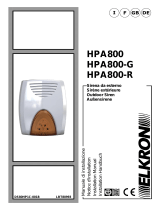
CAME PXSEA-PXSEG SIREN Guida d'installazione
- Tipo
- Guida d'installazione

PXSEA - PXSEG
www.came.com
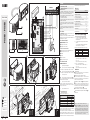
280
140
135
CENTRAL
A
B
C
G
F
D
E
I
J
H
🅰
🅳 🅴
🅱 🅲
Italiano
IT
English
EN
Français
FR
Русский
RU
FA00532M4A
FA00532M4A - ver. 1 - 02/2018
ITALIANO
Avvertenze generali
• Importanti istruzioni per la sicurezza delle persone: LEG-
GERE ATTENTAMENTE!
• L’installazione, la programmazione, la messa in servizio e la
manutenzione devono essere eettuate da personale qualificato
ed esperto e nel pieno rispetto delle normative vigenti.
• Indossare indumenti e calzature antistatiche nel caso di inter-
vento sulla scheda elettronica.
• Conservare queste avvertenze.
• Togliere sempre l’alimentazione elettrica durante le operazioni
di pulizia o di manutenzione.
• Il prodotto deve essere destinato solo all’uso per il quale è
stato espressamente studiato. Ogni altro uso è da considerarsi
pericoloso.
• Il costruttore non può comunque essere considerato respon-
sabile per eventuali danni derivanti da usi impropri, erronei ed
irragionevoli.
Descrizione
Sirena da esterno auto-alimentata con contenitore in ABS e lam-
peggiatore a LED in policarbonato.
L'apparecchio è protetto da tamper per la rilevazione dei tentativi
di apertura del coperchio, la rimozione della sirena dalla parete e
la neutralizzazione con schiuma.
Descrizione delle parti
A Tamper anti-strappo.
B Lampeggiatore frontale (LED1).
C Lampeggiatore inferiore (LED2).
Descrizione della scheda interna
D Fusibile di protezione inversione polarità batteria (F 3,15A).
E Fusibile di protezione scheda (F 3,15A).
F Morsettiera.
G Dip-switch.
H Tamper anti-apertura.
I Tamper anti-strappo ed apertura.
Descrizione morsetti
TAMPER Contatto tamper.
– Negativo ingressi lampeggiatori.
LED1 Ingresso per il comando del lampeggiatore frontale B.
Con un negativo (–) collegato all'ingresso i LED1 si accendono.
LED2 Ingresso per il comando del lampeggiatore inferiore C.
Con un negativo (–) collegato all'ingresso, i LED2 si accendono.
+ Positivo ingresso LOCK
LOCK Ingresso per il blocco della sirena (vedi esempio J).
Dopo 30 secondi dalla disattivazione del blocco il funzionamento
normale della sirena viene ripristinato.
C Ingresso per il comando della sirena.
Un positivo (+) collegato a questo ingresso blocca la sirena.
La mancanza del positivo a tale morsetto, oppure un negativo (-)
collegato al C, attiva la sirena.
– + Ingresso alimentazione 12 VDC.
Tipo e sezione cavi
Tipo di cavo da usare FROR CEI 20-22
Collegamento Lunghezza cavo
1 < 35 m 35 < 70 m
Alimentazione dalla centrale 2 x 0,5 mm22 x 0,75 mm2
Circuito tamper 2 x 0,22 mm22 x 0,5 mm2
Ingresso comando sirena 1 x 0,22 mm21 x 0,5 mm2
Ingressi LED sirena 2 x 0,22 mm22 x 0,5 mm2
Blocco sirena con chiave esterna 2 x 0,22 mm22 x 0,5 mm2
N.B. Qualora i cavi abbiano lunghezza diversa rispetto a quan-
to previsto in tabella, si determini la sezione dei cavi sulla base
dell’eettivo assorbimento dei dispositivi collegati.
Per i collegamenti che prevedano più carichi sulla stessa linea
(sequenziali), il dimensionamento a tabella deve essere riconsi-
derato sulla base degli assorbimenti e delle distanze eettivi. Per
i collegamenti di prodotti non contemplati in questo manuale fa
fede la documentazione allegata ai prodotti stessi.
Dati tecnici
Tipo PXSEA-PXSEG
Alimentazione DC (V) 12÷15
Assorbimento massimo (A) 1,5
Assorbimento in stand-by (mA) 30
Tipo cono magnetodinamico (Ω) 8
Livello di pressione sonora ad 1 metro db(A) 108
Peso, batteria esclusa (Kg) 2,5
Temperatura di esercizio (°C) -25 ÷ 55
Umidità relativa senza condensa (%) 25 ÷ 75
Grado di protezione (IP) 44
Classe ambientale III
Conformità normativa EN 50131-4
Grado 2
Selezioni funzioni (Dip-switch) G
(1) ON Blocco sirena attivo (condizione di default).
OFF Dopo 30 secondi, la sirena è pronta per essere
attivata dalla centrale.
(2) ON Il lampeggiatore lampeggia per il tempo di allarme
impostato.
OFF Il lampeggiatore lampeggia fino al ripristino del
comando sul morsetto “C” (contatto N.C.).
(3-4) Regolano il tempo di allarme della sirena come segue:
Dip-switch 3 Dip-switch 4 Tempo di allarme (secondi)
OFF OFF 600
ON OFF 420
OFF ON 180 (default)
ON ON 120
(5-6) 5 OFF - 6 ON (condizione di default)
L'ingresso LED 1 funziona con comando negativo (–).
5 ON - 6 OFF
L'ingresso LED1 funziona con comando positivo (+)
(7-8) 7 OFF - 8 ON (condizione di default)
L'ingresso LED 2 funziona con comando negativo (–)
7 ON - 8 OFF
L'ingresso LED2 funziona con comando positivo (+)
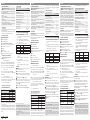
Installazione
🅰 Rimuovere il guscio della sirena. Il guscio viene mantenuto
attaccato alla base da apposite bretelle.
🅱 Rimuovere la protezione metallica anti-schiuma.
🅲 Con l'aiuto di un trapano aprire uno o più fori necessari al
passaggio dei cavi di collegamento, completare l'operazione ap-
ponendo sui fori i passacavi in dotazione.
Verificare che lo switch 1 SW1 G si trovi in posizione ON.
🅳 Dopo avere tracciato, con l'aiuto della dima in dotazione, la
posizione corretta dei fori di fissaggio dei tasselli, fissare la base
della sirena al muro, avendo cura di verificare la planarità dell'a-
rea in cui poggia il tamper anti-strappo A.
🅴 Inserire la batteria (non inclusa) ed eseguire il cablaggio.
Prima di richiudere la sirena portare lo switch 1 SW1 G in
posizione OFF.
Il prodotto è conforme alle direttive di riferimento vigenti.
Dismissione e smaltimento. Non disperdere nell’ambiente
l’imballaggio e il dispositivo alla fine del ciclo di vita, ma smal-
tirli seguendo le norme vigenti nel paese di utilizzo del prodotto.
I componenti riciclabili riportano simbolo e sigla del materiale.
I DATI E LE INFORMAZIONI INDICATE IN QUESTO MANUALE SONO DA RITENERSI SU-
SCETTIBILI DI MODIFICA IN QUALSIASI MOMENTO E SENZA OBBLIGO DI PREAVVISO.
LE MISURE, SE NON DIVERSAMENTE INDICATO, SONO IN MILLIMETRI.

FA00532M4A - ver. 1 - 02/2018
ENGLISH
General Precautions
• Important people-safety instructions: READ CAREFULLY!
• Installing, programming, commissioning and maintenance
must only be done by qualified, expert sta and in full compli-
ance with the applicable law.
• Wear antistatic protective clothing when working on the con-
trol board.
• Keep these precautions.
• Always cut o the mains power when doing cleaning and
maintenance jobs.
• This product must only be used for its specifically intended
purpose. Any other use is dangerous.
• The manufacturer declines all liability for any damage as a
result of improper, incorrect or unreasonable use.
Description
Self-powered outdoor siren with ABS casing and LED polycar-
bonate LED flashing light.
This device is protected from tampering attempts at opening the
cover, removing the siren from the wall and foaming.
Description of parts
A Anti-tear tamper-proof switch.
B Front flashing light (LED 1).
C Lower flashing light (LED 2).
Description of the internal control-board
D F 3.15A fuse to protect battery from inverting its polarity.
E Control-board F 3.15A protective fuse.
F Terminals.
G Dip-switch.
H Anti-opening tamper-proof switch.
I Anti-opening and anti-tearing tamper-proof switch.
Description of the terminals
TAMPER Tamper contact.
– Negative flashing-light inputs.
LED 1 Input for controlling the front flashing-light B.
With a negative (-) connected to the input, the LEDs 1 turn on.
LED 2 Input for controlling the lower flashing-light C.
With a negative (-) connected to the input, the LEDs2 turn on.
+ Positive LOCK input
LOCK Input for locking the siren (see example J).
After 30 seconds from deactivation, the siren begins working
normally again.
C Input for controlling the siren.
A positive (+) connected to this input, blocks the siren.
When no positive Volts are connected to this terminal, or negative
Volts are connected to C, the siren is activated.
– + 12 V DC power-supply input.
Type and section of cables
Type of cable to use FROR CEI 20-22
Connection Cable length
1 < 35 m 35 < 70 m
Power-supply to control unit 2 x 0.5 mm22 x 0.75 mm2
Tamper circuit 2 x 0.22 mm22 x 0.5 mm2
Siren control input 1 x 0.22 mm21 x 0.5 mm2
Siren-LED inputs 2 x 0.22 mm22 x 0.5 mm2
Siren locking with external key 2 x 0.22 mm22 x 0.5 mm2
N.B. If cable lengths dier from those specified in the table, es-
tablish the cable sections depending on the actual power draw of
the connected devices.
For multiple, sequential loads along the same line, the dimensions
on the table need to be recalculated according to the actual power
draw and distances. For connecting products that are not con-
templated in this manual, see the literature accompanying said
products.
Technical data
Type PXSEA-PXSEG
Power supply DC (V) 12÷15
Maximum draw (A) 1.5
Consumption in stand-by mode (mA) 30
Type of magneto-dynamic code (Ω) 8
Sound pressure level at 1 meter db(A) 108
Weight, excluding battery (kg) 2.5
Operating temperature (°C) -25 ÷ 55
Relative humidity without condensation (%) 25 ÷ 75
Protection rating (IP) 44
Environmental class III
Regulatory compliance EN 50131-4
Grade 2
Functions selection (Dip-switch) G
(1) ON Siren lock active by default.
OFF After 30 seconds, the siren is ready to be activated
by the control unit.
(2) ON The light flashes for the preset alarm time.
OFF The light flashes until the command on terminal “C”
(N.C. contact) is restored.
(3-4) These set the siren's alarm times, as follows:
Dip-switch 3 Dip-switch 4 Alarm time (seconds)
OFF OFF 600
ON OFF 420
OFF ON 180 (default)
ON ON 120
(5-6) 5 OFF - 6 ON by default
The LED 1 input works with a negative (–) command.
5 ON - 6 OFF
The LED 1 input works with a positive (+) command.
(7-8) 7 OFF - 8 ON by default
The LED 2 input works with a negative (–)command.
7 ON - 8 OFF
The LED 2 input works with a positive (+) command.
Installing
🅰Remove the shell from around the siren. The shell is kept
hooked to the base by a pair of rods.
🅱 Remove the anti-foaming metal protection.
🅲 Drill one or more holes, to pass the connection cables through.
Complete the procedure by fitting the supplied cable glands to
the holes.
Make sure that switch 1 SW1 G is set to ON.
🅳 Use the stencil to trace the proper placement of the holes
for fitting the dowels, fit the base of the siren against the wall,
making sure that the anti-tear tamper-proof device is resting on
a flat surface. A.
🅴 Fit the battery (not included) and finish the wiring.
Before removing the siren, set switch 1 SW1 G to OFF.
This product complies with the law.
Decommissioning and disposal. Dispose of the packaging
and the device at the end of its life cycle responsibly, in com-
pliance with the laws in force in the country where the product
is used. The recyclable components are marked with a symbol
and the material's ID marker.
THE DATA PRESENTED IN THIS MANUAL MAY BE SUBJECT TO CHANGE, AT ANY
TIME, AND WITHOUT NOTICE. MEASUREMENTS, UNLESS OTHERWISE STATED, ARE
IN MILLIMETERS.
FRANÇAIS
Instructions générales
• Instructions importantes pour la sécurité des personnes :
À LIRE ATTENTIVEMENT !
• L’installation, la programmation, la mise en service et l'entre-
tien doivent être eectués par du personnel qualifié et dans le
plein respect des normes en vigueur.
• Porter des vêtements et des chaussures antistatiques avant
d'intervenir sur la carte électronique.
• Conserver ces instructions.
• Toujours couper le courant électrique durant les opérations de
nettoyage ou d'entretien.
• Ce produit ne devra être destiné qu'à l'utilisation pour laquelle
il a été expressément conçu. Toute autre utilisation est à consi-
dérer comme dangereuse.
• Le fabricant décline toute responsabilité en cas d'éventuels
dommages provoqués par des utilisations impropres, incor-
rectes et déraisonnables.
Description
Sirène autoalimentée pour extérieur avec boîtier en ABS et cligno-
tant à LED en polycarbonate.
L'appareil est doté d’une autoprotection pour la détection des ten-
tatives de sabotage du couvercle, le retrait de la sirène du mur et
la neutralisation par mousse.
Description des parties
A Autoprotection anti-arrachement.
B Clignotant frontal (LED1).
C Clignotant inférieur (LED2).
Description de la carte interne
D Fusible de protection inversion polarité batterie (F 3,15 A).
E Fusible de protection carte (F 3,15 A).
F Bornier.
G Micro-interrupteurs.
H Autoprotection anti-sabotage.
I Auto-protection anti-arrachement/ouverture.
Description des bornes
TAMPER Contact auto-protection.
– Négatif entrées clignotants.
LED1 Entrée pour la commande du clignotant frontal B.
Avec un négatif (–) connecté à l’entrée, les LED1 s’allument.
LED2 Entrée pour la commande du clignotant inférieur C.
Avec un négatif (–) connecté à l’entrée, les LED2 s’allument.
+ Positif entrée LOCK
LOCK Entrée pour le blocage de la sirène (voir exemple J).
Au bout de 30 secondes à compter de la désactivation du blo-
cage, la sirène fonctionne à nouveau normalement.
C Entrée pour la commande de la sirène.
Un positif (+) connecté à cette entrée désactive la sirène.
L'absence du positif (+) sur cette borne, ou bien un négatif (-)
relié à la borne C, active la sirène.
– + Entrée alimentation 12 VDC.
Type et section des câbles
Type de câble à utiliser FROR CEI 20-22
Connexion Longueur câble
1 < 35 m 35 < 70 m
Alimentation depuis la centrale 2 x 0,5 mm22 x 0,75 mm2
Circuit auto-protection 2 x 0,22 mm22 x 0,5 mm2
Entrée commande sirène 1 x 0,22 mm21 x 0,5 mm2
Entrées LED sirène 2 x 0,22 mm22 x 0,5 mm2
Désactivation sirène avec clé
externe 2 x 0,22 mm22 x 0,5 mm2
N.B. : si la longueur des câbles ne correspond pas aux valeurs
indiquées dans le tableau, déterminer la section des câbles en
fonction de l'absorption eective des dispositifs connectés.
Pour les connexions prévoyant plusieurs charges sur la même
ligne (séquentielles), les dimensions indiquées dans le tableau
doivent être réévaluées en fonction des absorptions et des dis-
tances eectives. Pour les connexions de produits non indiqués
dans ce manuel, considérer comme valable la documentation
jointe à ces derniers.
Données techniques
Type PXSEA-PXSEG
Alimentation DC (V) 12 - 15
Absorption maximum (A) 1,5
Absorption en mode veille (mA) 30
Type cône magnétodynamique (Ω) 8
Niveau de pression sonore à 1 mètre db(A) 108
Poids sans batterie (Kg) 2,5
Température de fonctionnement (°C) -25 à 55
Humidité relative sans condensation (%) 25 à 75
Degré de protection (IP) 44
Classe environnementale III
Conformité norme EN 50131-4
Niveau 2
Sélection fonctions (Micro-interrupteurs) G
(1) ON Blocage sirène activé (condition par défaut).
OFF Au bout de 30 secondes, la centrale peut activer
la sirène.
(2) ON Le clignotant clignote tant que dure l’alarme (délai
configuré).
OFF Le clignotant clignote jusqu’au rétablissement de la
commande sur la borne « C » (contact N.F.).
(3-4) Permettent de régler le temps d’alarme de la sirène
comme suit :
Micro-inter-
rupteur 3
Micro-inter-
rupteur 4
Temps d’alarme (secondes)
OFF OFF 600
ON OFF 420
OFF ON 180 (par défaut)
ON ON 120
(5-6) 5 OFF - 6 ON (condition par défaut)
L'entrée LED 1 fonctionne avec commande négative (–).
5 ON - 6 OFF
L'entrée LED1 fonctionne avec commande positive (+)
(7-8) 7 OFF - 8 ON (condition par défaut)
L'entrée LED 2 fonctionne avec commande négative (–)
7 ON - 8 OFF
L'entrée LED2 fonctionne avec commande positive (+)
Installation
🅰Enlever le couvercle de la sirène. Le couvercle reste fixé à la
base par des vis spécifiques.
🅱 Enlever le dispositif de protection antimousse en métal.
🅲 À l’aide d’une perceuse, percer un ou plusieurs trous pour
le passage des câbles de connexion et compléter l’opération en
positionnant sur les trous les passe-câbles fournis.
S’assurer que l’interrupteur 1 SW1 G est bien sur ON.
🅳 Après avoir tracé, à l’aide du gabarit fourni, la position correcte
des trous de fixation des chevilles, fixer la base de la sirène au
mur en ayant soin de contrôler que la surface d’appui de l’auto-
protection anti-arrachement est bien plate A.
🅴 Introduire la batterie (non comprise) et eectuer le câblage.
Avant de refermer la sirène, positionner l’interrupteur 1
SW1 G sur OFF.
Le produit est conforme aux directives de référence en vigueur.
Mise au rebut et élimination. Ne pas jeter l'emballage et le
dispositif dans la nature au terme du cycle de vie de ce dernier,
mais les éliminer selon les normes en vigueur dans le pays où
le produit est utilisé. Le symbole et le sigle du matériau figurent
sur les composants recyclables.
LES DONNÉES ET LES INFORMATIONS CONTENUES DANS CE MANUEL SONT
SUSCEPTIBLES DE SUBIR DES MODIFICATIONS À TOUT MOMENT ET SANS AUCUN
PRÉAVIS. LES DIMENSIONS SONT EXPRIMÉES EN MILLIMÈTRES, SAUF INDICATION
CONTRAIRE.
РУССКИЙ
Общие правила безопасности
• Важные правила техники безопасности: ПРОЧИТАЙ-
ТЕ ВНИМАТЕЛЬНО! • Монтаж, программирование, ввод
в эксплуатацию и техническое обслуживание должны про-
изводиться квалифицированным и опытным персоналом в
полном соответствии с требованиями действующих норм
безопасности. •Используйте антистатическую одежду и
обувь при работе с электроникой. •Храните данные ин-
струкции. •Всегда отключайте электропитание перед вы-
полнением работ по чистке или техническому обслуживанию
системы. •Это изделие должно использоваться исключи-
тельно по назначению. Любое другое применение рассматри-
вается как опасное. •Фирма-изготовитель снимает с себя
всякую ответственность за ущерб, нанесенный неправиль-
ным, ошибочным или небрежным использованием изделия.
Описание
Автономная сирена для наружной установки с корпусом из
ABS-пластика и светодиодной сигнальной лампой.
Устройство защищено датчиком саботажа для выявления не-
санкционированных попыток взлома крышки, снятия сирены
со стены или ее нейтрализации посредством монтажной пены.
Основные компоненты
A Тампер снятия с поверхности.
B Фронтальная сигнальная лампа (LED1).
C Нижняя сигнальная лампа (LED2).
Основные компоненты встроенной платы
D Плавкий предохранитель защиты от изменения полярно-
сти батарейки 3,15 A.
E Плавкий предохранитель платы (3,15 A).
F Клеммная колодка. G Dip-переключатели.
H Тампер вскрытия. I Тампер снятия со стены и вскрытия.
Описание контактов
TAMPER Контакты тампера.
– Отрицательный контакт входа сигнальных ламп.
LED1
Вход управления фронтальной сигнальной лампой B.
Если отрицательный контакт (–) подключен ко входу, светоди-
одные индикаторы LED1 загораются.
LED2 Вход управления нижней сигнальной лампой C.
Если отрицательный контакт (-) подключен ко входу, светоди-
одные индикаторы LED2 загораются.
+ Положительный контакт входа LOCK
LOCK Вход блокировки сирены (см. пример J).
Спустя 30 секунд после снятия блокировки возобновляется
нормальная работа сирены.
C Вход управления сиреной.
Положительный контакт (+), подключенный к этом входу, от-
ключает сирену.
Прекращение подачи положительного сигнала на данный
контакт или отрицательный триггер (-), подключенный к кон-
такту С, приводит к срабатыванию сирены.
– + Вход электропитания =12 В.
Тип и сечение кабелей
Используемый тип кабеля FROR CEI 20-22
Подключение Длина кабеля
1 < 35 м 35 < 70 м
Электропитание блока
управления 2 x 0,5 мм22 x 0,75 мм2
Цепь тампера 2 x 0,22 мм22 x 0,5 мм2
Контактный вход сирены 1 x 0,22 мм21 x 0,5 мм2
Входы LED сирены 2 x 0,22 мм22 x 0,5 мм2
Блокировка сирены с помощью
внешнего ключа 2 x 0,22 мм22 x 0,5 мм2
Важное примечание: если длина кабелей отличается от приве-
денной в таблице, их сечение определяется на основании реаль-
ного потребления тока подключенными устройствами.
Для последовательных подключений, предусматривающих боль-
шую нагрузку на тот же участок цепи, значения в таблице должны
быть пересмотрены с учетом реальных показателей потребления
и фактических расстояний. При подключении устройств, не рас-
сматриваемых в данной инструкции, следует руководствоваться
технической документацией на соответствующее изделие.
Технические характе
ристики
Модель PXSEA-PXSEG
Напряжение электропитания (=В) 12—15
Максимальное потребление (А) 1,5
Потребление в режиме ожидания (мА) 30
Тип магнитодинамического динамика (Ω) 8
Уровень звукового давления на расстоянии
1 м (дБ A) 108
Масса без батарейки (кг) 2,5
Диапазон рабочих температур(°C) -25 — 55
Относительная влажность без образования
конденсата (%) 25 — 75
Класс защиты (IP) 44
Класс опасности III
Соответствует стандарту
EN 50131-4
Уровень 2
Выбор функций (Dip-переключатели) G
(1)
ON Блокировка сирены активна (условие по умолчанию).
ВЫКЛ. Спустя 30 секунд сирена готова к активации с
помощью контрольной панели.
(2) ВКЛ. Сигнальная лампа мигает в течение заданного
времени сигнализации.
ВЫКЛ. Сигнальная лампа мигает до возобновления
управления на клемме “C” (нормально-замкнутые
контакты).
(3-4) Регулируют время тревожной сигнализации сирены
следующим образом:
Dip-переклю-
чатель 3
Dip-переклю-
чатель 4
Время работы сигнали-
зации (с)
ВЫКЛ. ВЫКЛ. 600
ВКЛ. ВЫКЛ. 420
ВЫКЛ. ВКЛ. 180 (по умолчанию)
ВКЛ. ВКЛ. 120
(5-6) 5 ВЫКЛ. - 6 ВКЛ. (условие по умолчанию)
Вход LED 1 работает с отрицательным контактом (–).
5 ВКЛ. - 6 ВЫКЛ.
Вход LED1 работает с положительным контактом (+).
(7-8) 7 ВЫКЛ. - 8 ВКЛ. (условие по умолчанию)
Вход LED 2 работает с отрицательным контактом (–).
7 ВКЛ. - 8 ВЫКЛ.
Вход LED2 работает с положительным контактом (+).
Монтаж
🅰 Снимите крышку сирены. Крышка крепится к основанию
специальными хомутами.
🅱 Снимите металлическую защиту от монтажной пены.
🅲 С помощью дрели рассверлите одно или несколько от-
верстий, необходимых для протяжки кабелей подключения.
Установите в отверстия прилагаемые гермовводы.
Убедитесь в том, что переключатель 1 SW1 G находит-
ся в положении "ВКЛ.".
🅳 Отметьте с помощью шаблона местоположение крепеж-
ных отверстий, прикрепите основание сирены к стене, об-
ращая внимание на то, чтобы опорная поверхность тампера
снятия со стены была ровной A.
🅴 Вставьте батарейку (не прилагается) и выполните элек-
трические подключения.
Перед тем как закрыть корпус сирены, установите пе-
реключатель 1 SW1 G в положение "ВЫКЛ."
Изделие соответствует требованиям действующих нормативов.
Утилизация. Не выбрасывайте упаковку и устройство в окру-
жающую среду. Утилизируйте их в соответствии с требова-
ниями законодательства, действующего в стране установки.
Компоненты, пригодные для повторного использования, от-
мечены специальным символом с обозначением материала.
КОМПАНИЯ CAME S.P.A. СОХРАНЯЕТ ЗА СОБОЙ ПРАВО НА ИЗМЕНЕНИЕ СОДЕРЖА-
ЩЕЙСЯ В ЭТОЙ ИНСТРУКЦИИ ИНФОРМАЦИИ В ЛЮБОЕ ВРЕМЯ И БЕЗ ПРЕДВАРИТЕЛЬ-
НОГО УВЕДОМЛЕНИЯ. ВСЕ РАЗМЕРЫ ПРИВЕДЕНЫ В ММ, ЕСЛИ НЕ УКАЗАНО ИНОЕ.
-
 1
1
-
 2
2


CAME PXSEA-PXSEG SIREN Guida d'installazione
- Tipo
- Guida d'installazione
in altre lingue
Documenti correlati
-
CAME SLUNA, SSIRELED Guida d'installazione
-
CAME PROXINET Guida d'installazione
-
-
-
-
-
-
-