Trend T10 Original Instructions Manual
- Categoria
- Utensili elettrici
- Tipo
- Original Instructions Manual
Questo manuale è adatto anche per

T10 & T11
MANU-T10 v2.0 2/2/05 2:32 pm Page 30

GB
DK
IT
ES
DE
NL
(Original instructions)
Important Addendum to Instruction Manual
Trend is committed to providing high quality safe products. Please note the
following corrections when reading the instruction manual.
WARNING!
Retain this document with the instruction manual for future
reference.
RESIDUAL RISKS
Additional residual risks may arise when using the tool which may not be included
in the enclosed safety warnings. These risks can arise from misuse, prolonged use
etc.
The manufacturers address is: Trend Machinery & Cutting Tools Ltd., Odhams
Trading Estate, St Albans Road, Watford WD24 7TR England.
The following corrections apply to the declaration of conformity.
n As of the 29th December 2009 98/37/EC is no longer applicable and the
Machinery Directive 2006/42/EC applies instead.
n Where 89/336/EC is stated, 2004/108/EC applies instead.
n Any reference to the Low Voltage Directive 73/23/EEC or 2006/95/EC are no
longer applicable and should be ignored.
For more information, please contact Trend at the address above.
(Traduzione del testo originale)
Importante: addendum per il manuale di istruzioni
Trend è impegnata a fornire prodotti sicuri di altissima qualità. Durante la lettura del
manuale di istruzioni, si prega di tenere presente le seguenti correzioni.
ATTENZIONE!
Conservare il presente documento insieme al manuale di
istruzioni per consultazioni future.
RISCHI RESIDUI
Altri rischi residui che potrebbero derivare dall’impiego dell’elettrodomestico e che
possono non essere stati elencati negli avvisi di sicurezza allegati. Questi rischi
possono derivare da un uso improprio, prolungato e così via.
L’indirizzo del fabbricante è il seguente : Trend Machinery & Cutting Tools Ltd.,
Odhams Trading Estate, St Albans Road, Watford WD24 7TR England.
La dichiarazione di conformità è stata modificata come riportato di seguito.
n A partire dal 29 dicembre 2009 la direttiva 98/37/CE non sarà più in vigore e
sarà sostituita dalla Direttiva Macchine 2006/42/CE.
n Al posto della normativa 89/336/CE citata è invece valida la 2004/108/CE.
n Qualsiasi riferimento alla Direttiva sulle basse tensioni 73/23/CEE o 2006/95/CE
non è più valido e deve essere ignorato.
Per ulteriori informazioni rivolgersi a Trend al suddetto indirizzo.
(Übersetzung der ursprünglichen Anweisungen)
Wichtig - Anhang zur Bedienungsanleitung
Trend setzt sich dafür ein, qualitativ hochwertige und sichere Produkte herzustellen.
Beachten Sie beim Lesen der Bedienungsanleitung bitte folgende Korrekturen.
ACHTUNG!
Bewahren Sie dieses Dokument mit der Bedienungsanleitung zur
künftigen Bezugnahme auf.
RESTRISIKEN
Für den Gebrauch dieses Geräts verbleiben zusätzliche Restrisiken, die
möglicherweise nicht in den Sicherheitswarnungen genannt werden. Diese Risiken
bestehen beispielsweise bei Missbrauch oder längerem Gebrauch.
Für die Konformitätserklärung gelten folgende Korrekturen : Trend Machinery &
Cutting Tools Ltd., Odhams Trading Estate, St Albans Road, Watford WD24 7TR
England.
Für die Konformitätserklärung gelten folgende Korrekturen.
n Ab dem 29. Dezember 2009 ist die Richtlinie 98/37/EG nicht mehr andwendbar,
und die Maschinenrichtlinie 2006/42/EG gilt statt dessen.
n Anstelle von 89/336/EG gilt 2004/108/EG.
n Verweise auf die Niedrigspannungsrichtlinien 73/23/EWG oder 2006/95/EG sind
nicht länger gültig und können ignoriert werden.
Weitere Informationen erhalten Sie unter der oben genannten Adresse von Trend.
(Oversættelse af de oprindelige instruktioner)
Vigtigt - Tilføjelse til brugsanvisningen
Trend bestræber sig på at producere produkter af høj kvalitet. Tag venligst hensyn
til følgende rettelser, når du læser brugsanvisningen.
ADVARSEL!
Opbevar dette dokument sammen med brugsanvisningen til
fremtidig brug.
RESTRISICI
Der kan opstå yderligere restrisici under brugen af værktøjet, som ikke kan
medtages i vedlagte sikkerhedsadvarsler. Disse risici kan opstå pga. forkert
anvendelse, langvarig brug etc.
Producentens adresse er : Trend Machinery & Cutting Tools Ltd., Odhams Trading
Estate, St Albans Road, Watford WD24 7TR England.
Nedenstående korrektioner vedrører overensstemmelseserklæringen.
n Fra og med 29. december 2009 gælder 98/37/EF ikke længere. I stedet gælde
Maskindirektiv 2004/42/EF.
n Hvor der er angivet 89/336/EF, gælder 2004/108/EF i stedet.
n Referencer til Lavspændingsdirektiv 73/23/EØF eller 2006/95/EF er ikke
længere gældende og skal ignoreres.
Kontakt Trend på ovenstående adresse for at få flere oplysninger.
(Traducción de las instrucciones originales)
Importante - Apéndice al manual de instrucciones
Trend se compromete a ofrecer productos seguros de alta calidad. Tenga en
cuenta las siguientes correcciones al leer el manual de instrucciones.
¡ ATENCIÓN!
Conserve este documento con el manual de instrucciones para
consultas posteriores.
RIESGOS RESIDUALES
Es posible que existan riesgos residuales si se utiliza una herramienta que no esté
incluida en las advertencias de seguridad adjuntas. Estos riesgos pueden existir
debido a un mal uso, un uso prolongado, etc.
La dirección de los fabricantes es : Trend, Richard-Klinger-Straße 11, D-65510,
Idstein, Trend Machinery & Cutting Tools Ltd., Odhams Trading Estate, St Albans
Road, Watford WD24 7TR England.
Las siguientes correcciones se aplican a la declaración de conformidad.
n Desde el 29 de diciembre de 2009, la 98/37/CE dejará de tener vigor y la
Directiva sobre máquinas 2006/42/CE se aplicará en su lugar.
n Donde se indica 89/336/CE, en su lugar se aplica 2004/108/CE.
n Cualquier referencia a la Directiva de baja tensión 73/23/CEE o 2006/95/CE
debe ignorarse y ya no debe aplicarse.
Si desea obtener más información, póngase en contacto con Trend en la dirección
anterior.
(Vertaling van de originele instructies)
Belangrijk - Addendum bij handleiding
Trend richt zich op leveren van veilige producten van hoge kwaliteit. Neem de
volgende correcties in acht wanneer u de handleiding leest.
WAARSCHUWING!
Bewaar dit document bij de handleiding voor toekomstig
gebruik.
OVERIGE RISICO’S
Er kunnen zich ook andere risico’s voordoen tijdens het gebruik van het
gereedschap die misschien niet in de bijgevoegde veiligheidswaarschuwingen
worden vermeld. Deze risico’s kunnen zich voordoen als gevolg van
onoordeelkundig gebruik, langdurig gebruik, enz.
Het adres van de fabrikant is : Trend Machinery & Cutting Tools Ltd., Odhams
Trading Estate, St Albans Road, Watford WD24 7TR England.
De volgende correcties zijn van toepassing op de conformiteitsverklaring.
n Vanaf 29 december 2009 is 98/37/EG niet langer van toepassing, maar is de
Machinerichtlijn 2006/42/EG van kracht. (Vertaling van de originele instructies)
n Waar 89/336/EG wordt vermeld, geldt 2004/108/EG.
n Verwijzingen naar de laagspanningsrichtlijn 73/23/EEG of 2006/95/EG zijn niet
langer geldig en moeten worden genegeerd.
Neem voor meer informatie contact op met Trend via het bovenstaande adres.
MACHINERY DIRECTIVE 2006/42/EC

FR
SE
NO
FI
PT
(Traduction des instructions initiales)
Important - Addendum au manuel d’instructions
Trend s’engage à fournir des produits sûrs et de qualité supérieure. Veuillez noter
les corrections suivantes pour la consultation du manuel d’instructions.
ATTENTION !
Conservez ce document avec le manuel d’instructions à titre
de référence future.
RISQUES RÉSIDUELS
L’utilisation d’un outil non mentionné dans les consignes de sécurité données peut
entraîner des risques résiduels supplémentaires. Ces risques peuvent survenir si
l’outil est mal utilisé, si l’utilisation est prolongée, etc.
L’adresse des fabricants est : Trend Machinery & Cutting Tools Ltd., Odhams
Trading Estate, St Albans Road, Watford WD24 7TR England.
Les corrections suivantes s’appliquent à la déclaration de conformité.
n Dès le 29 décembre 2009, la directive 98/37/CE n’est plus en vigueur et est
remplacée par la directive Machine 2006/42/CE.
n Si 89/336/CE est mentionné, 2004/108/CE doit être appliqué.
n Toutes références à la directive 73/23/CEE ou 2006/95/CE concernant la
basse tension ne sont plus applicables et ne doivent pas être prises en
compte.
Pour plus de détails, veuillez contacter Trend à l’adresse ci-dessus.
(Översättning av originalanvisningarna)
Viktigt - Tillägg till bruksanvisningen
Trend har förpliktat sig att leverera säkra produkter av hög kvalitet. Var vänlig
observera följande korrigeringar när du läser bruksanvisningen.
VARNING! Spara detta tillägg tillsammans med bruksanvisningen för
framtida be hov.
ÖVRIGA RISKER
Ytterligare risker som inte finns med i de bifogade säkerhetsvarningarna kan uppstå
när verktyget används. Dessa risker kan uppstå vid felaktig användning, långvarig
användning m.m.
Tillverkarens adress är : Trend Machinery & Cutting Tools Ltd., Odhams Trading
Estate, St Albans Road, Watford WD24 7TR England.
Följande rättelser gäller deklarationen om överensstämmelse.
n Fom. 29 december 2009 gäller inte längre 98/37/EG, och i stället gäller
Maskindirektivet 2006/42/EG.
n Där det står 89/336/EG gäller 2004/108/EG i stället.
n Alla referenser till lågspänningsdirektiven 73/23/EEG eller 2006/95/EG gäller
inte längre och ska ignoreras.
Mer information får du genom att kontakta Trend på adressen ovan.
(Tradução das instruções originais)
Importante - Adenda ao manual de instruções
A Trend empenha-se em fornecer produtos seguros de elevada qualidade. Por
favor,
tenha em atenção as seguintes correcções aquando da leitura do manual de
instruções.
ADVERTÊNCIA!
Guarde este documento juntamente com o manual de
instruções para futura consulta.
RISCOS RESIDUAIS
Poderão ocorrer riscos residuais adicionais provenientes da utilização da
ferramenta, os quais podem não estar indicados nos avisos de segurança
incluídos. Estes riscos podem ser provocados pela utilização indevida, utilização
prolongada, etc.
O endereço do fabricante é o seguinte : Trend Machinery & Cutting Tools Ltd.,
Odhams Trading Estate, St Albans Road, Watford WD24 7TR England.
As seguintes correcções aplicam-se à declaração de conformidade.
n A partir de 29 de Dezembro de 2009 a Directiva Máquinas 98/37/CE deixa de
ser aplicada, sendo substituída pela Directiva Máquinas 2006/42/CE.
n Onde é apresentado 89/336/CE, deverá ser aplicada a directiva 2004/108/CE.
n Quaisquer referências à Directiva 73/23/CEE ou 2006/95/CE para
Equipamento de Baixa Tensão deixam de ser aplicadas, devendo ser
ignoradas.
Para obter mais informações, contacte a Trend através do endereço acima.
(Oversettelse av de opprinnelige instruksjonene)
Viktig – tillegg til bruksanvisningen
Trend bestreber seg på å levere sikre produkter av høy kvalitet. Vennligst merk deg
følgende korrigeringer når du leser bruksanvisningen.
ADVARSEL! Ta vare på dette dokumentet med bruksanvisningen for
fremtidig referanse.
ANDRE FORMER FOR RISIKO
Det kan oppstå andre former for risiko når man bruker verktøyet, som kanskje ikke
er inkludert i sikkerhetsadvarslene her. Disse risikoene kan oppstå ved feil bruk,
langvarig bruk osv.
Produsentens adresse er : Trend Machinery & Cutting Tools Ltd., Odhams Trading
Estate, St Albans Road, Watford WD24 7TR England.
Følgende korreksjoner gjelder for samsvarserklæringen.
n Fra og med den 29. desember 2009 er ikke lenger 2009 98/37/EC gjeldende,
og maskineridirektivet 2006/42/EC gjelder i stedet.
n Der det står 89/336/EF, gjelder 2004/108/EF i stedet.
n Henvisninger til lavspenningsdirektivet 73/23/EØF eller 2006/95/EF er ikke
lenger aktuelle og skal ikke tas hensyn til.
Hvis du ønsker mer informasjon, kontakt Trend på adressen nedenfor.
(Alkuperäisten ohjeiden käännös)
Tärkeää - Lisäys käyttöohjeisiin
Trend on sitoutunut tarjoamaan laadukkaita ja turvallisia tuotteita. Huomaa
seuraavat korjaukset käyttöoppaan tietoja lukiessa.
VAROITUS!
Säilytä tämä asiakirja yhdessä käyttöoppaan kanssa tulevia
käyttökertoja varten.
MUUT RISKIT
Työkalua käytettäessä voi ilmetä muita riskejä, jotka eivät välttämättä sisälly
mukana toimitettuihin turvavaroituksiin. Nämä riskit voivat aiheutua väärinkäytöstä,
pitkäkestoisesta käytöstä jne.
Valmistajan osoite on : Trend Machinery & Cutting Tools Ltd., Odhams Trading
Estate, St Albans Road, Watford WD24 7TR England.
Vaatimustenmukaisuusilmoitus edellyttää seuraavia korjauksia.
n 29. joulukuuta 2009 lähtien 98/37/EY direktiivi ei ole enää voimassa, sen sijaan
on voimassa konedirektiivi 2006/42/EY.
n Kun on mainittu 89/336/EY, 2004/108/EY on voimassa sen sijaan.
n Viittaukset pienjännitedirektiiviin 73/23/ETY tai 2006/95/EY eivät enää ole
voimassa, joten niitä ei pidä huomioida.
Lisätietoja saa yllä olevasta Trend in osoitteesta.
Jeff Willcocks
Managing Director
Trend Machinery & Cutting Tools Ltd.
LEAF/MD2006 v1.0
RS 28982
© Trend Machinery & Cutting Tools Ltd 2009
RECYCLABLE
Trend Machinery & Cutting Tools Ltd.
Odhams Trading Estate St Albans Road
Watford WD24 7TR England
Tel: 0044(0)1923 249911
www.trend-uk.com

T10 & T11
-1-
Dear Customer
Thank you for purchasing this Trend product, we
hope you enjoy many years of creative and
productive use.
Please remember to return your guarantee card
within 28 days of purchase.
CONTENTS
TECHNICAL DATA _____________________1
SAFETY ____________________________2-3
ELECTRICAL SAFETY _________________4
MANUFACTURERS DECLARATION ______5
ITEMS ENCLOSED ____________________5
DESCRIPTION OF PARTS _____________6-7
ASSEMBLY & ADJUSTMENT
– Switching On & Off____________________8
– Depth of Cut_________________________8
– Fitting & Removing Cutters _____________9
– Speed Control ______________________10
– Fixing Points for Accessories ___________10
T10
– Dust Extraction Spout ________________11
– Fine Height Adjuster Accessory _________11
T10 & T11
– Template Guide Bush_________________12
T11
– Dust Extraction Spout ________________13
– Fine Height Adjuster__________________14
– Accessories ________________________15
OPERATION
– Cutting Direction & Feed Speed ________16
– Side-fence Routing___________________17
– Template Guide Bush Routing __________18
– Beam Trammel Routing Accessory ______19
– Bearing Guided Cutters _______________20
– Freehand Routing & Batten Routing _____21
MAINTENANCE & CARE_______________22
RECYCLING _________________________22
GUARANTEE ________________________22
SPARE PARTS
– Spare Parts List __________________23-26
– Spare Parts Diagram _________________27
TECHNICAL DATA
Voltage: UK & Eire 230V
UK & Eire 115V
Europe 230V
Power input 2000W
Power output 1400W
No load speed (min.) 8,000-20,000 rpm
Router carriage 2 columns
Router carriage stroke 80mm
Revolver depth stop 3-step, turret stop
adjustment with
graduation
Collet size: UK & Eire
1
/2 inch (12.7mm)
Europe 12mm
Cutter diameter, max. T10 50mm
T11 75mm
Weight 5.2kg
Fuse: UK & Eire 230V 13A in plug
UK & Eire 110V 32A in mains
Europe 230V 10A in mains
The following symbols are used throughout this
manual:
Denotes risk of personal injury, loss of life
or damage to the tool in case of non-
observance of the instructions in this
manual.
Denotes risk of electric shock.
For 115 Volt
The 115V router is not supplied with a plug.
We recommend a 32A BS4343 110V plug is
used. Minimum generator or transformer
requirement 3000 kVA continuous with a 32A
BS4343 110V socket outlet.
The 115V router cannot be used with a 115V
No-Volt Release Switch.
INTENDED USE
The router is intended for routing grooves, edges,
profiles and slots as well as copy routing in wood,
wood based products and plastic. At reduced
speed with the appropriate router cutter fitted
non-ferrous alloys can also be routed.
If you require further technical
information or spare parts, please call
our technical support department on
01923 224681.
MANU-T10 v2.0 2/2/05 2:31 pm Page 1
B&D_47

T10 & T11
-2-
SAFETY
Observe the safety regulations in the
instruction manual of the Power Tool to
be used or connected to this
attachment. Also observe any
applicable additional safety rules. Read
the following safety instructions before
attempting to operate this product.
PLEASE KEEP THESE
INSTRUCTIONS IN A SAFE
PLACE.
The attention of UK users is drawn to
The Provision and Use of Work
Equipment Regulations 1998, and any
subsequent amendments.
General
I Disconnect power tool, when not in
use. Before servicing and when
changing accessories such as
cutters. Disconnect power tool and
attachment from power supply.
Ensure the machine is switched off
before plugging tool in or
connecting to a power supply.
I Always mount the power tool,
accessory or attachment in
conformity with the present
instructions.
I Keep children and visitors away. Do
not let children or visitors touch the
tool, accessory or attachment.
Keep children and visitors away
from work area.
I Make the workshop child proof with
padlock and master switch.
I Dress properly. Do not wear loose
clothing or jewellery, they can be
caught in moving parts. Rubber
gloves and non-skid footwear is
recommended when working
outdoors. Wear protective hair
covering to contain long hair.
I Consider working environment. Do
not use the product in the rain or in
a damp environment. Keep work
area well lit. Do not use power tools
near gasoline or flammable liquids.
Keep workshop at a comfortable
temperature so your hands are not
cold.
I The accessory or attachment must
be kept level and stable at all
times.
I Keep work area clean. Cluttered
workshops and benches can cause
injuries
I Use the attachment with the power
tools and accessories specified in
this manual only. Do not force the
tool or attachment to do a job for
which it is not designed.
I Secure idle tools. When not in use,
tools should be stored in a dry and
high or locked up place, out of
reach of children.
I For best control and safety use
both hands on the power tool and
attachment. Keep both hands away
from cutting area. Always wait for
the spindle and cutter to stop
rotating before making any
adjustments.
I Always keep guards in place and in
good working order.
I Remove any nails, staples and
other metal parts from the
workpiece.
I Maintain tools and cutters with
care. Keep cutters sharp and clean
for better and safer performance.
Do not use damaged cutters.
Follow instructions for lubricating
and changing accessories. Keep
handles dry, clean and free from oil
and grease.
I Maintain accessories. Do not use
damaged accessories. Only use
accessories recommended by the
manufacturer.
I Check damaged parts. Before
operation inspect the attachment,
the power tool, the cable, extension
cable and the plug carefully for
signs of damage. Check for
alignment of moving parts, binding,
breakage, mounting and any other
conditions that may effect its
operation. Have any damage
repaired by an Authorised Service
Agent before using the tool or
accessory.
I Do not use tool if switch does not
turn it on or off. Have defective
switches replaced by an Authorised
Service Agent.
I Don't over reach. Keep proper
footing and balance at all times.
I Don’t abuse the cable. Never carry
power tool or accessory by cord or
pull it to disconnect from the
socket. Keep cord from heat, oil
and sharp edges. Always trail the
power cord away from the work
area.
I Connect dust extraction equipment.
If devices are provided for the
connection of dust extraction and
collection facilities, ensure these
are connected and properly used.
I Check all fixing and fastening nuts,
bolts and screws before use to
ensure they are tight and secure.
Periodically check when machining
over long periods.
I Stay alert. Watch what you are
doing. Use common sense. Do not
operate tools when you are tired,
under the influence of drugs or
alcohol.
I Personal Protective Equipment
(PPE). All PPE must meet current
UK and EU legislation.
I Do not leave tools running
unattended. Do not leave tool until
it comes to a complete stop.
I Always clamp workpiece being
machined securely.
I Only use cutting tools for
woodworking that meet EN847-1/2
safety standards, and any
subsequent amendments.
Routing Safety
I Disconnect router power tool.
When not in use, before servicing
and when changing accessories
such as cutters, disconnect router
and attachment from power supply.
I Ensure router cutter has stopped
rotating before changing it. Never
use the spindle lock as a brake.
I Remove adjusting keys and
spanners. Form the habit of
checking to see that keys and
adjusting spanners are removed
from the router tool, cutter and
attachment before turning router
on. Make sure cutter can rotate
freely.
I Check all ball bearing and blade
fixing screws before use to ensure
they are tight and secure.
Periodically check when machining
over long periods.
I When using a template guide bush
ensure it cannot come into contact
with collet and nut.
I Noise. Take appropriate measures
for the protection of hearing if the
sound pressure of 85dB(A) is
exceeded. Routing sound pressure
may exceed 85dB(A), so ear
protection must be worn.
MANU-T10 v2.0 2/2/05 2:31 pm Page 2
B&D_47

T10 & T11
-3-
I Eye protection. Wear safety
goggles, spectacles or visors to
protect the eyes from ejected
waster particles.
I Respiratory protection. Wear a face
or dust mask, or powered
respirator. Dust masks/filters should
be changed regularly.
I Do not switch router on with the
cutter touching the workpiece.
I The direction of routing must
always be opposite to the cutter's
direction of rotation.
I After work, release the router
plunge and allow spindle to stop
rotating before putting machine
down.
I Check before cutting that there are
no obstructions in the path of the
router. When cutting through the full
thickness of the workpiece, ensure
there are no obstacles beneath
workpiece, and that a sacrificial
work surface is used.
Additional Safety Rules For
Router Cutters
I Cutting tools are sharp. Care
should be taken when handling
them.
I Always use cutters with a shank
diameter corresponding to the size
of the collet installed in your tool.
I Always run router cutters at the
spindle speed recommended and
marked accordingly. Ensure cutter
has reached correct speed before
entering workpiece. Recommended
speeds can be found on the
packaging, in cutter instructions or
in the Trend Routing Catalogue.
I Always use router cutters in a
router. Router cutters must not be
used in a drill. Drill and boring bits
must not be used in a router.
Router cutters must only be used
for the material cutting application
for which they are designed. Do not
use on metal or masonry.
I Never use cutters with a diameter
exceeding the maximum diameter
indicated in the technical data of
the powertool or attachment used.
I Do not drop cutters or knock them
against hard objects. Do not use
cutters that are damaged.
I Cutters should be kept clean. Resin
build up should be removed at
regular intervals with Resin
Cleaner
®
. The use of a dry
lubricant (Trendicote
®
PTFE) will
act as a preventative. Do not use
PTFE spray on plastic parts.
I Cutter shanks should be inserted
into the collet to the mark line on
the shank. This ensures that at
least
3
⁄
4
of the shank length is held
in the collet. Do not over-tighten the
collet nut as this will score the
shank and create a weakness and
fracture point.
I Observe the correct assembly
instructions in the router instruction
manual for fitting the collet and nut.
Observe the router power tool
manual instructions on fitting
cutters correctly.
I It is advisable to periodically check
the collet and collet nut. A worn,
distorted or damaged collet can
cause vibration and damage the
shank, and should be replaced.
Worn collet nuts should be
replaced.
I Do not take deep cuts in one pass;
take several shallow or light passes
to reduce the side load applied to
the cutter. Too deep a cut in one
pass can stall the router.
I Very small diameter cutters must
be handled and used with care.
I Always return cutter to its
packaging after use.
I Should you experience excessive
vibration during use stop
immediately. Have the eccentricity
of the router, router cutter and
clamping system checked.
I All fastening screws and nuts
should be tightened using the
appropriate spanner or key in
accordance with the manufacturers
instructions.
Using Routers In A Fixed
Position
I After work, release the router
plunge to protect the cutter.
I Always use a push-stick or push-
block for last 300mm of the cut.
I Whenever possible use a work
holding device or jig to secure
component being machined.
I Ensure attachment is securely fitted
to the workbench, with table
surface at approximately hip height.
I Ensure a No-Volt Release Switch is
fixed to or adjacent to the
attachment and that it is used
correctly.
I Check the direction of the
workpiece is always opposite to the
cutter's direction of rotation.
I Do not use awkward or
uncomfortable hand positions.
I Do not reach underneath table or
put your hands or fingers at any
time in the cutting path while tool is
connected to a power supply.
Useful Advice When Routing
I Judge your feed rate by the sound
of the motor. Feed the router at a
constant feed rate. Too slow a feed
rate will result in burning.
I Take many light passes rather than
one deep cut to reduce the side
load applied to both router and
router cutter.
I Trial cuts should be made on waste
material before starting any project.
I When using some attachments
including a router table or dovetail
jig, the use of a fine height adjuster
is highly recommended.
I When using a template guide bush,
ensure there is sufficient clearance
between cutter tip and inside edge
of bush. Ensure cutter and guide
bush are concentric.
Router Cutter Maintenance
I Composite cutting tools (brazed tip)
must be maintained by a competent
person i.e. a person of training and
experience, who has knowledge of
the design requirements and
understands the levels of safety to
be achieved.
I The design of composite tools must
not be changed in the process of
maintenance.
I Replacement parts must meet
Trend specification.
I Tolerances which ensure correct
clamping by the collet shall be
maintained.
I When re-grinding the tool, care
must be taken not to cause
weakening of the body or the
connection between the cutting
edge and the body.
Version 5.0 05/2004
MANU-T10 v2.0 2/2/05 2:31 pm Page 3
B&D_47

T10 & T11
-4-
Never use a light socket. Never
connect the live (L) or neutral (N)
wires to the earth pin marked E or .
Using an Extension Cable
I If an extension cable is required, use an
approved triple core extension cable suitable
for the power input of this tool (see technical
data).
I When using a cable reel, always unwind the
cable completely.
I Also refer to the table below.
Cable length (m)
7.5 15 25 30 45 60
Voltage Amperes Cable rating (Amperes
115 0 - 2.0 6 6 6 6 6 10
2.1 - 3.4 6 6 6 6 15 15
3.5 - 5.0 6 6 10 15 20 20
5.1 - 7.0 10 10 15 20 20 25
7.1 - 12.0 15 15 20 25 25 -
12.1 - 20.0 20 20 25 - - -
230 0 - 2.0 6 6 6 6 6 6
2.1 - 3.4 6 6 6 6 6 6
3.5 - 5.0 6 6 6 6 10 15
5.1 - 7.0 10 10 10 10 15 15
7.1 - 12.0 15 15 15 15 20 20
12.1 - 20.0 20 20 20 20 25 -
For 115V units with a power rating exceeding
1500W we recommend to use a plug to BS4343
standard. For T10 & T11 this must be rated to
32A.
Mains Plug Replacement
(UK & Ireland only)
Always check the condition of the cable and plug
before starting with your work.
Should your mains plug need replacing and you
are competent to do this, proceed as instructed
below. If you are in doubt, contact an authorised
Trend repair agent or a qualified electrician.
I Disconnect the plug from the supply.
I Cut off the plug and dispose of it safely; a
plug with bared copper conductors is
dangerous if engaged in a live socket outlet.
I Only fit 13 Amperes BS 1363A approved
plugs fitted with a 13 Amp A.S.T.A approved
BS 1362 fuse (1).
I The cable wire colours, or a letter, will be
marked at the connection points of most good
quality plugs. Attach the wires to their
respective points in the plug (see below).
Brown is for Live (L) (2) and Blue is for
Neutral (N) (3).
I Before replacing the top cover of the mains
plug ensure that the cable restraint (4) is
holding the outer sheath of the cable firmly
and that the two leads are correctly fixed at
the terminal screws.
ELECTRICAL SAFETY
3
4
2
1
13 AMP
Power Supply
The electric motor has been designed for one
voltage only. Always check that the power
supply corresponds to the voltage on the rating
plate. Machines marked for 230 volt can also be
operated from a 220 volt supply.
The T10 & T11 is double insulated in
accordance with EN 50144; therefore no
earth wire is required.
MANU-T10 v2.0 2/2/05 2:31 pm Page 4
B&D_47

T10 & T11
-5-
ITEMS ENCLOSED
T10
1 x Parallel side-fence with micro adjuster
2 x Fence rods (pair)
1 x Collet
1
⁄
2
” (12.7mm) UK & Eire (Europe 12mm)
1 x Spanner (22mm A/F)
1 x Guide bush 30mm and fixing screws
1 x Inner plate and fixing screws
1 x Line-up pin 12mm/
1
⁄
2
”
1 x Dust extractor spout with fixing screws
1 x Dust extractor spout clip
1 x Instruction manual
1 x Guarantee registration card
T11
1 x Parallel side-fence with micro adjuster
1 x Fence rods (pair)
1 x Collet
1
⁄
2”
(12.7mm) UK & Eire (Europe 12mm)
1 x Spanner (22mm A/F)
1 x Guide bush 30mm and fixing screws
1 x Inner plate and fixing screws
1 x Line up pin 12mm/
1
⁄
2
”
1 x Dust extractor spout with fixing screws
1 x Dust extractor spout clip
1 x Fine height adjuster handle
1 x Instruction manual
1 x Guarantee registration card
MANUFACTURERS
DECLARATION
We declare under our sole responsibility that
this product is in conformity with the
following standards of standardised
documents:
EN 50144, EN 55014, EN 55014-2,
EN 61000-3-2, EN 61000-3-3 in accordance
with the directives 98/37/EC, 73/23/EEC,
89/336/EEC.
Level of sound pressure according to
86/188/EEC & 98/37/EC, measured
according to EN 50144:
Lpa (sound pressure) 93 dB(A)1
Lwa (acoustic power) 102 dB(A)2
Radio and TV suppression in compliance
with 76/889/EEC and 82/499/EEC
INFORMATION ON
NOISE/VIBRATION
The noise level when working
can exceed 85 dB(A).
Wear ear protection!
Weighted root mean square
acceleration value according to EN 50144:
< 2.5 m/s
2
Managing Director
Stephen Phillips
Trend Machinery & Cutting Tools Ltd.
T10E & T11E
MANU-T10 v2.0 2/2/05 2:31 pm Page 5
B&D_47

T10 & T11
-6--6-
4
R
D
B
C
P
Q
I
H
A
E
F
X
N
O
U
Y
AE
Z
W
V
M L
J
K
G
AD
AC
AA
AB
S
T
AF
AH
AG
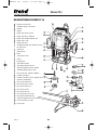
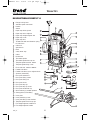
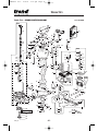
DESCRIPTION OF PARTS T10
A Plunge locking lever
B Variable speed control dial
C Handle
D Switch
E Depth stop locking knob
F Depth stop micro adjuster
G Depth stop height adjuster dial
H Depth stop scale
I Depth stop lens
J
Thumb knob with anti-vibration spring
for side fence
K
Collet nut
L
Spindle lock
M
Base
N
3-way turret stop
O
Collet
P
Knurled nut
Q
Threaded spindle
R
Threaded spindle cap nut
S
Template guide bush dia. 30mm
T
Template guide fixing screw
U
Fence rods dia. 10mm x 360mm
V
Parallel side fence
W
Parallel side fence micro adjuster knob
X
Spanner (22mm A/F)
Y
Dust spout 35mm dia.
Z
Dust spout fixing screws
AA
Dust spout fixing nut
AB
Dust spout insert
AC
Dust spout top clip
AD
Dust spout top clip screw
AE Dust Spout underside clip
AF Template guide bush line-up pin
AG Inner plate fixing screws
AH Inner plate
MANU-T10 v2.0 2/2/05 2:31 pm Page 6
B&D_47

T10 & T11
-7-
4
R
B
C
P
Q
I
H
A
E
F
X
N
U
M L
J
K
G
AD
AF
AC
AA
AB
AG
AL
AM
Z
W
V
Y
O
S
T
AK
AH
AJ
AI
D
AE
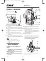
DESCRIPTION OF PARTS T11
A Plunge locking lever
B Variable speed control dial
C Handle
D Switch
E Depth stop locking knob
F Depth stop micro adjuster
G Depth stop height adjuster dial
H Depth stop scale
I Depth stop lens
J
Thumb knob with anti-vibration spring
for side fence
K
Collet nut
L
Spindle lock
M
Base
N
3-way turret stop
O
Collet
P
Knurled nut
Q
Threaded spindle
R
Threaded spindle hex cap nut
S
Template guide bush dia. 30mm
T
Template guide fixing screw
U
Fence rods dia. 10mm x 360mm
V
Parallel side fence
W
Parallel side fence micro adjuster knob
X
Spanner (22mm A/F)
Y
Dust spout 35mm dia.
Z
Dust spout fixing screws
AA
Dust spout fixing nut
AB
Dust spout insert
AC
Dust spout top clip
AD
Dust spout top clip screw
AE
Dust spout underside clip
AF
Quick release jig & table aperture
AG
Clamp guide system fitting
AH
Inner plate
AI
Inner plate fixing screw
AJ
Inner plate fixing screw washers
AK
Template guide bush line-up pin
AL
Fine height adjuster handle dial
AM
Fine height adjuster handle
MANU-T10 v2.0 2/2/05 2:31 pm Page 7
B&D_47

T10 & T11
-8-
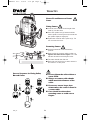
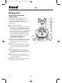
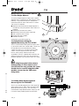
ASSEMBLY & ADJUSTMENT
I Set the measuring lens (5) to a round figure
or zero.
I Adjust the depth of cut using the knob (6) and
the measuring lens (5).
The distance between the top of the revolving
depth stop and the bottom of the depth stop is
the required depth of cut.
I Tighten the knob (2).
The rotating turret stop screws can be used
for pre-setting up to three depths of cut.
Their
height can be adjusted using a screwdriver
(7) and an 8mm A/F spanner (8).
1
7
3
8
By turning the turret stop, three depth settings
can be quickly made.
4
5
4
2
3
1
6
I Never make adjustments
when the router is running or
plugged in.
I Deep cuts should always be
routed in several passes.
If the depth of cut needs re-adjustment, it is
recommended to use the depth stop micro
adjuster.
I Adjust the depth of cut using the depth stop
micro adjuster (3). One turn corresponds to
approximately 1mm.
I Read the depth of cut using the measuring
lens (5) and scale.
I Adjust the depth of cut to the millimetre using
the knob (6).
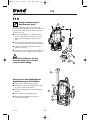
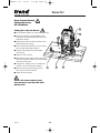
ON
OFF
I
O
O
N
O
F
F
I
O
Switching On & Off
I On; pull the switch up.
I Off; press the switch down.
Adjusting the Depth of Cut
I Place the machine with cutter fitted on to the
workpiece.
I Pre-set the 3-way turret stop (1) as required.
I Undo the thumb knob (2) for securing the depth
stop (3).
I Lift up the plunge locking lever (4) for fixing the
depth.
I Lower the machine slowly until the cutter
touches the workpiece and secure it with the
locking lever.
I
Rotate the knob (6) until the depth stop micro
adjuster (3) touches the revolving depth stop (1).
MANU-T10 v2.0 2/2/05 2:31 pm Page 8
B&D_47

T10 & T11
-9-
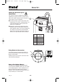
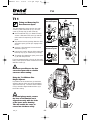
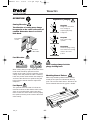
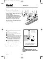
How to Fit and Remove a Router
Cutter
Fitting Cutters
I Insert at least
3
/4 of the shank length of the
cutter (1) into the collet.
I Press the spindle lock (2) forward until the
router spindle is locked (you may need to turn
the spindle slightly to engage it).
I Tighten the collet nut with a spanner (3). Do
not use excessive force.
Removing Cutters
I Undo the 22mm A/F collet nut with the
spanner.
I Keep turning the spanner until the collet nut
tightens and then loosens again. This is the
fail-safe mechanism releasing the collet.
I The cutter should now slide out.
I Each time you finish using a cutter, remove it
and store it in a safe place.
2
3
1
CLICK
(2)
(3)
(1)
Correct Sequence for Fitting Collet,
Nut and Cutter
I Do not tighten the collet without a
cutter fitted.
I Always use cutters with shanks
which match the diameter of the
collet.
I Do not use cutters larger than
45mm unless the router is fitted in
a router table.
I Care should be taken when
removing cutter to avoid cuts to
fingers.
4
MANU-T10 v2.0 2/2/05 2:31 pm Page 9
B&D_47

T10 & T11
-10-
5
1
Setting the Electronic Speed
Control Dial
The speed is infinitely variable from 8,000 to
20,000 rpm using the electronic speed control
dial (1) for uniform cutting results in all types of
wood, plastics and in aluminium.
I Turn the electronic speed control dial to the
required level. The dial is numbered from 1 to
5 and corresponds to router speeds from
8,000 rpm to 20,000 rpm.
I Generally, use the lower settings for large
diameter cutters and the higher settings for
small diameter cutters. The correct setting will
also depend on the density of the material,
depth of cut and feed speed of the router, as
severe loss of rpm denotes motor overload.
Dial Router
No. Speed
1 8,000 rpm
2 12,000 rpm
3 16,000 rpm
4 18,000 rpm
5 20,000 rpm
115mm
75mm
15mm
M6
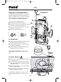
Fixing Points for Accessories
The router has three threaded holes M6 in its
base that allow fitting of accessories and also
fitting to router tables.
A whole range of accessories are shown in the
Trend Routing Catalogue.
Using a Fine Height Adjuster
The T10 has an optional fine height adjuster
accessory Ref. FHA/003 and the T11 has a built
in fine height adjuster. These should be used
when fine height adjustment of the cutter is
required. This is especially recommended when
using dovetail jigs or router tables.
MANU-T10 v2.0 2/2/05 2:32 pm Page 10
B&D_47

T10
-11-
4
1
5
6
2
4
3
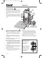
Fitting the T10 Fine Height Adjuster
Optional Accessory Ref. FHA/003
I Plunge router and lock lever (6) down.
I Remove hex cap (5) nut from threaded stud
(3), using a 19mm A/F spanner.
I Remove knurled ring nut (4) from threaded
stud (3).
I Place washer (2) on threaded stud.
I Thread on main adjuster rod (1) for at
least 25mm of thread.
Fitting and Removing T10
Dust Extractor Spout
The dust extraction spout consists of a main
section (1) with underside clip (7), an insert cover
(2), top clip (5) with screw (6), two main screws
(3) & two nuts (4).
I Check underside clip (7) is fitted into main
section. Slide the insert cover (2) onto the
main section if required (1) and click into
place.
I Fit nuts (4) into main body. Place spout into
base of router and secure with two screws (3).
I Connect a dust extractor hose to the dust
extraction spout (1).
I Loosen the screw in the top of the router and
fit the top clip (5) as shown using screw (6).
35mm
3
2
4
1
7
6
5
Whenever possible use the dust
extraction spout with a suitable
extractor when routing.
T10
MANU-T10 v2.0 2/2/05 2:32 pm Page 11
B&D_47

T11
-12-
2
1
8
5
7
3
4
6
T11
only
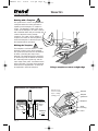
Fitting Template Guide Bush
and Inner Plate
The routers have a unique built-in line up
system for the template guide bush. This
system ensures that the guide bush is exactly
concentric to the router cutter to ensure
accurate work.
I Turn the router upside down.
I Fit inner plate (2) into the recess in the router
base plate (1). For T10 the bushes on the
inner plate must be towards the router motor.
For T11 the raised side of the inner plate must
be away from router base. Loosely fit the two
pan head machine screws (3) through the
inner plate and into the tapped holes. For
T11 also use split spring washers (4) under
the head of the machine screws (3).
DO NOT TIGHTEN SCREWS.
I Fit the 30mm template guide bush (6) to the
inner plate (2). Fit guide bush with the two M5
countersink machine screws (7). Tighten
these screws.
I The line up pin (5) is stepped for 12mm and
1
/2” collet (8) sizes. (For the
1
/2” collet simply
push the line up pin further down into the
1
/2”
collet).
I Fit line up pin (5) into the
1
/2” collet (8) (or
12mm depending on the size fitted) in the
router, lightly tighten collet nut to hold the line
up pin (5).
I Release plunge lever and gently depress
base until line up pin (5) projects through the
30mm guide bush (6).
I Once in line, tighten the pan head machine
screws (3) with a flat screwdriver.
T10 & T11
MANU-T10 v2.0 2/2/05 2:32 pm Page 12
B&D_47

T11
-13-
4
3
2
4
T11
Using the T11 Without Fine
Height Adjuster
In portable use the knurled nut (2) should be
wound to the top of the stud and hand tighten
against the hex cap. The base of the knurled
nut (4) should be aligned with the forks (3) in
the router casting.
In normal plunge mode, ensure
the base of the knurled nut is
aligned correctly with the forks
of the lower motor housing.
This will enable the cutter to
retract into the base safely.
Fitting and Removing T11
Dust Extractor Spout
The dust extraction spout consists of a main
section (1) with underside clip (7), an insert
cover (2) and top clip (5) with screw (6).
I Check underside clip (7) is fitted into main
section. Slide the insert cover (2) onto the
main section if required (1) and click into
place.
I Clip into the base by pushing down the dust
extraction spout (1) until clips engage in the
recess.
I Connect a dust extractor hose to the dust
extraction spout (1).
I Loosen the screw in the top of the router and
fit the top clip (5) as shown using screw (6).
I To remove dust extraction spout, push spout
(1) to side and pivot out.
For more permanent fixing, fit nuts (4) into main
body, place spout into base of router and secure
with two screws (3).
Fitting Dust
Extractor Spout
Whenever possible use the dust
extraction spout with a suitable
extractor when routing.
B
A
B
A
C
Removing Dust
Extractor Spout
3
2
4
1
7
6
5
35mm
MANU-T10 v2.0 2/2/05 2:32 pm Page 13
B&D_47

5
10
9
7
1
.
0
1
.5
0
T11
-14-
Fitting the T11 Fine Height Adjuster
The fine height adjuster for the T11 can be used
portably or when the router is held inverted in a
table. If a suitable size access hole is drilled into
the router table top, the height adjustment can
also be adjusted from above the table top.
To set up for fine height adjustment:
I Plunge router and lock lever down (1).
I Rotate the knurled nut (2) down the stud until it
is close to the router casting forks (3).
I Align the base of the knurled nut (4) so that it
will locate in the forks (3).
I Release plunge locking lever (1).
For Portable Use
I Place the fine height adjuster handle (5) onto
the top threaded spindle hex nut (6).
I Rotate handle clockwise to raise motor body
and reduce cutter depth.
I Rotate handle anti-clockwise to lower motor
body and increase cutter depth.
One revolution corresponds to 1.5mm. The
height adjuster handle dial (7) can be reset to
zero.
For Router Table Use
I Ensure router is fitted into the router table (10),
see opposite page.
I Place fine height adjuster handle (5) through
router table cutter hole onto bottom threaded
spindle hex nut (9).
I Rotate handle clockwise to raise motor body
and raise cutter height.
I Rotate handle anti-clockwise to lower motor
body and lower cutter height.
One revolution corresponds to 1.5mm. The
height adjuster handle dial (7) can be reset to
zero.
4
5
4
2
3
1
7
6
Portable Use
68mm
36mm
MANU-T10 v2.0 2/2/05 2:32 pm Page 14

-15-
T11
5
4
3
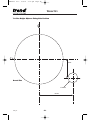
Modification of User Router Table for
T11 Fine Height Adjuster
To use fine height adjuster in table mode a 20mm
diameter hole is required to be drilled into the router
table top. To position the hole it is advisable to
remove the phenolic base slider of the T11 router
and use it as a template.
I Mark the hole for the handle height adjuster in
the table top using the phenolic base slider as a
template.
I Remove the phenolic base slider.
I Mark with a punch the centre of the hole.
I Drill a pilot hole in the centre.
I Enlarge the hole to 20mm.
I Remove any burrs.
A template is provided on page 28.
T11 Quick Release Fixing Kit
Optional Accessory Ref. T11/JT/KIT
The T11 Quick Release Fixing Kit uses three cams
(1) to lock the router into a router table. The kit can
be retro-fitted to user-made tables by drilling
suitable size holes in a set pattern into the table
surface. The kit comprises three cams, three
bosses, three springs and three nut & bolt
assemblies. The kit is supplied with instructions for
drilling and using the cams. The cams locate into
the three apertures (2) in the base of the T11 router.
When using large panel raiser cutters,
making deeps or if the router is to be
used inverted for long periods, the router
should also be secured using three M6
machine screws into the TBC router
fixing holes.
T11 Clamp Guide System Optional
Accessory Ref. T11/CGS/KIT
The T11 has two M6 tapped holes in the upper face
of the router base (3), which will accept the Clamp
Guide System accessory (4). The accessory is
used with the Clamp Guide System clamps (5) and
is used to create parallel grooves and trenches.
2
Table Use
Top View
MANU-T10 v2.0 2/2/05 2:32 pm Page 15
B&D_47

T10 & T11
-16-
Step One
Plunge down and lock the
motor carriage, by
depressing the plunge
locking lever.
Step Two
Carry out the routing
operation.
Step Three
Release the plunge locking
lever and the motor carriage
returns to the normal
position.
Sequence of plunging
Feed Direction
When routing along an edge, the direction of the
router travel should be against that of the
rotation of the cutter. This will create the correct
cutting action and prevent the cutter ‘snatching’.
It will also pull the router towards the workpiece
and hence the side-fence or guide bearing will
be less likely to wander from the edge of the
workpiece.
Feed Speed
The speed at which the cutter is fed into the
wood must not be too fast that the motor slows
down, or too slow that the cutter leaves burn
marks on the face of the wood. Practice judging
the speed by listening to the sound of the motor
when routing.
OPERATION
Cutting Direction
The direction of routing must always
be opposite to the cutter’s direction of
rotation. Otherwise there is a risk of
kick-back.
Moulding Natural Timbers
When edge moulding natural timbers, always
mould the end grain first, followed by the long
grain. This ensures that if there is ‘breakout’, this
will be removed when the long grain is routed.
Feed direction
of router
Direction of
cutter rotation
2
1
4
3
When routing always lock the
plunge locking lever.
MANU-T10 v2.0 2/2/05 2:32 pm Page 16
B&D_47

T10 & T11
-17-
A
B
7
9
14 8
23
6
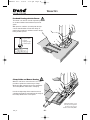
Side-Fence Routing
The side-fence is used to guide the router when
moulding, edge profiling or rebating the edge of
the workpiece or when routing grooves and slots
in the centre of the workpiece, parallel to the
edge.
The edge of the workpiece must be straight and
true. The cheeks are adjustable and should be
set ideally with a 3–4mm gap each side of the
cutter.
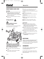
C
D
When starting the cut, keep
the pressure on the front
cheek (C) until the back
cheek contacts the
workpiece edge.
At the end of the cut, keep
pressure on the back cheek
(D) until the cut is finished.
This will prevent the router
cutter swinging in at the end
of the wor
kpiece and
‘nipping’ the corner.
Fitting and using the Side Fence
I Make sure the thumb knobs (3) are fully
released. Slide the guide rods (1) into the
routing base (2) and tighten the thumb knobs
(3).
I Adjust the side-fence (4) to the required
distance and clamp in place with the thumb
knobs (3).
I Then lower the cutter height until the cutter is
just above the workpiece.
I Fine adjustments are possible by slackening
the underside locking knob (8), adjusting the
micro-adjustment knob (6) and securing it
again with the knob (8). One revolution of the
micro-adjustment knob (6) equals 1.0mm of
side-feed.
I Lower the cutter onto the workpiece and set
the cutter height by raising the depth stop (7)
the required distance.
I Switch on the router and when the cutter
reaches full speed, gently lower the cutter into
the workpiece and lock the plunge.
I Feed along the timber, keeping sideways
pressure (A) to ensure the side fence does
not wander away from the workpiece edge
and downward pressure on the inside hand
(B) to prevent the router from tipping.
I When finished, raise the router, secure with
the plunge locking lever (9) and switch off.
MANU-T10 v2.0 2/2/05 2:32 pm Page 17
B&D_47
La pagina si sta caricando...
La pagina si sta caricando...
La pagina si sta caricando...
La pagina si sta caricando...
La pagina si sta caricando...
La pagina si sta caricando...
La pagina si sta caricando...
La pagina si sta caricando...
La pagina si sta caricando...
La pagina si sta caricando...
La pagina si sta caricando...
La pagina si sta caricando...
La pagina si sta caricando...
La pagina si sta caricando...
-
 1
1
-
 2
2
-
 3
3
-
 4
4
-
 5
5
-
 6
6
-
 7
7
-
 8
8
-
 9
9
-
 10
10
-
 11
11
-
 12
12
-
 13
13
-
 14
14
-
 15
15
-
 16
16
-
 17
17
-
 18
18
-
 19
19
-
 20
20
-
 21
21
-
 22
22
-
 23
23
-
 24
24
-
 25
25
-
 26
26
-
 27
27
-
 28
28
-
 29
29
-
 30
30
-
 31
31
-
 32
32
-
 33
33
-
 34
34


Trend T10 Original Instructions Manual
- Categoria
- Utensili elettrici
- Tipo
- Original Instructions Manual
- Questo manuale è adatto anche per
in altre lingue
- English: Trend T10
Altri documenti
-
Black & Decker KW1200E Manuale utente
-
Black & Decker KW1600E Manuale utente
-
BLACK DECKER KW1600E Manuale del proprietario
-
-
Dremel 335 Manuale del proprietario
-
BLACK DECKER kw 900 e Manuale del proprietario
-
-
 Status RH1800 Manuale del proprietario
-
Triton Tools TDJ 600 Manuale del proprietario
-
Dremel 231 Manuale del proprietario
