
4
1
2
3
1
2
3
7
8
9
10 11 12 13
5
4
3
2
1
5
4
5
6
Switch matrix per presentazioni True 4K 4 x 2 VP1420
www.aten.com
Conmutador de matriz de presentación 4K real VP1420 4 x 2
www.aten.com
VP1420 4 x 2 True 4K Präsentation Matrix Switch
www.aten.com
Commutateur matriciel de présentation True 4K 4 x 2 VP1420
www.aten.com
© Copyright 2019 ATEN
®
International Co., Ltd.
ATEN and the ATEN logo are trademarks of ATEN International Co., Ltd. All rights reserved. All
other trademarks are the property of their respective owners.
Part No. PAPE-1223-R50G Printing Date: 06/2019
4 x 2 True 4K Presentation Matrix Switch
Quick Start Guide
VP1420
VP1420 4 x 2 True 4K Presentation Matrix Switch
www.aten.com
ATEN VanCryst
™
B
Package Contents
1 VP1420 4 x 2 True 4K Presentation Matrix Switch
1 IR Receiver
1 IR Remote Control
2 3-pole Terminal Blocks
2 5-pole Terminal Blocks
1 Power Adaptor
1 User Instructions
Hardware Installation
Front View
Rear View
IR Remote Control
A
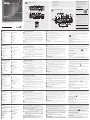
Hardware Review
A
Hardware Review
Front View
1
Display Selection Pushbuttons
2
Source Selection Pushbuttons
3
Mode Pushbutton
Rear View
1
Grounding Terminal
2
Ethernet Port
3
IR Receiver Port
4
RS-232 Serial Port
5
Contact In
6
LED Out
7
Audio In
8
Audio Out
IR Remote Control
1
On/Off
2
Source
3
Display
6
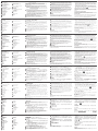
(Optional) To control the VP1420 via a contact closure switch, connect
the contact closure switch to the Contact In and LED Out ports using the
provided 5-pole Terminal Blocks.
7
(Optional) To confi gure the unit’s settings via RS-232 serial commands,
connect a hardware controller, e.g. ATEN Control Box, to the RS-232 Serial
Port using the provided 3-pole Terminal Block.
8
(Optional) To allow access to the web interface, use an Ethernet cable to
connect the Ethernet port of the unit to a network switch.
9
(Optional) To control the VP1420 using an IR remote control, connect the IR
receiver to the IR Receiver Port.
10
Plug the power adapter to the Power Jack. Optionally use the cable tie slot
and a cable tie to hold the power cable in place.
11
Press the Power Pushbutton to power on the unit.
12
Power on all the connected devices.
Operation
You can operate the unit using the front-panel pushbuttons, IR remote control,
RS-232 serial controller, or the web interface. For detailed instructions, see the
user manual.
Front-panel Pushbuttons
•
To select a source, press the Display Selection Pushbutton, and then press the
Source Selection Pushbutton that corresponds to the input you wish to display. The
selected source pushbutton lights green and the selected display lights orange.
• To lock or unlock the front-panel pushbuttons, press and hold the Mode
Pushbutton for fi ve seconds. When the front panel is locked, the lock icon
(
) lights red.
IR Remote Control Unit
To select a source, press the Display Button to focus a display, and then press
the Source Button that corresponds to the source you wish to output.
RS-232 Serial Interface
The built-in bi-directional RS-232 serial interface allows system control through
a high-end controller, such as a computer.
Web Interface
The web interface allows you to confi gure system settings. Upon fi rst
login, use the default IP address 192.168.0.60 and the default credentials
(administrator/password).
Note: The Volume Up and Volume Down buttons are not applicable for the VP1420.
B
Hardware Installation
Refer to the installation diagram above and the instructions below to connect
devices to the VP1420.
1
Use a grounding wire to ground the unit by connecting one end to the
grounding terminal, and the other end to a suitable grounded object.
Note: Do not omit this step. Proper grounding helps prevent damage to
the unit from power surges or static electricity.
2
Connect the unit to video sources.
• To connect a VGA source, use a VGA cable and a stereo audio cable to
connect the source to the VGA In and the Stereo Audio In port respectively.
• To connect an HDMI-enabled source, use an HDMI cable to connect the device
to the HDMI In port. You can connect up to three HDMI-enabled sources.
3
Use an HDMI cable to connect the unit to at least one HDMI-enabled display.
4
(Optional) Connect an audio source device, such as a media player to the
Audio In port.
5
(Optional) Connect an active speaker to the Audio Out port using the
provided 3-pole Terminal Block.
4
1
2
3
3
7
8
9
10
5
6
Internet/
LAN
Media Player
A
B
9
Cable Tie Slot
10
Power Jack
11
Source 1
- VGA In
- Stereo Audio In
12
Source 2, 3, 4
- HDMI In
13
HDMI Out
4
Mute Pushbutton
5
Power Pushbutton
4
Mute
5
Mode
Support and Documentation Notice
All information, documentation, fi rmware,
software utilities, and specifi cations contained in
this package are subject to change without prior
notifi cation by the manufacturer.
To reduce the environmental impact of our
products, ATEN documentation and software can
be found online at
http://www.aten.com/download/
Technical Support
www.aten.com/support
이 기기는 업무용(A급) 전자파적합기기로서 판매자 또는 사용자는 이 점을
주의하시기 바라며, 가정외의 지역에서 사용하는 것을 목적으로 합니다.
Scan for
more information
EMC Information
FEDERAL COMMUNICATIONS COMMISSION INTERFERENCE
STATEMENT:
This equipment has been tested and found to comply with the limits
for a Class A digital device, pursuant to Part 15 of the FCC Rules.
These limits are designed to provide reasonable protection against
harmful interference when the equipment is operated in a commercial
environment. This equipment generates, uses, and can radiate radio
frequency energy and, if not installed and used in accordance with
the instruction manual, may cause harmful interference to radio
communications. Operation of this equipment in a residential area
is likely to cause harmful interference in which case the user will be
required to correct the interference at his own expense.
FCC Caution: Any changes or modifi cations not expressly approved by
the party responsible for compliance could void the user's authority to
operate this equipment.
Warning: Operation of this equipment in a residential environment
could cause radio interference.
This device complies with Part 15 of the FCC Rules. Operation is subject
to the following two conditions:(1) this device mat not cause harmful
interference, and(2) this device must accept any interference received,
including interference that may cause undesired operation.
Important. Before proceeding, download the Installation and
Operation Manual by visiting the website, www.aten.com and
navigating to the product page. The manual includes important
warnings, loading specifi cations and grounding instructions.
A
Aperçu du matériel
Vue de devant
1
Boutons de sélection de l'affi chage
2
Boutons de sélection de la source
3
Bouton-poussoir de mode
Vue de derrière
1
Borne de mise à la terre
2
Port Ethernet
3
Port récepteur IR
4
Port série RS-232
5
Entrée contact
6
Sortie LED
7
Entrée audio
8
Sortie audio
Télécommande IR
1
Marche/Arrêt
2
Source
3
Affi chage
5
(Facultatif) Connectez un haut-parleur actif au port de sortie audio en utilisant
le bornier à 3 pôles fourni.
6
(Facultatif) Pour contrôler le VP1420 via un interrupteur à contact sec,
connectez l'interrupteur à contact sec aux ports d’entrée contact et de
sortie LED en utilisant les borniers à 5 pôles fournis.
7
(Facultatif) Pour confi gurer les paramètres de l’unité via les commandes
série RS-232, connectez un contrôleur matériel, par ex. un boîtier de
contrôle ATEN, au port série RS-232 en utilisant le bornier à 3 pôles fourni.
8
(Facultatif) Pour permettre l’accès à l’interface Web, utilisez un câble Ethernet
afi n de connecter le port Ethernet de l’unité à un commutateur réseau.
9
(Facultatif) Pour contrôler le VP1420 en utilisant une télécommande IR,
connectez le récepteur IR au port du récepteur IR.
10
Branchez l’adaptateur secteur sur la prise d’alimentation. Utilisez, de
manière facultative, l’emplacement de l’attache-câble et un attache-câble
pour maintenir le câble d’alimentation en place.
11
Appuyez sur le bouton-poussoir d’alimentation de l’unité.
12
Allumez tous les appareils connectés.
Fonctionnement
Vous pouvez utiliser l’unité à l’aide des boutons-poussoirs du panneau avant,
de la télécommande IR, du contrôleur série RS-232 ou de l’interface Web. Pour
des instructions détaillées, consultez le manuel d'utilisation.
Boutons du panneau avant
• Pour sélectionner une source, appuyez sur le bouton de sélection d'affi chage,
puis appuyez sur le bouton de sélection de source correspondant à l'entrée
que vous souhaitez affi cher. Le bouton-poussoir de la source sélectionnée
s’allume en vert et l’écran sélectionné s’allume en orange.
•
Pour verrouiller ou déverrouiller les boutons-poussoirs du panneau avant, appuyez
et maintenez le bouton-poussoir du mode pendant cinq secondes. Lorsque le
panneau avant est verrouillé, l'icône de verrouillage (
) s'allume en rouge.
Télécommande IR
Pour sélectionner une source, appuyez sur le bouton Display (Affi chage) pour
cibler un affi chage, puis appuyez sur le bouton Source correspondant à la
source que vous souhaitez affi cher.
Interface série RS-232
L'interface série bidirectionnelle RS-232 intégrée permet de contrôler le sys-
tème via un contrôleur haut de gamme tel qu'un ordinateur.
Interface Web
L’interface Web vous permet de confi gurer les paramètres système. Lors de la
première connexion, utilisez l’adresse IP par défaut 192.168.0.60 et les infor-
mations de connexion par défaut (administrator/password).
Remarque : Les boutons pour augmenter/réduire le volume ne sont pas
applicables au VP1420.
B
Installation du matériel
Référez-vous au schéma d’installation ci-dessus et aux instructions ci-dessous
pour connecter les appareils au VP1420.
1
Utilisez un fi l de mise à la terre pour relier l'unité en connectant une extrémité à
la borne de mise à la terre et l'autre extrémité à un objet mis à la terre approprié.
Remarque : Ne négligez pas cette étape. Une mise à la terre appropriée
aide à prévenir les dommages à l'appareil due aux surtensions
ou à l'électricité statique.
2
Connectez l’unité aux sources vidéo.
• Pour connecter une source VGA, utilisez un câble VGA et un câble audio
stéréo pour connecter la source à l’entrée VGA et au port d’entrée audio
stéréo respectivement.
• Pour connecter une source compatible HDMI, utilisez un câble HDMI
pour connecter l’appareil au port d’entrée HDMI. Vous pouvez connecter
jusqu’à trois sources compatibles HDMI.
3
Utilisez un câble HDMI pour connecter l’unité à au moins un écran compatible HDMI.
4
(Facultatif) Connectez un appareil source audio, tel qu’un lecteur multimédia
au port d’entrée audio.
9
Fente de l'attache de câbles
10
Fiche d'alimentation
11
Source 1
- Entrée VGA
- Entrée audio stéréo
12
Source 2, 3, 4
- Entrée HDMI
13
Sortie HDMI
4
Bouton-poussoir muet
5
Bouton d'alimentation
4
Muet
5
Mode
A
Hardwareübersicht
Ansicht von vorne
1
Anzeigeauswahl-Drucktasten
2
Quellenauswahl-Drucktasten
3
Modusdrucktaste
Ansicht von hinten
1
Erdungsanschluss
2
Ethernet Anschluss
3
IR Empfangsanschluss
4
RS-232 serieller Anschluss
5
Kontakt Eingang
6
LED Ausgang
7
Audio Eingang
8
Audio Ausgang
IR Fernbedienung
1
Ein/Aus
2
Quelle
3
Anzeige
Hinweis: Die Tasten Lauter und Leiser gelten nicht für den VP1420.
6
(Optional) Um den VP1420 über einen Kontaktschließschalter zu steuern,
verbinden Sie den Kontaktschließschalter über die mitgelieferten 5-poligen
Anschlussblöcke mit den Anschlüssen Kontakt Eingang und LED Ausgang.
7
(Optional) Um die Einstellungen des Geräts über serielle RS-232 Befehle zu
konfi gurieren, schließen Sie einen Hardware Controller, z.B. die ATEN
Kontrollbox, über den mitgelieferten 3-poligen Anschlussblock an den
seriellen RS-232 Anschluss an.
8
(Optional) Um den Zugriff auf die Webschnittstelle zu ermöglichen,
verwenden Sie ein Ethernet-Kabel, um den Ethernet-Anschluss des Geräts
mit einem Netzwerk Switch zu verbinden.
9
(Optional) Um den VP1420 mit einer IR-Fernbedienung zu steuern,
verbinden Sie den IR-Empfänger mit dem IR-Empfängeranschluss.
10
Schließen Sie das Netzteil an die Netzbuchse an. Verwenden Sie optional
den Kabelbinderschlitz und einen Kabelbinder, um das Netzkabel an seinem
Platz zu halten.
11
Drücken Sie die Ein-/Aus-Taste, um das Gerät einzuschalten.
12
Schalten Sie alle angeschlossenen Geräte ein.
Bedienung
Sie können das Gerät über die Tasten an der Vorderseite, die IR-Fernbedienung,
den seriellen RS-232 Controller oder die Webschnittstelle bedienen. Detaillierte
Informationen fi nden Sie in der Bedienungsanleitung.
Drucktasten an der Vorderseite
• Um eine Quelle auszuwählen, drücken Sie die Drucktaste zur Auswahl des
Bildschirms und dann die Drucktaste zur Auswahl der Quelle, die dem an-
gezeigten Eingang entspricht. Die Taste für die ausgewählte Quelle leuchtet
grün und die ausgewählte Anzeige leuchtet orange.
• Um die Drucktasten auf der Vorderseite zu sperren oder zu entriegeln, halten
Sie die Modus Taste fünf Sekunden lang gedrückt. Wenn die Vorderseite
verriegelt ist, leuchtet das Schloss-Symbol ( ) rot.
IR-Fernbedienung
Um eine Quelle auszuwählen, drücken Sie die Anzeige-Taste, um eine Anzeige
zu fokussieren, und drücken Sie dann die Quelle-Taste, die der Quelle ent-
spricht, die Sie ausgeben möchten.
Serielle RS-232 Schnittstelle
Die integrierte bidirektionale serielle RS-232 Schnittstelle ermöglicht die Sy-
stemsteuerung über einen High-End-Controller, wie z.B. einen Computer.
Webschnittstelle
Über die Webschnittstelle können Sie Systemeinstellungen konfi gurieren. Ver-
wenden Sie bei der ersten Anmeldung die Standard IP-Adresse 192.168.0.60
und die Standard Anmeldeinformationen (administrator/password).
B
Hardwareinstallation
Lesen Sie das Installationsschema oben und die Anweisungen unten, um
Geräte an das VP1420 anzuschließen.
1
Verwenden Sie ein Erdungskabel, um das Gerät zu erden, indem Sie ein
Ende mit der Erdungsklemme und das andere Ende mit einem geeigneten
geerdeten Objekt verbinden.
Hinweis: Lassen Sie diesen Schritt nicht aus. Eine ordnungsgemäße Erdung
hilft bei der Vermeidung von Schäden am Gerät durch Stromspitzen
oder statischer Elektrizität.
2
Schließen Sie das Gerät an Videoquellen an.
• Um eine VGA-Quelle anzuschließen, verwenden Sie ein VGA-Kabel und
ein Stereo Audiokabel, um die Quelle mit dem VGA-Eingang bzw. dem
Stereo Audioeingang zu verbinden.
• Um eine HDMI-fähige Quelle anzuschließen, verwenden Sie ein HDMI-
Kabel, um das Gerät an den HDMI-Eingang anzuschließen. Sie können
bis zu drei HDMI-fähige Quellen anschließen.
3
Verwenden Sie ein HDMI-Kabel, um das Gerät an mindestens einen HDMI-
fähigen Bildschirm anzuschließen.
4
(Optional) Verbinden Sie ein Audioquellengerät, wie beispielsweise einen
Mediaplayer, mit dem Audioeingang.
5
(Optional) Schließen Sie einen Aktivlautsprecher über den mitgelieferten
3-polige Anschlussblock an den Audioausgang an.
9
Kabelbinder Schacht
10
Netzanschluss
11
Quelle 1
- VGA Eingang
- Stereo Audio-Eingang
12
Quelle 2, 3, 4
- HDMI Eingang
13
HDMI Ausgang
4
Stummschalttaste
5
Ein-/Aus-Drucktaste
4
Ton aus
5
Modus
A
Revisión de hardware
Vista frontal
1
Botones de selección de pantalla
2
Botones de selección de fuente
3
Pulsador de modo
Vista posterior
1
Toma de tierra
2
Puerto Ethernet
3
Puerto receptor IR
4
Puerto serie RS-232
5
Entrada de contacto
6
Salida LED
7
Entrada de audio
8
Salida de audio
Mando a distancia por infrarrojos
1
Encendido/apagado
2
Fuente
3
Pantalla
Nota: Los botones de subir y bajar el volumen no son aplicables para al modelo VP1420.
6
(Opcional) Para controlar el VP1420 a través de un interruptor de cierre
de contacto, conecte el interruptor de cierre de contacto a los puertos de
entrada de contacto y salida LED utilizando los bloques de terminales de 5
polos suministrados.
7
(Opcional) Para ajustar la confi guración de la unidad a través de comandos
serie RS-232, conecte un controlador de hardware (p. ej., una caja de
control ATEN) al puerto serie RS-232 utilizando el bloque de terminales de
3 polos suministrado.
8
(Opcional) Para permitir el acceso a la interfaz web, utilice un cable Ethernet
para conectar el puerto Ethernet de la unidad a un conmutador de red.
9
(Opcional) Para controlar el VP1420 mediante un mando a distancia por
infrarrojos, conecte el receptor de infrarrojos al puerto del receptor de infrarrojos.
10
Conecte el adaptador de alimentación a la toma de alimentación. También
puede utilizar una abrazadera para cables y la ranura correspondiente para
mantener el cable de alimentación en su sitio.
11
Pulse el botón de encendido para encender la unidad.
12
Encienda todos los dispositivos conectados.
Funcionamiento
Puede manejar la unidad a través de los botones del panel delantero, el mando
a distancia por infrarrojos, el controlador serie RS-232 o la interfaz web. Para
obtener instrucciones detallada, consulte el manual del usuario.
Pulsadores del panel frontal
• Para seleccionar una fuente, pulse el botón de selección de pantalla y, a
continuación, pulse el botón de selección de fuente que corresponda a la
entrada que desea visualizar. El botón de la fuente seleccionada se ilumina
en verde y la pantalla seleccionada se ilumina en naranja.
• Para bloquear o desbloquear los botones del panel frontal, mantenga
presionado el pulsador de modo durante cinco segundos. Cuando el panel
frontal está bloqueado, el icono del candado (
) se ilumina en rojo.
Unidad de control remoto IR
Para seleccionar una fuente, presione el botón de visualización para enfocar
una pantalla y, a continuación, presione el botón de fuente que corresponda a
la fuente que desea mostrar.
Interfaz serie RS-232
La interfaz serie bidireccional incorporada RS-232 permite el control del sistema
a través de un controlador de gama alta, como un ordenador
Interfaz web
La interfaz web le permite confi gurar el sistema. Tras iniciar sesión por primera
vez, utilice la dirección IP predeterminada 192.168.0.60 y los credenciales
predeterminados (administrator/password).
B
Instalación de hardware
Consulte el diagrama de instalación anterior y las instrucciones que se incluyen
a continuación para conectar los dispositivos al VP1420.
1
Utilice un cable de tierra para conectar la unidad a tierra conectando un
extremo al terminal de tierra y el otro extremo a un objeto conectado a
tierra correctamente.
Nota: No omita este paso. Una conexión correcta a tierra protege a la
unidad de la electricidad estática y de las subidas de tensión.
2
Conecte la unidad a las fuentes de vídeo.
• Si desea conectar una fuente VGA, utilice un cable VGA y un cable de
audio estéreo para conectar la fuente a la entrada VGA y al puerto de
entrada de audio estéreo respectivamente.
• Si desea conectar una fuente compatible con HDMI, utilice un cable HDMI
para conectar el dispositivo al puerto de entrada HDMI. Puede conectar
hasta tres fuentes compatibles con HDMI.
3
Utilice un cable HDMI para conectar la unidad al menos a una pantalla
compatible con HDMI.
4
(Opcional) Conecte un dispositivo de fuente de audio, como un reproductor
multimedia, al puerto de entrada de audio.
5
(Opcional) Conecte un altavoz activo al puerto de salida de audio utilizando
el bloque de terminales de 3 polos suministrado.
9
Ranura de abrazadera para cables
10
Conector de alimentación
11
Fuente 1
- Entrada VGA
- Entrada de audio estéreo
12
Fuente 2, 3, 4
- Entrada HDMI
13
Salida HDMI
4
Pulsador Silencio
5
Botón de encendido
4
Silencio
5
Modo
A
Descrizione hardware
Vista anteriore
1
Selezione pulsanti Display
2
Pulsanti di selezione della sorgente
3
Pulsante push modalità
Vista posteriore
1
Terminale di messa a terra
2
Porta Ethernet
3
Porta ricevitore IR
4
Porta seriale RS-232
5
Ingresso contatto
6
Uscita LED
7
Ingresso audio
8
Uscita audio
Telecomando IR
1
On/Off
2
Sorgente
3
Display
6
(Opzionale) Per controllare il VP1420 tramite un interruttore di chiusura del
contatto, collegare l'interruttore di chiusura del contatto alle porte Ingresso
contatto e Uscita LED usando i blocchi terminali a 5 poli in dotazione.
7
(Opzionale) Per confi gurare le impostazioni dell'unità tramite i comandi seriali
RS-232, collegare il controller hardware, ad esempio una Scatola di controllo
ATEN, alla porta seriale RS-232 usando il blocco terminale a 3 poli in dotazione.
8
(Opzionale) Per consentire l'accesso all'interfaccia web, usare il cavo
Ethernet per collegare la porta Ethernet dell'unità a uno switch di rete.
9
(Opzionale) Per collegare il VP1420 usando un telecomando IR, collegare il
ricevitore IR alla porta Ricevitore IR.
10
Collegare l'adattatore di alimentazione al jack di alimentazione. È anche possibile
usare lo slot fermacavi e un fermacavi per tenere il cavo di alimentazione in posizione.
11
Premere il pulsante push di accensione per accendere l'unità.
12
Accendere tutti i dispositivi collegati.
Funzionamento
È possibile utilizzare l'unità usando i pulsanti push del pannello frontale,
telecomando IR, controller seriale RS-232 o interfaccia web. Per istruzioni
dettagliate, consultare il manuale dell'utente.
Pulsante pannello anteriore
• Per selezionare una sorgente, premere il pulsante Selezione schermo, quindi
premere il pulsante di selezione Sorgente corrispondente all'entrata che si
desidera visualizzare. I pulsante push sorgente selezionato si accende di colore
verde mentre lo schermo selezionato si accende di arancione.
• Per bloccare o sbloccare i pulsanti push del pannello frontale, tenere premuto
il Pulsante push modalità per cinque secondi. Quando il pannello anteriore è
bloccato, l'icona di blocco ( ) si illumina in rosso.
Unità di telecomando IR
Per selezionare una sorgente, premere il pulsante Display per mettere a fuoco
un display e quindi premere il pulsante Sorgente corrispondente alla sorgente
che si desidera trasmettere.
Interfaccia seriale RS-232
L'interfaccia seriale RS-232 bi-direzionale incorporata consente il controllo del
sistema tramite un controller di fascia alta, ad esempio un computer.
Interfaccia web
L'interfaccia web consente di confi gurare le impostazioni del sistema. Al primo
accesso, usare l'indirizzo IP predefi nito 192.168.0.60 e le credenziali predefi nite
(administrator/password).
Nota: I pulsanti Volume su e Volume giù non sono utilizzabili per VP1420.
B
Installazione hardware
Consultare il diagramma di installazione precedente e le istruzioni di seguito
per collegare i dispositivi al VP1420.
1
Utilizzare un fi lo di messa a terra per mettere a terra l'unità collegando
un'estremità al morsetto di messa a terra e l'altra estremità ad un oggetto idoneo.
Nota: Non ignorare questo passaggio. Una messa a terra corretta aiuta a
evitare danni all'unità derivanti da sbalzi elettrici o elettricità statica.
2
Collegare l'unità alle sorgenti video.
• Per collegare una sorgente VGA, usare il cavo VGA e il cavo audio stereo per
collegare la sorgente all'ingresso VGA e alla porta Ingresso audio stereo.
• Per collegare una sorgente dotata di HDMI, usare un cavo HDMI per
collegare il dispositivo alla porta HDMI. È possibile collegare fi no a tre
sorgenti dotate di HDMI.
3
Usare un cavo HDMI per collegare l'unità ad almeno uno schermo dotato di HDMI.
4
(Opzionale) Collegare un dispositivo sorgente audio, ad esempio un lettore
multimediale alla porta ingresso audio.
5
(Opzionale) Collegare un altoparlante attivo alla porta di uscita audio
usando il blocco terminali a 3 poli in dotazione.
9
Slot fermacavi
10
Connettore di alimentazione
11
Sorgente 1
- Ingresso VGA
- Ingresso audio stereo
12
Sorgente 2, 3, 4
- Ingresso HDMI
13
Uscita HDMI
4
Pulsante push disattiva audio
5
Pulsante di alimentazione
4
Disattiva audio
5
Modalità
VP1420: презентационный матричный коммутатор 4 x 2 с поддержкой полного разрешения 4K
www.aten.com
A
Обзор аппаратного обеспечения
Вид спереди
1
Кнопки для выбора дисплея
2
Кнопки для выбора источника
3
Кнопка выбора режима
Вид сзади
1
Клемма заземления
2
Порт Ethernet
3
Порт инфракрасного ресивера
4
Последовательный порт RS-232
5
Входные контакты
6
Выход на светодиоды
7
Аудиовход
8
Аудиовыход
ИК-пульт ДУ
1
Вкл/Выкл
2
Источник
3
Дисплей
6
(Необязательно) Для управления VP1420 через коммутатор с
замыкающими контактами подключите коммутатор с замыкающими
контактами к портам «Входные контакты» и «Выход на светодиоды»,
используя прилагаемые 5-контактные клеммные колодки.
7
(Необязательно) Для настройки параметров устройства с помощью
команд через последовательный порт RS-232 подключите аппаратный
контроллер, например блок управления ATEN, к 3-контактной клеммной
колодке последовательного порта RS-232.
8
(Необязательно) Для доступа к веб-интерфейсу подключите порт
Ethernet устройства к сетевому коммутатору с помощью кабеля Ethernet.
9
(Необязательно) Для управления VP1420 с помощью ИК-пульта дистан-
ционного управления подключите ИК-приемник к порту ИК-приемника.
10
Подключите адаптер питания к разъему питания. При необходимости
для закрепления кабеля питания используйте слот для кабельной
стяжки и кабельную стяжку.
11
Нажмите кнопку питания, чтобы включить устройство.
12
Включите питание на всех подключенных устройствах.
Эксплуатация
Управлять устройством можно с помощью кнопок на передней панели, ИК-пульта
дистанционного управления, последовательного контроллера RS-232 или через
веб-интерфейс. Подробные сведения представлены в руководстве пользователя.
Кнопки передней панели
• Для выбора источника нажмите кнопку выбора дисплея, затем кнопку
выбора источника, соответствующую входящему сигналу, который вы
хотите отобразить. Кнопка выбранного источника светится зеленым
цветом, а выбранный дисплей — оранжевым.
•
Чтобы заблокировать или разблокировать кнопки передней панели, нажмите и
в течение пяти секунд удерживайте кнопку выбора режима. После блокировки
передней панели иконка блокировки ( ) будет гореть красным цветом.
Инфракрасный блок дистанционного управления
Для выбора источника нажмите кнопку Display (Дисплей) для выбора
дисплея, затем кнопку Source (Источник), соответствующую входящему
сигналу, который вы хотите отправить.
Серийный интерфейс RS-232
Встроенный двунаправленный серийный интерфейс RS-232 позволяет
осуществлять управление системой с помощью любого высокопроизво-
дительного контроллера, например, компьютера.
Веб-интерфейс
Через веб-интерфейс можно настраивать параметры системы. При
первом входе введите IP-адрес по умолчанию (192.168.0.60) и учетные
данные по умолчанию (administrator/password).
Примечание: Кнопки увеличения и уменьшения громкости для VP1420
не применяются.
B
Установка аппаратного обеспечения
При подключении устройств к VP1420 руководствуйтесь приведенные
выше схемой установки и следующей инструкцией.
1
С помощью заземляющего провода заземлите блок, подсоединив
один конец провода к заземляющей клемме, а другой — к соответст-
вующему заземляющему объекту.
Примечание: Не пропускайте этот шаг. Надлежащее заземление
защищает устройство от повреждений, вызываемых
скачками напряжения и статическим электричеством.
2
Подключите устройство к источникам видеосигнала.
• Подключите источник VGA: с помощью кабеля VGA — к VGA-входу
и с помощью стереофонического аудиокабеля — к порту «Стерео
аудиовход».
•
С помощью кабеля HDMI подключите источник, поддерживающий
HDMI, к порту «Вход HDMI». Можно подключить до трех источников,
поддерживающих HDMI.
3
С помощью кабеля HDMI подключите устройство хотя бы к одному
дисплею, поддерживающему HDMI.
4
(Необязательно) Подключите устройство — источник звука,
например, проигрыватель мультимедиа, к порту «Аудиовход».
5
(Необязательно) С помощью 3-контактной клеммной колодки порта
«Аудиовыход» подключите активный динамик.
9
Слот для кабельной стяжки
10
Разъем питания
11
Источник 1
- VGA-вход
- Стерео аудио-вход
12
Источник 2, 3, 4
- Вход HDMI
13
Выход HDMI
4
Кнопка отключения звука
5
Кнопка питания
4
Без звука
5
Режим
La pagina sta caricando ...
-
 1
1
-
 2
2


in altre lingue
- English: ATEN VP1420 Quick start guide
- français: ATEN VP1420 Guide de démarrage rapide
- español: ATEN VP1420 Guía de inicio rápido
- Deutsch: ATEN VP1420 Schnellstartanleitung
- русский: ATEN VP1420 Инструкция по началу работы
- português: ATEN VP1420 Guia rápido
- polski: ATEN VP1420 Skrócona instrukcja obsługi
- 日本語: ATEN VP1420 クイックスタートガイド
- Türkçe: ATEN VP1420 Hızlı başlangıç Kılavuzu