
INSTALLATION AND OPERATION MANUAL
SHIPPING DAMAGE CLAIMS
When this equipment is shipped, title passes
to the purchaser upon receipt from the carrier.
Consequently, claims for the material damaged in
shipment must be made by the purchaser against
the transportation company at the time shipment
is received.
BE SAFE
Your new Compressor was designed and built with
safety in mind. However, your overall safety can be
increased by proper training and thoughtful
operation of this equipment. DO NOT operate or
repair this equipment without reading this manual and
the important safety instructions shown inside.
1645 Lemonwood Dr.
Santa Paula, CA. 93060, USA
Toll Free 1-800-253-2363
Tel: 1-805-933-9970
Fax: 1-805-933-9160
www.bendpak.com
PLEASE READ THE ENTIRE CONTENTS OF THIS MANUAL PRIOR TO
INSTALLATION AND OPERATION. BY PROCEEDING YOU AGREE THAT
YOU FULLY UNDERSTAND AND COMPREHEND THE FULL CONTENTS OF
THIS MANUAL. FORWARD THIS MANUAL TO ALL OPERATORS. FAILURE TO
OPERATE THIS EQUIPMENT AS DIRECTED MAY CAUSE INJURY OR DEATH.
REV A 03-21-16
p/n 5900177
Keep this operation manual near the
machine at all times. Make sure that ALL
USERS read this manual .
ROTARY-SCREW AIR COMPRESSOR 7.5 HP
MODEL:
RS7580H603

2
Section 1: Introduction . . . . . . . . . . . . . . . . . . . . . . . . . . . . . . . . . . . . . . . . . . . . . . . . . . . . . . . . . . . . . . . . . . . . . . . . . . . . . 3
Section 2: General Safety . . . . . . . . . . . . . . . . . . . . . . . . . . . . . . . . . . . . . . . . . . . . . . . . . . . . . . . . . . . . . . . . . . . . . . . . . . .4
Section 3: General Overview . . . . . . . . . . . . . . . . . . . . . . . . . . . . . . . . . . . . . . . . . . . . . . . . . . . . . . . . . . . . . . . . . . . . . . . . 5
Section 4: Installation and Inspection Before Operation . . . . . . . . . . . . . . . . . . . . . . . . . . . . . . . . . . . . . . . . . . . . . . . . . . . 6
Section 5: Requirements for Air Piping . . . . . . . . . . . . . . . . . . . . . . . . . . . . . . . . . . . . . . . . . . . . . . . . . . . . . . . . . . . . . . . . .7
Section 6: Floor Mounting . . . . . . . . . . . . . . . . . . . . . . . . . . . . . . . . . . . . . . . . . . . . . . . . . . . . . . . . . . . . . . . . . . . . . . . . . . 8
Section 7: Electrical Connections . . . . . . . . . . . . . . . . . . . . . . . . . . . . . . . . . . . . . . . . . . . . . . . . . . . . . . . . . . . . . . . . . 8 - 10
Section 8: Pre-Operation Inspection . . . . . . . . . . . . . . . . . . . . . . . . . . . . . . . . . . . . . . . . . . . . . . . . . . . . . . . . . . . .. . 10 - 12
Section 9: Daily Operation . . . . . . . . . . . . . . . . . . . . . . . . . . . . . . . . . . . . . . . . . . . . . . . . . . . . . . . . . . . . . . . . . . . . . . 12 - 14
Section 10: LCD Controller Operation . . . . . . . . . . . . . . . . . . . . . . . . . . . . . . . . . . . . . . . . . . . . . . . . . . . . . . . . . . . . . 14 - 18
Section 11: Controller Software . . . . . . . . . . . . . . . . . . . . . . . . . . . . . . . . . . . . . . . . . . . . . . . . . . . . . . . . . . . . . . . . . .19 - 24
Section 12: Maintenance . . . . . . . . . . . . . . . . . . . . . . . . . . . . . . . . . . . . . . . . . . . . . . . . . . . . . . . . . . . . . . . . . . . . . . 25 - 33
Common Problem Solving . . . . . . . . . . . . . . . . . . . . . . . . . . . . . . . . . . . . . . . . . . . . . . . . . .. . . . . . . . . . . . . . . . . . . . 34 - 35
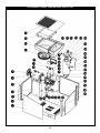
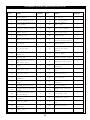
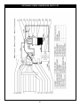
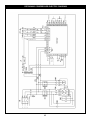
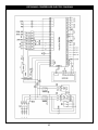
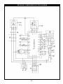
Parts List and Electric Diagrams . . . . . . . . . . . . . . . . . . . . . . . . . . . . . . . . . . . . . . . . . . . . . . . . . . . . . . . . . . . . . . . . . 36 - 44
Warranty . . . . . . . . . . . . . . . . . . . . . . . . . . . . . . . . . . . . . . . . . . . . . . . . . . . . . . . . . . . . . . . . . . . . . . . . . . . . . . . . . . . . . . . 45
Maintenance/Inspection Records . . . . . . . . . . . . . . . . . . . . . . . . . . . . . . . . . . . . . . . . . . . . . . . . . . . . . . . . . . . . . . . . 46 - 47
NOTE:
Every effort has been taken to ensure complete and accurate instructions have been included in this manual, however, possible
product updates, revisions and or changes may have occurred since this printing. BendPak Ranger reserves the right to change
specications without incurring any obligation for equipment previously or subsequently sold.
Not responsible for typographical errors.
TABLE OF CONTENTS

3
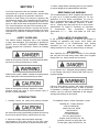
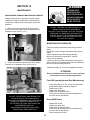
SECTION 1
Our Screw Compressor units are intended to provide
compressed air to power pneumatic tools, operate spray
equipment and supply air for pneumatic valves and
actuators. A small amount of oil carryover is present in the
compressed air stream. The compressed air has a nal oil
level of < 3ppm. Applications requiring higher levels of air
free of oil vapor should have the appropriate filter installed.
The Screw compressor units are to be mounted per the
instructions provided on a solid floor. Any other use of these
units will void the warranty and the manufacturer will not be
responsible for problems or damages resulting from such
misuse.
SAFETY GUIDELINES
This manual contains information that is very important
to know and understand. This information is provided for
SAFETY and to PREVENT EQUIPMENT PROBLEMS.
To help recognize this information, observe the following
symbols.
Watch for this symbol: It Means: Immediate hazards which
will result in severe personal injury or death.
Watch for this symbol: It Means: Hazards or unsafe practices
which could result in severe personal injury or death.
Watch for this symbol: It Means: Hazards or unsafe
practices which may result in minor personal injury or
product or property damage.
INTRODUCTION
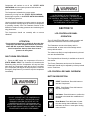
1. Carefully remove the crating and packing materials.
Be careful when cutting steel banding material as items may
become loose and fall causing personal harm or injury.
2. Check the voltage, phase and proper amperage
requirements for the motor shown on the motor plate.
Wiring should be performed by a certified electrician only.
3.
Confirm voltage before connecting power to your machine
or serious damage to the motor/electronics will result.
BREATHABLE AIR WARNING
This compressor/pump is NOT equipped and should NOT
be used “as is” to supply breathing quality air. For any
application of air for human consumption, you must fit
the air compressor/pump with suitable in-line safety and
alarm equipment. This additional equipment is neces-
sary to properly filter and purify the air to meet minimal
specifications for Grade D breathing as described
in Compressed Gas Association Commodity
Specification G 7.1 - 1966, and OSHA 29 CFR 1910.
134.
DISCLAIMER OF WARRANTIES
In the event the compressor is used for the purpose of
breathing air application and proper in-line safety and
alarm equipment is not simultaneously used, existing
warranties are void, and the company disclaims any
liability whatsoever for any loss, personal injury or damage!
UNPACKING
After unpacking the unit, inspect carefully for any damage
that may have occurred during transit. Make sure to tighten
fittings, bolts, etc., before putting unit into service.
Do not operate unit if damaged during shipping, handling
or use. Damage may result in bursting and cause injury or
property damage.
Failure to follow danger, warning, and caution instructions
may lead to serious personal injury or death to operator
or bystander or damage to property. Do not operate this
machine until you read and understand all the dangers,
warnings and cautions in this manual.
For additional copies or further information, contact:
BendPak Inc. / Ranger Products
1645 Lemonwood Dr.,
Santa Paula, CA. 93060
1-805-933-9970
www.bendpak.com
Tel: (805) 933-9970
Toll Free: (800) 253-2363
Support: (800) 253-2363 Ext. 196
Customer Service Fax: (805) 933-1128
To order parts: (800) 253-2363 Ext. 191

4
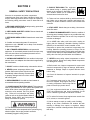
SECTION 2
GENERAL SAFETY PRECAUTIONS
Since the air compressor and other components
(material pump, spray guns, filters, lubricators, hoses, etc.)
may be under high pressure and be subject to explosions,
the following safety precautions must be observed at all
times:
1. READ AND UNDERSTAND all safety warning procedures
before installation and operation.
2. KEEP HANDS AND FEET CLEAR. Remove hands and
feet from any moving parts.
3. KEEP WORK AREA CLEAN. Cluttered work areas invite
injuries.
4. Consider work area environment. Do not expose
equipment to rain . DO NOT use in damp or wet locations.
Keep area well lighted.
5. ONLY TRAINED OPERATORS should operate this
equipment. All non-trained personnel should be kept away
from work area. Never let non-trained personnel come in
contact with, or operate machine.
6. USE MACHINE CORRECTLY. Use machine in the proper
manner. Never use adapters other than what is approved by
the manufacturer.
7. DO NOT override or disable safety valves and/or devices.
8. NEVER operate compressor without a belt
guard or Side covers in place This unit can start
automatically without warning. Personal injury
or property damage could occur from contact
with moving parts.
9. DRESS PROPERLY. Non-skid steel-toe footwear is
recommended when operating machine.
10. GUARD AGAINST ELECTRIC SHOCK. This equipment
must be grounded while in use to protect the operator from
electric shock. Never connect the green power
cord wire to a live terminal. This is for ground
only. Follow all local electrical and safety
codes as well as the United States National
Electrical Codes (NEC) and Occupational
Safety and Health Act (OSHA).
11. The motor on this machine contains high voltage.
Disconnect power at the receptacle before performing any
electrical repairs. Secure plug so that it cannot be
accidentally plugged in during service.
12. RISK OF EXPLOSION. This equipment
has internal arcing or sparking parts which
should not be exposed to flammable vapors.
This machine should not be located in a
recessed area or below floor level.
13. Tanks rust from moisture build-up, which weakens the
tank. Make sure to drain tank regularly and inspect peri-
odically for unsafe conditions such as rust formation and
corrosion.
14. STAY ALERT. Watch what you are doing. Use common
sense. Be aware.
15. CHECK FOR DAMAGED PARTS. Check for condition of
all moving parts, breakage of parts or any condition that may
affect the machines operation. Do not use if any component
is broken or damaged.
16. An ASME code safety relief valve with a setting no
higher than the Maximum Allowable Working Pressure
(MAWP) of the tank MUST remain installed on this
compressor to protect the pressurized components from
bursting. Maximum operating pressure is 150 psi. Do not
operate with pressure switch or pilot valves set higher than
150 psi. Never attempt to adjust ASME safety valve. Keep
safety valve free from paint and other accumulations.
17. NEVER remove safety related components or device
from the machine. Do not use if safety related components
are damaged or missing.
18. Before each use, inspect compressed air system and
electrical components for signs of damage, deterioration,
weakness or leakage. Repair or replace defective items
before using.
19. Check all fasteners at frequent intervals for proper
tightness.
20. Compressor parts may be hot even if
the unit is stopped. Keep fingers away from
a running compressor; fast moving and hot
parts will cause injury and/or burns.
21. If the equipment should start to vibrate abnormally,
STOP the engine/motor and check immediately for the
cause. Vibration is generally an indication of trouble.
22. To reduce fire hazard, keep engine/motor exterior free
of oil, solvent, or excessive grease.
22. Never attempt to repair or modify a tank. Welding,
drilling or any other modification will weaken the tank
resulting in damage from rupture or explosion. Always
replace worn, cracked or damaged tanks. Drain liquid from
tank daily.

5
SPRAYING PRECAUTIONS
1. Fast moving air will stir up dust and debris which may
be harmful. Release air slowly when draining moisture or
depressurizing the compressor system.
2. Do not spray flammable materials
in vicinity of open flame or near ignition
sources including the compressor unit. Do
not smoke when spraying paint, insecti-
cides, or other flammable substances.
3. Use a face mask/respirator when
spraying and spray in a well ventilated area
to prevent health and fire
hazards.
4. Do not direct paint or other sprayed material at the
compressor. Locate compressor as far away from the
spraying area as possible to minimize over spray
accumulation on the compressor.
5. When spraying or cleaning with solvents or toxic
chemicals, follow the instructions provided by the chemical
manufacturer.
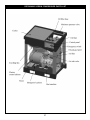
SECTION 3
GENERAL OVERVIEW
The BendPak Hush-Quiet™ RS7580H603 Rotary Screw
Air Compressor produces well over twice the CFM of
conventional, reciprocating piston compressors.
The RS7580H603 is engineered for high performance,
efciency, reliability and blessed silence to meet the
excessive demands of high-volume automotive
shops and dealerships like yours.
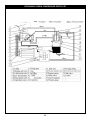
WORKING PRINCIPLES
COMPRESSION: Air is drawn through the Air Intake
Filter and Intake Control Valve then, the twin rotary screws
compress the air smoothly and efciently. At the same time,
oil is injected into the compressing cavity to cool and
lubricate the screw assembly.
OIL SEPARATION: The compressed air and oil
mixture is then run through the air and oil separation
cartridge. The majority of the oil is separated out from the
compressed air by gravity and centrifugal force. The
remaining oil mist is removed from the air oil mixture by
passing the air though the Separation Cartridge core.
The compressed air has a nal oil level of < 3ppm.
The oil is then ltered and returned to the
reciprocating screw assembly for reuse via an oil return
tube tted with a valve assembly to limit the loss of
pressure in the compressed air line.
COOLING: After the oil is separated from the
compressed air it is routed to the after cooler. The
compressed air temperature is lowered by 7 -10°C/ 4-7°F
above the ambient temperature. A minimum pressure valve
is used to guarantee that at startup there is always the
minimum pressure needed to maintain oil pressure for
operation. A check valve prevents the compressed, cooled,
air from owing backwards through the separation
element.
SYSTEM CONTROLS
The goal of the control system is the regulation of the air
intake during all phases of operation and startup. The
Control System is comprised of intake valve, work
piston, magnetic valve and pressure gauge.
STARTUP: The spring loaded intake valve requires
minimum pressure to open and generate enough
pressure to get the lubricating oil owing to the
reciprocating screws at startup.
LOAD: At load the vacuum within the compressor keeps
the intake valve open, and the system pressure
increases.
FULL LOAD: When the oil separation pressure
chamber reaches 0.4MPa the pressure valve opens to al-
low the compressed air to ow out.
NO LOAD: When the pressure of the outow line
reaches the desired rated pressure, the pressure switch
opens the magnetic valve and the system pressure drops
to the minimum required to maintain a proper ow of the
lubricating oil.
CONDENSATION: At lower operating temperatures the
amount of water that can condense into the oil is higher.
The Compressor is equipped with a thermostatic valve set
to 70° C (158*F), oil will not pass through the oil cooler until
it reaches the set temperature of 70° C /158°F.

6
The Compressor is best operated in a clean,
temperature controlled environment. If the compressor
is going to be operated with an air intake temperature
below 5°C / 41°F an anti-condensation apparatus is
required and the oil separation element should be
heated.
OVERHEATING: If the ambient temperature is above
40°C,/ 104°F or the compressor is operating in an area
near a heat source, the compressors cooling capacity
may not be adequate enough to prevent damage to the
compressor. In that case, the intake air may need to be
cooled or plumbed to and draw air from a ltered outside
air source.
If the work load is consistently below 100% of the
compressor’s rated full load, a higher ambient operating
pressure temperature may be satisfactory. The
maximum internal working temperature is 105°C / 221
°F, operating above this temperature will cause the
compressor to stop working and may cause permanent
damage.
DISCHARGE TEMPERATURE: Discharge temperature
is measured at the vent frame end of the compressor.
The Discharge temperature will vary according to
operating and environmental conditions, temperature,
load percentage, the cleanliness of the oil, cleanliness
of the intake lter and the cleanliness of the oil lter.
The normal discharge temperature is between 70°C and
90°C / 158°- 194°F When the compressor starts up from
a cold condition, the discharge temperature will quickly
rise to 85°C / 185°F, then the thermostatic valve will
open and close to regulate the discharge
temperature.
LUBRICATION: PowerCool is a powerful synthetic lubri-
cant that’s designed to help rotary screw air compressors
reach maximum performance. The PowerCool unique \
formulation has a 2-year / 8,000-hour useful lifespan
to save you money otherwise spent on disposal fees.
Other lubricants can require changing up to 8 times as
often as PowerCool. The carryover is up to 75% lower
than mineral oils and PAOs, which means less uid for
makeup and reduced contamination. All this results in
superior compressor performance, which in turn leads to
lower costs from excellent cooling and superior
efciency.
SECTION 4
INSTALLATION AND INSPECTION
BEFORE OPERATION
LOCATION REQUIREMENTS:
Disconnect, tag and lock out power source then
release all pressure from the system before attempting
to install, service, relocate or perform any maintenance.
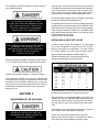
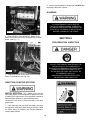
Do not lift unit by attaching any lifting device onto
the outside case. DO NOT lift or move unit without
appropriately rated forklift, pallet jack or other lift-
ing device. There are slots in the base frame of the
compressor for the forklift or pallet jack forks. (See Fig. 4.1)
Never use the wood shipping pallet for mounting the
compressor.
Install and operate unit at least 39” / 1m from any
obstructions in a clean, well ventilated area. This will
ensure an unobstructed flow of air to cool compressor
and allow adequate space for maintenance.
The surrounding air temperature should not exceed
100° F / 38° C. Do not locate the compressor air inlet
near steam, paint spray, sandblast areas or any other
source of contamination.
NOTE:
If compressor operates in a hot, moist environment,
supply compressor pump with clean, dry outside air.
Supply air should be piped in from external sources.
Fig. 4.1

7
The compressor should be located in a clean, dust free,
well ventilated location.
Ambient operating temperature should be greater than 41°
F / 5° C to allow for the minimum required oil lubrication.
Compressor should be located on a solid level surface.
The Compressor location should be well ventilated and
precautions should be taken to exhaust the warm exhaust
air outside of the compressor building and or prevent the
warm exhaust air from being drawn into the air intake or
increasing the ambient temperature of the compressor
building or room.
SECTION 5
REQUIREMENTS FOR AIR PIPING
Any tube, pipe or hose connected to the unit must be able
to withstand the temperature generated and retain the pres-
sure. All pressurized components of the air system, tube,
pipe or hose must have a pressure rating higher than or
equal to 200 psi or bursting could result and injury occur.
Connect the piping system to any accumulation tank using
the same size fitting as the discharge port.
Pipe thread lubricant must be used on all male pipe threads,
and all joints are to be made up tight, since small leaks in the
piping system are the largest single cause of high operating
costs. All piping should be sloped to an accessible drain
point and all outlets should be taken off from the top of the
main distribution air line so that
moisture cannot enter the outlet.
INSTALLING A SHUT-OFF VALVE
A shut-off valve should be installed on the discharge
port of the Compressor to control the air flow and iso-
late the components for maintenance. The valve should
be located between the tank and the piping system.
When creating a permanently installed system to
distribute compressed air, find the total length of the
system and select pipe size from the chart.
Bury underground lines below the frost line and avoid
pockets where condensation can gather and freeze.
Apply air pressure to the piping installation and make sure
all joints are free from leaks BEFORE underground lines
are covered. Before putting the compressor into service,
find and repair all leaks in the piping, fittings and connec-
tions.
The diameter of the discharge pipe should be a least the
same as that of the compressor’s output pipe.
All pipe and connectors should be able to bear the
rated pressure and be rated for compressed air delivery
and comply with all local building and safety codes.
THE AIR NEEDS TO BE FREE OF TOXIC
FUMES OR GASES, INFLAMMABLE GAS OR
EXPLOSIVE GAS. DO NOT STORE TOXIC,
VOLATILE, CORROSIVE OR FLAMMABLE
AGENTS NEAR THE COMPRESSOR.
NEVER USE PLASTIC (PVC) PIPE FOR
COMPRESSED AIR. SERIOUS INJURY OR
DEATH COULD RESULT.
THE COMPRESSOR SHOULD NOT BE LOCATED
OUTDOORS. THE AIR INTAKE OF ANY
BUILDING OR ENCLOSED STRUCTURE MUST
BE FILTERED TO HELP ELIMINATE
THE DUST IN THE AIR.

8
The conguration should meet the requirements for the ve-
locity of compressed air.
The pressure drop of the pipeline must exceed the set
pressure by 5% or more.
Use the minimum amount of bends to ensure the
smoothest airow as possible. If the pipeline run is long,
the diameter of the pipe should be increased.
Prevent any condensation from owing into any
equipment by installing the pipeline run with a minimum
slope of 1-2˚ with drain valves located at the low spots.
Slope piping so that it drains towards a drop leg or
moisture trap away from the compressor.
Consideration of future emergencies, temporary
compressor and maintenance needs of equipment should
be incorporated into the pipeline design and may include
bypass lines, shut off valves, air take off locations, strain
on the piping due to dead weight of the pipe, expansion
and contraction of the pipe, strains for internal pressure.
An air oil separator should be installed at the head of the
pipeline.
A one way valve is mounted on the exit line of the
compressor.
The compressor has integrated anti vibration devices and
does not have any support for the air pipeline. All
external piping requires approved support systems. All
piping should be connected to the compressor out line in
such a manner as to keep any condensation from running
back towards the compressor.
When an air drier is installed in the pipeline, an air tank/
reservoir is recommended as the compressed air
temperature will be lowered prior to entering the dry-
ing system and therefore increase the efcien-
cy and lower the energy use of the drying system.
A flexible hose or coupling should be installed between
the compressor and the service piping/ and or the tank;
and the tank and the service piping.
Failure to properly install the tank can lead to cracks at
the welded joints and possible bursting.
SECTION 6
FLOOR MOUNTING
The compressor should be bolted onto a flat, even,
concrete floor or on a separate concrete foundation.
If installing the optional Air Tank, Anti-vibration pads
should be used between the tank legs and the floor.
When using anti-vibration pads, do not draw bolts tight.
Allow the pads to absorb vibrations. (See Fig. 6.1)
SECTION 7
ELECTRICAL CONNECTIONS
Fig. 6.1
DO NOT PERFORM ANY MAINTENANCE OR
INSTALLATION OF ANY COMPONENTS
WITHOUT FIRST ENSURING THAT ELECTRICAL
POWER HAS BEEN DISCONNECTED AT
THE SOURCE OR PANEL AND CANNOT BE
RE-ENERGIZED UNTIL ALL
MAINTENANCE AND/OR INSTALLATION
PROCEDURES ARE COMPLETED.

9
Overheating, short circuiting and fire damage will result from
inadequate wiring. Wiring must be installed in
accordance with National Electrical Code and local codes
and standards that have been set up covering electrical
apparatus and wiring.
POWER: Standard Requirements; 230V, 3Phase, 60HZ,
Grounded.
Be certain that adequate wire sizes are used, and that:
1. Service is of adequate ampere rating.
2. The supply line has the same electrical characteristics
(voltage, cycles and phase) as the motor.
3. The line wire is the proper size and that no other
equipment is operated from the same line. The chart below
gives minimum recommended wire sizes for compressor
installations.
Recommended wire sizes may be larger than the
minimum set up by local ordinances. If so, the larger size
wire should be used to prevent excessive line voltage
drop. The additional wire cost is very small compared
with the cost of repairing or replacing a motor electrically
“starved” by the use of supply wires which are too small.
Improperly grounded electrical components are shock
hazards. Make sure all the components are properly
grounded to prevent death or serious injury.
This product must be grounded.
Grounding reduces the risk of electrical
shock by providing an escape wire for
the electric current if short circuit occurs.
This product must be installed and oper-
ated with a power cord or cable that has
a grounding wire.
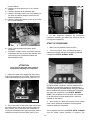
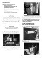
The base of the unit has holes in it for routing of the
power cord. (See Fig. 7.1)
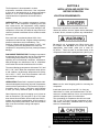
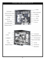
1. Remove the Access panel on the Power Control
Box Side of the Compressor. (See Fig. 7.2)
ALL WIRING AND ELECTRICAL CONNECTIONS
MUST BE PERFORMED BY A QUALIFIED
ELECTRICIAN. INSTALLATION MUST BE IN
ACCORDANCE WITH LOCAL AND
NATIONAL CODES.
Fig. 7.1
Fig. 7.2

10
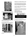
2. Route the power cable through the bottom of the
Power Control Box and to the Terminal Block as shown
below. (See Fig. 7.3 )
3. Connect the Power Source Wires to the incoming
Power Terminal Block. (See Fig. 7.4)
DIRECTION OF MOTOR ROTATION
MOTOR ROTATION: The 3 Phase power must be
connected properly to the compressor to ensure the motor
is rotating in the right direction. The compressor controller is
fitted with phase detection to prevent damage to the
compressor In the event of miss-connection of the three
phase power.
1. If the motor does not start upon first startup, then likely
the sequence of the three phase wiring is incorrect. Check
the Failure history as outlined in the Trouble Shooting to
confirm phase problem.
2. Reverse the two phases of power input. DO NOT alter
the wiring of the motor or starter.
GUARDING
SECTION 8
PRE-OPERATION INSPECTION
ALL MAINTENANCE PANELS MUST BE
INSTALLED DURING NORMAL OPERATION.
ALL MOVING PARTS MUST BE GUARDED. ALL
ELECTRICAL COVERS MUST BE INSTALLED
BEFORE TURNING ON THE POWER.
Fig. 7.3
Fig. 7.4
DO NOT PERFORM ANY MAINTENANCE OR
INSTALLATION OF ANY COMPONENTS
WITHOUT FIRST ENSURING THAT ELECTRICAL
POWER HAS BEEN DISCONNECTED AT
THE SOURCE OR PANEL AND CANNOT BE
RE-ENERGIZED UNTIL ALL
MAINTENANCE AND/OR INSTALLATION
PROCEDURES ARE COMPLETED.

11
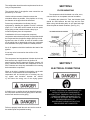
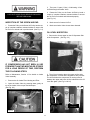
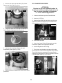
INSPECTION OF THE SCREW AIR END
1. Rotate the Pulley on the Screw Air End by hand a cou-
ple of complete rotations counterclockwise to ensure the
Air End is not locked and is pre-lubricated. (See Fig. 8.1)
IF COMPRESSOR HAS NOT BEEN IN USE
FOR MORE THAN TWO MONTHS OR STORED
FOR A LONG PERIOD OF TIME, PERFORM
THE FOLLOWING STEPS:
Refer to Maintenance, Section 12 for details on Intake
Valve Assembly.
1. Remove the Air Intake Filter Housing and Filter.
2. Open the Intake Valve by pressing down gently on
top of the Intake Valve to open and hold open.
(See Fig. 8.2)
3. Then pour .5 quart (.5 litre) of lubricating oil into
Air End through the Intake Valve.
4. Rotate the Pulley on the Screw Air End by hand a
couple of complete rotations counterclockwise to ensure
the Air End is not locked and lubricated properly.
(See Fig. 8.1)
5. Make sure all oil enters Air End.
6. Make sure Intake Valve closes when released.
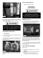
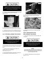
OIL LEVEL INSPECTION
1. Remove the Access panel on the Oil Separator Side
of the Compressor. (See Fig. 8.3)
2. The oil level must be above the upper red line after
the compressor is off has been stopped for thirty minutes
The oil level when the compressor is running must be
between the upper and lower red line indicated on the Oil
Level Site glass. (See Fig. 8.4 & 8.5)
Fig. 8.1
Fig. 8.2
LOCK OUT SOURCE AND RELIEVE PRESSURE
BEFORE SERVICING.
Fig. 8.3
Oil Fill Plug
Oil Level
Site Glass
Fig. 8.4

12
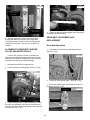
3. Fill with PowerCool Synthetic Air Compressor
Lubricant if necessary and inspect the O-Ring on the Oil
Fill Plug before tightening.
TRANSMISSION INSPECTION:
Belt Inspection.
1. Remove the Access panel on the right side Drive Belt
Side of the Compressor.
2. Check that all drive belts are in the pulley grooves.
Adjust the tension of belts through the adjusting Bolt on
motor. (See Fig. 8.6)
(See Belt maintenance on page 28 for Belt adjustment
details.)
STOP VALVE INSPECTION
Check if the stop valve is open.
SECTION 9
DAILY OPERATION
EMERGENCY STOP
1. To immediately stop the Compressor press the
Emergency Stop Button to cut off the power supply of the
controller and contactor power. (See Fig. 9.1)
2. To Reset Emergency Stop; Twist Emergency Stop
Button clockwise, The Emergency Stop Button will pop
back out. The Compressor cannot be restarted until the
failure has been cleared and the Restart Delay time (90
seconds) has expired.
3. The Compressor cannot be restarted until the failure
has been cleared and the Restart Delay time (90 seconds
default) has expired.
DAILY STARTUP PROCEDURE:
Before start up:
a) Check the operating button to see if it is in normal
condition.
b) Make sure there are no abnormal noise vibration or
oil leakage.
c) Check the instruments of pressure gauge, oil
thermometer, ammeter, indicator light, etc are in
Fig. 8.6
DO NOT OVER FILL. OVER FILLING CAN CAUSE
A HIGH LEVEL OF OIL IN THE COMPRESSED AIR.
DO NOT UNDER FILL. UNDER FILLING CAN CAUSE
OVER HEATING AND DAMAGE.
Minimum Oil Level
when stopped
and cold
Minimum Oil Level
while running
Fig. 8.5
IN THE EVENT OF ANY TROUBLE OR
OPERATION PROBLEM NOT DETECTED
AND TERMINATED BY THE CONTROL SOFTWARE.
THE COMPRESSOR CAN BE SHUT DOWN BY
PRESSING THE EMERGENCY STOP BUTTON.
Emergency Stop
Button
Fig. 9.1

13
normal condition.
d) Check the oil return pipe to see if it is in normal
condition.
e) Check the pressure of the automatic stop.
f) Check the unloading valve to see if it is deating or
not when the machine stopped. Check also the
exhaust temperature.
g) Check the voltage and electric current to see if they
are in normal condition.
h) Check, clean and replace the safety valve if
necessary.
i) Record the voltage, current, air pressure, exhaust
temperature and oil level every day and take notes
of the working time, maintenance status and
abnormalities per shift.
ATTENTION:
Don’t open oil drain ball valve until ve
minutes after stopping the compressor.
1. Open the oil drain valve slightly and drain off any
water from the bottom of the oil Tank. Drain uid until
water stops owing and only oil ows. (See Fig. 9.2 )
2. The oil level must be above the upper red line after
the compressor is shut off and has been stopped for
thirty minutes. The oil level when the compressor is
running must be between the upper and lower red line
indicated on the Oil Level Site Glass. (See Fig. 9.3 )
3. Fill with PowerCool Synthetic Air Compressor
Lubricant if necessary and inspect the O-Ring on the Oil
Fill Plug before tightening.
START UP PROCEDURE:
1. Make sure any installed valves are open.
2. Turn on the Power; The LCD Display will show a
welcoming message and then the Display will indicate
Compressor’s STATE: NORMAL STOP.
3. Press the ON Button; The compressor will begin
the Delayed Start countdown, once the delayed time is
reached the Compressor will start up automatically. If
necessary pressing the STOP Button during the delayed
Start Countdown will Stop the delayed start Countdown
and place the Compressor in the STATE: NORMAL
STOP. (The compressor will not be able to be restarted
for at least ninety seconds (default) after it has been
stopped for any reason.)
4. After starting up: Watch the pressure on the control
panel. Check operating temperature and the general
conditions inside the compressor.
The Compressor will run in the STATE: AUTO LOADING
until the preset system pressure is reached. The
Minimum Oil Level
when stopped
and cold
Minimum Oil Level
while running
Fig. 9.3
Fig. 9.2

14
Compressor will continue to run in the STATE: AUTO
UNLOADING until the system pressure falls below the
preset minimum pressure.
The Compressor maintains the preset system
pressure by moving from the STATE: AUTO LOADING,
pressuring the system, to the STATE: AUTO UNLOADING;
not building any pressure.
Use the monitoring features to monitor pressure, power and
other compressor running values to ensure the Compressor
is operating normally. See The Parameter Section of this
Manual for details on setting pressures and monitoring run-
ning parameters.
The Compressor should run smoothly with no excess
vibrations.
ATTENTION:
Do not restart compressor up within 90 Seconds after
compressor has been stopped. Release all pressure
within AIR OIL separation element before restarting.
Avoid compressor start up when there is back
pressure in the system.
SHUT DOWN PROCEDURE:
1. Press the OFF button, the compressor will move to
STATE: READY STOP. The Controller will countdown the
Remaining delay until the Compressor will stop and then
shut down the Compressor when the set time is reached.
If the compressor has begun the stop sequence, Press the
Emergency Stop Button if you need to stop the compressor
immediately.
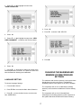
SECTION 10
LCD CONTROLLER PANEL
OPERATION
The LCD CONTROLLER panel is used to monitor and
adjust the Parameters of the Screw Compressor.
The Parameters are set at the factory and it is
recommended to leave most of the settings at their
factory default values.
The values most likely to require adjustment by the end
user are described below.
The Complete Menu Hierarchy is available at the end of
this section.
The Factory Parameters and some of the Customer
Parameters should only be adjusted by a factory trained
service Technician.
LCD CONTROLLER PANEL OVERVIEW
BUTTON DESCRIPTION
START Start Button; Press this button to
start the Compressor.
STOP Stop Button: Press this button to
stop the Compressor.
Set Button: Press this button to conrm the
input data to be saved after modication of
the data.
Down Button: Press this button to lower
the value during data modication. Press
this button to select a menu option during
menu selection.
DO NOT ASSUME THAT THE COMPRESSOR
CAN NOT STARTUP IF THE MOTOR IS NOT
RUNNING. CONFIRM THE STATE OF THE
COMPRESSOR BEFORE PERFORMING ANY
OPERATION, INSPECTION OR WORK NEAR THE
MOTOR AND ENSURE LOCK OUT AND TAG OUT
PROCEDURES HAVE BEEN PERFORMED.
IN THE EVENT OF ANY TROUBLE OR
OPERATION PROBLEM NOT TERMINATED BY
THE CONTROL SOFTWARE. THE COMPRESSOR
CAN BE SHUT DOWN BY PRESSING
THE EMERGENCY STOP BUTTON.
S

15
Up Button: Press this button to raise the value
during data manipulation. Press this button to
select a menu option during menu selection.
Right Button: This button can be used as
cursor during the data modication and as
conrm button during menu selection.
Escape Button: Press this button to return to
the menu operation or to previous page.
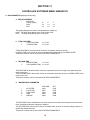
STATUS DISPLAY AND OPERATION:
1. When the unit is powered up, the Display interface
will display the welcome screen as follows:
AFTER FIVE SECONDS THE DISPLAY WILL CHANGE:
AIR T: Indicates air temp in degrees Celsius.
STATE: Indicates Current Motor State.
P: Indicates PSI
ADD0001: Indicates Network Address.
0 S: Indicates number of seconds remaining if
in a “DELAY STATE”
NEAR: Indicates Local Control (NEAR) or
Remote Control. (Far)
RUN PARAMETER
Use the RUN PARAMETER menu to view or monitor the
compressor settings while running in any state.
The settings cannot be changed or modied in this view
but can be changed from other menus.
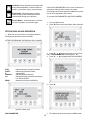
To view the RUN PARAMETER: MOTORS CURRENT:
1. From the Main screen:
2. Press ê Enter to access the Main Menu Selection.
3. Press ê or é to move the black cursor over the
menu “RUN PARAMETER” and then press è .
4. Press ê or é to highlight MOTORS CURRENT.
5. Press è .
5. The display will show the amount of AMPS drawn
S

16
per leg for the HOST (Main Motor) and the FAN (Cooling
Fan).
6. Press the RETURN button “RT” and return to the
upper menu or the main screen.
NOTE:
The display will automatically return to the main
screen after several seconds of inactivity.
To view the other RUN PARAMETERS such as the
TOTAL RUN TIME, THIS RUN TIME, MAINTENANCE
PARAMETER, HISTORY FAULT, PRODUCTION DATE
and THIS FAULT, return to the upper level menus and
use the same method used to view MOTORS CURRENT
parameters to view the other settings.
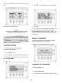
CALENDAR SETTING
To adjust the Date; (No Password is
required to modify the Date).
1. From the Main screen:
2. Press ê Enter to access the Main Menu Selection.
3. Press ê to move the black cursor over the menu
item “FACTORY PARA.”
4. Press è .
5. Press ê or é to highlight and choose “DATA”.
6. Press è .
7. The number will blink indicating it is modiable. Use
the ê or é button to change the values of the
selected parameter (month, day, year). Press the “S”
button to conrm and save the data after nishing the
modication.
DEFAULT “PASSWORD”
Some of the settings require a pin code, the factory
default password you can use is 1688.
Use the ê or é buttons to enter the numbers.
CHANGING THE “PASSWORD”
To reset the Password.
1. From the Main screen:
2. Press ê Enter to access the Main Menu Selection.

17
3. Press ê or é to highlight the menu item
“USER PARAMETER”.
4. Press è .
5. Press ê or é to highlight the menu item “NEW
USER PASSWORD” . Located on the Third row down.
6. Press è .
7. Use the ê or é button to change the values of the
selected parameter. Press the “S” button to conrm and
save the data after nishing the modication.
LANGUAGE SETTING
To choose Language Settings:
1. From the Main Screen:
2. Press ê Enter to access the Main Menu Selection.
3. Press ê to move the black cursor over the menu
item “USER PARA.”
4. Press è .
5. Press ê to choose “LAN. SEL: EN”
6. Press è .
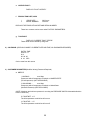
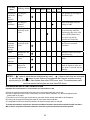
CHANGING THE MAXIMUM AND
MINIMUM SYSTEM PRESSURE
SETTINGS
The maximum and minimum pressure in the system have
already been pre-set by the factory. The Maximum
allowable pressure in the system is 150 PSI (1.034Mpa).
The compressor will run in a Loaded State (building
pressure) until it reaches the Maximum Pressure Setting
value.
The compressor will run in an Unloaded State
(Running but not building pressure) until the pressure in
the system falls below the Minimum Pressure Setting.

18
The Range Value represents the amount of pressure
below the Maximum Pressure Setting that will trigger the
Compressor to change from Unloaded State (not building
pressure or Normal Off State to Loaded State Building
Pressure).
Example:
Max Pressure is set at: 150 PSI / 1.034 Mpa
Range Value set at: 25 PSI / .172 Mpa.
The Minimum Pressure is 125 PSI / .862 Mpa
(150 Max) - (Range 25 PSI) = Min 125 PSI
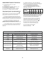
Use the Chart below to convert PSI to Mpa.
DO NOT ASSUME THE COMPRESSOR
CAN NOT STARTUP IF THE MOTOR
IS NOT RUNNING. CONFIRM THE STATE OF
THE COMPRESSOR BEFORE PERFORMING ANY
OPERATION, INSPECTION OR WORK NEAR THE
MOTOR AND ENSURE LOCK OUT AND TAG OUT
PROCEDURES HAVE BEEN PERFORMED.
DO NOT PERFORM ANY MAINTENANCE OR
INSTALLATION OF ANY COMPONENTS WITH OUT
FIRST ENSURING THAT ELECTRICAL POWER HAS
BEEN DISCONNECTED AT THE SOURCE OR PANEL
AND CANNOT BE RE-ENERGIZED UNTIL ALL
MAINTENANCE AND/OR INSTALLATION
PROCEDURES ARE COMPLETED.
PSI Mpa Bar kg/cm2
1 0.007 0.07 0.07
25 0.172 1.72 1.76
50 0.345 3.45 3.52
75 0.517 5.17 5.27
100 0.689 6.89 7.03
110 0.758 7.58 7.73
110 0.758 7.58 7.73
120 0.827 8.27 8.44
130 0.896 8.96 9.14
140 0.965 9.65 9.84
145 1.000 10.00 10.19
150 1.034 10.34 10.55
160 1.103 11.03 11.25
To Convert Psi to Mpa
Multiply: Psi x .006894757 = Mpa
To Convert Psi to Kg/cm2
Multiply: Psi x .070307 = Kg/cm2
To Convert Psi to Bar
Multiply: Psi x .06894757 = Bar

19
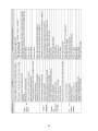
SECTION 11
CONTROLLER SOFTWARE MENU HIERARCHY
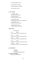
1) RUN PARAMETER (Displays Values Only)
a. MOTORS CURRENT
i. AMPS/LEG
Current (Amps) R S T
HOST x.x x.x x.x
FAN x.x x.x x.x
This setting displays the number of amps drawn per supply leg.
HOST: The amps being drawn by the main electric motor.
FAN: The amps being drawn by the cooling Fan.
b. TOTAL RUN TIME
i. TOTAL RUN TIME: x H xx M
ii. LOADING TIME: x H xx M
TOTAL RUN TIME is the total amount of time the compressor has been running.
LOADING TIME is the amount of time the compressor has been running in LOADED STATE.
These hour counters can be reset under FACTORY PARAMETERS.
c. THIS RUN TIME
i. THIS RUN TIME: x H xx M
ii. THIS LOADING TIME: x H xx M
THIS RUN TIME is the total amount of time the compressor has been running in any state during the
most recent cycle
THIS LOADING TIME is the amount of time the compressor has been running in LOADED STATE in the
most recent Cycle.
These hour counters can be reset under FACTORY PARAMETERS.
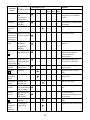
d. MAINTENANCE PARAMETER
RUN TIME SET
i. OIL FILTER 0000 0000
ii. O-G FILTER 0000 0000
iii. GAS FILTER 0000 0000
iv. LUBE 0000 0000
v. GREASE 0000 0000
The RUN TIME for each maintenance item is the amount of time since the maintenance item has been
reset, and ideally performed, changed or replaced.
The SET TIME is the amount of time set for a reminder alarm to go off to remind to change, perform or
replace the maintenance item.
These hour counters can be reset under FACTORY PARAMETERS.

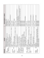
20
e. HISTORY FAULT –
DISPLAYS “FAULT HISTORY”
f. PRODUCTION DATE, NUM
i. PROD DATE: 2009:xx:xx
ii. SERIAL NUMBER: xxxxxxxx
DISPLAYS THE PRODUCTION DATE AND SERIAL NUMBER.
These hour counters can be reset under FACTORY PARAMETERS.
g. THIS FAULT-
DISPLAYS “CURRENT FAULT STATUS”
These faults can be cleared by xing fault.
2) CALENDAR- (DISPLAYS /MODIFY CURRENT DATE AND TIME, NO PASSWORD REQUIRED)
DATE & TIME
2009-11-17
W-2
00: 00: 00
H M SEC
Can be reset from this screen
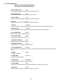
3) CUSTOMER PARAMETER (Modies Values)( Password Required)
a. SET P.T.
i. LOADING – xx.xx Mpa
Pressure at which Compressor will switch to LOADED STATE
(To build pressure). (NOT APPLICABLE)
ii. UNLOADING – xx.xx Mpa
Pressure at which Compressor will switch to Unload State.
(Not Build Pressure) (NOT APPLICABLE)
(NOTE: Maximum and minimum pressure is set using the PRESSURE SWITCH Mounted behind the
Power Control Box.)
iii. FAN START- x °C
The Oil temperature at which fan will turn on.
iv. FAN STOP - x °C
The Oil temperature at which fan will turn off.
La pagina si sta caricando...
La pagina si sta caricando...
La pagina si sta caricando...
La pagina si sta caricando...
La pagina si sta caricando...
La pagina si sta caricando...
La pagina si sta caricando...
La pagina si sta caricando...
La pagina si sta caricando...
La pagina si sta caricando...
La pagina si sta caricando...
La pagina si sta caricando...
La pagina si sta caricando...
La pagina si sta caricando...
La pagina si sta caricando...
La pagina si sta caricando...
La pagina si sta caricando...
La pagina si sta caricando...
La pagina si sta caricando...
La pagina si sta caricando...
La pagina si sta caricando...
La pagina si sta caricando...
La pagina si sta caricando...
La pagina si sta caricando...
La pagina si sta caricando...
La pagina si sta caricando...
La pagina si sta caricando...
La pagina si sta caricando...
-
 1
1
-
 2
2
-
 3
3
-
 4
4
-
 5
5
-
 6
6
-
 7
7
-
 8
8
-
 9
9
-
 10
10
-
 11
11
-
 12
12
-
 13
13
-
 14
14
-
 15
15
-
 16
16
-
 17
17
-
 18
18
-
 19
19
-
 20
20
-
 21
21
-
 22
22
-
 23
23
-
 24
24
-
 25
25
-
 26
26
-
 27
27
-
 28
28
-
 29
29
-
 30
30
-
 31
31
-
 32
32
-
 33
33
-
 34
34
-
 35
35
-
 36
36
-
 37
37
-
 38
38
-
 39
39
-
 40
40
-
 41
41
-
 42
42
-
 43
43
-
 44
44
-
 45
45
-
 46
46
-
 47
47
-
 48
48


BendPak RS7580H603 Manuale del proprietario
- Tipo
- Manuale del proprietario
- Questo manuale è adatto anche per
in altre lingue
- English: BendPak RS7580H603 Owner's manual
Altri documenti
-
DeWalt DPC10RC Manuale utente
-
-
Senco PC1010N Operating Instructions Manual
-
Hitachi EC1433H Manuale del proprietario
-
BorMann BAT5015 Manuale utente
-
BENDIX TU-FLO 1000 Manuale utente
-
-
Trane Jupiter JUAV Series Installation Operation & Maintenance
-
Ingersoll-Rand Sierra SL 90 Operation and Maintenance Manual
-
Miller AIR PAK Manuale del proprietario