
EN
English - Instruction manual
IT
Italiano - Manuale di istruzioni
FR
Français - Manuel d’instructions
DE
Deutsch - Bedienungsanleitung
RU
Русский - Руководство по эксплуатации
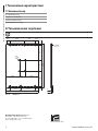
ITALIANO
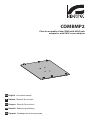
COMBMP2
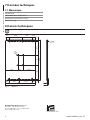
Plate for assembly of the COMB with UEAP pole
adaptor or with UEAC corner adaptor

Instruction manual - English - EN
1MNVKCOMBMP_2222_EN
ENGLISH
COMBMP2
Plate for assembly of the COMB with UEAP pole adaptor or with UEAC
corner adaptor
1 About this manual
Read all the documentation supplied carefully
before installing and using this product. Keep the
manual in a convenient place for future reference.
1.1 Typographical conventions
CAUTION!
Medium level hazard.
This operation is very important for the
system to function properly. Please read
the procedure described very carefully
and carry it out as instructed.
INFO
Description of system specifications.
We recommend reading this part carefully
in order to understand the subsequent
stages.
2 Notes on copyright and
information on trademarks
The mentioned names of products or companies are
trademarks or registered trademarks.
3 Safety rules
CAUTION! Device installation and
maintaining must be performed by
specialist technical staff only.
• Before starting any operation, make sure the
power supply is disconnected.
• The manufacturer declines all responsibility
for any damage caused by an improper use
of the appliances mentioned in this manual.
Furthermore, the manufacturer reserves the right
to modify its contents without any prior notice.
The documentation contained in this manual has
been collected and verified with great care. The
manufacturer, however, cannot take any liability
for its use. The same thing can be said for any
person or company involved in the creation and
production of this manual.
• Use only original spare parts. Non-original spare
parts could cause fire, electrical discharge or other
hazards.
4 Identification
4.1 Product description and type
designation
Plate for assembly of the COMB with UEAP pole
adaptor or with UEAC corner adaptor.
5 Preparing the product for
use
Any change that is not expressly approved
by the manufacturer will invalidate the
warranty.
5.1 Unpacking
When the product is delivered, make sure that the
package is intact and that there are no signs that it
has been dropped or scratched.
If there are obvious signs of damage, contact the
supplier immediately.
When returning a faulty product we recommend
using the original packaging for shipping.
Keep the packaging in case you need to send the
product for repairs.

EN - English - Instruction manual
2 MNVKCOMBMP_2222_EN
5.2 Safely disposing of packaging
material
The packaging material can all be recycled. The
installer technician will be responsible for separating
the material for disposal, and in any case for
compliance with the legislation in force where the
device is to be used.
5.3 Contents
Check the contents to make sure they correspond
with the list of materials as below:
• Fixing plate
• Bolts and screws
• Instruction manual
5.4 Preparatory work before
installation
Choose an installation surface that is
strong enough to sustain the weight of
the device, also bearing in mind particular
environmental aspects, such as exposure
to strong winds.
It should be installed so that no one can be
hit by moving parts. It should be installed
so that moving parts cannot hit other
objects and create hazardous situations.
Make sure the product is to be secured to
building before operation.
For technical services, consult only and
exclusively authorized technicians.
Since the user is responsible for choosing
the surface to which the unit is to be
anchored, we do not supply the fixing
devices for attaching the unit firmly to
the particular surface. The installer is
responsible for choosing fixing devices
suitable for the specific purpose on hand.
6 Installation
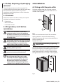
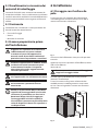
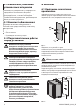
6.1 Fixing with the pole collar
To fix the support plate (01) using the 4 grower
washers in stainless steel and the 4 M8 screws in
stainless steel supplied.
01
02
Fig. 1
Make sure the thread are free of dirt and debris.
Apply a generous amount of thread locking
compound (Loctite 270) into the threaded holes in
the base of the device.
Tighten the screws.
Pay attention to the fixing. Tightening
torque: 18Nm.
The thread compound must cure for one hour, allow
for this period prior to completing the installation.
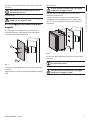
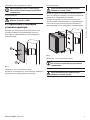
Fix the box on the plate using the 6 flat washers,
the 6 grower washers in stainless steel and the 6
hexagonal head screws in stainless steel supplied.
Fig. 2

Instruction manual - English - EN
3MNVKCOMBMP_2222_EN
Make sure the thread are free of dirt and debris.
Do not apply threadlocker to secure the
box to the plate.
Tighten the screws.
Pay attention to the fixing. Tightening
torque: 2.5Nm.
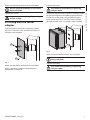
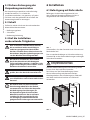
6.2 Fixing with the corner
adaptor
To fix the support plate (01) using the 4 grower
washers in stainless steel and the 4 M8 screws in
stainless steel supplied.
01
02
Fig. 3
Make sure the thread are free of dirt and debris.
Apply a generous amount of thread locking
compound (Loctite 270).
Tighten the screws.
Pay attention to the fixing. Tightening
torque: 18Nm.
The thread compound must cure for one hour, allow
for this period prior to completing the installation.
Fix the box on the plate using the 6 flat washers,
the 6 grower washers in stainless steel and the 6
hexagonal head screws in stainless steel supplied.
Fig. 4
Make sure the thread are free of dirt and debris.
Do not apply threadlocker to secure the
box to the plate.
Tighten the screws.
Pay attention to the fixing. Tightening
torque: 2.5Nm.

EN - English - Instruction manual
4 MNVKCOMBMP_2222_EN
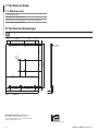
7 Technical data
7.1 Mechanical
In stainless steel
Suitable for: UEAP, UEAC
Dimensions: 358x247.6x11.7mm (14x9.7x0.4in)
Unit weight: 2.1kg (4.6lb)
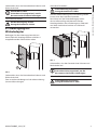
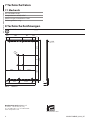
8 Technical drawings
The indicated measurements are expressed in millimetres.
103.8
28.6 28.680.3
247.6
110.2
103.840
10.7 10.7125.8 125.885
358
N°4 Ø9
3
11.7
N°6 M6
28.6 110.2 28.680.3
Fig. 5 COMBMP2.
Headquarters Italy Videotec s.r.l.
Via Friuli, 6 - I-36015 Schio (VI) - Italy
Tel. +39 0445 697411 - Fax +39 0445 697414
Email: [email protected]
www.videotec.com

Manuale di istruzioni - Italiano - IT
1MNVKCOMBMP_2222_IT
ITALIANO
COMBMP2
Piastra per il montaggio di COMB con il collare a palo UEAP o con
l'adattatore angolare UEAC
1 Informazioni sul presente
manuale
Prima di installare e utilizzare questo prodotto
leggere attentamente tutta la documentazione
fornita. Tenere il manuale a portata di mano per
consultazioni successive.
1.1 Convenzioni tipografiche
ATTENZIONE!
Pericolosità media.
L'operazione è molto importante per
il corretto funzionamento del sistema.
Si prega di leggere attentamente la
procedura indicata e di eseguirla secondo
le modalità previste.
INFO
Descrizione delle caratteristiche del
sistema.
Si consiglia di leggere attentamente per
comprendere le fasi successive.
2 Note sul copyright e
informazioni sui marchi
commerciali
I nomi di prodotto o di aziende citati sono marchi
commerciali o marchi commerciali registrati
appartenenti alle rispettive società.
3 Norme di sicurezza
ATTENZIONE! L'installazione e la
manutenzione del dispositivo devono
essere eseguite solo da personale tecnico
specializzato.
• Prima di eseguire qualsiasi operazione assicurarsi
di togliere tensione al prodotto.
• Il produttore declina ogni responsabilità per
eventuali danni derivanti da un uso improprio
delle apparecchiature menzionate in questo
manuale. Si riserva inoltre il diritto di modificarne
il contenuto senza preavviso. Ogni cura è
stata posta nella raccolta e nella verifica della
documentazione contenuta in questo manuale.
Il produttore, tuttavia, non può assumersi alcuna
responsabilità derivante dall'utilizzo della stessa.
Lo stesso dicasi per ogni persona o società
coinvolta nella creazione e nella produzione di
questo manuale.
• Utilizzare solo parti di ricambio originali. Pezzi
di ricambio non originali potrebbero causare
incendi, scariche elettriche o altri pericoli.
4 Identificazione
4.1 Descrizione e designazione
del prodotto
Piastra per il montaggio di COMB con il collare a palo
UEAP o con l'adattatore angolare UEAC.
5 Preparazione del prodotto
per l'utilizzo
Qualsiasi intervento non espressamente
approvato dal costruttore fa decadere la
garanzia.
5.1 Disimballaggio
Alla consegna del prodotto verificare che l'imballo
sia integro e non presenti segni evidenti di cadute o
abrasioni.
In caso di danni evidenti all'imballo contattare
immediatamente il fornitore.
In caso di restituzione del prodotto malfunzionante
è consigliato l'utilizzo dell'imballo originale per il
trasporto.
Conservare l'imballo qualora fosse necessario inviare
il prodotto in riparazione.

IT - Italiano - Manuale di istruzioni
2 MNVKCOMBMP_2222_IT
5.2 Smaltimento in sicurezza dei
materiali di imballaggio
I materiali d'imballo sono costituiti interamente da
materiale riciclabile. Sarà cura del tecnico installatore
smaltirli secondo le modalità di raccolta differenziata
o comunque secondo le norme vigenti nel Paese di
utilizzo.
5.3 Contenuto
Controllare che il contenuto sia corrispondente alla
lista del materiale sotto elencato:
• Piastra di fissaggio
• Viteria
• Manuale di istruzioni
5.4 Lavoro preparatorio prima
dell’installazione
Scegliere una superficie di installazione
sufficientemente resistente e adatta
a sostenere il peso dell’apparecchio,
tenendo conto di condizioni ambientali
particolari come l’esposizione a venti forti.
Installare l’apparecchio in modo da evitare
incidenti causati dal contatto con parti
in movimento, facendo sì che queste
non urtino contro altri oggetti creando
situazioni pericolose.
Prima di fornire alimentazione assicurarsi
che l’apparecchio sia saldamente ancorato.
Per l’assistenza tecnica rivolgersi
esclusivamente a personale tecnico
autorizzato.
Poiché la responsabilità della scelta della
superficie di ancoraggio dell’unità ricade
sull’utente, il produttore non fornisce in
dotazione i dispositivi di fissaggio per
l’ancoraggio dell’unità alla superficie.
L’installatore è pertanto responsabile della
scelta di dispositivi idonei alla superficie a
sua disposizione.
6 Installazione
6.1 Fissaggio con il collare da
palo
Fissare la piastra di supporto (01) utilizzando le
4 rondelle grower in acciaio inox e le 4 viti M8 in
acciaio inox fornite in dotazione.
01
02
Fig. 1
Assicurarsi che le filettature siano prive di sporcizia
e residui.
Applicare una buona quantità di frenafiletti (Loctite
270) sui fori filettati.
Serrare le viti.
Prestare attenzione durante il fissaggio.
Coppia di serraggio: 18Nm.
Lasciare agire il frenafiletti per un’ora prima di
ultimare l’installazione.
Fissare la cassetta sulla piastra utilizzando le 6
rondelle piane, 6 rondelle grower in acciaio inox
e 6 viti a testa esagonale in acciaio inox fornite in
dotazione.
Fig. 2

Manuale di istruzioni - Italiano - IT
3MNVKCOMBMP_2222_IT
Assicurarsi che le filettature siano prive di sporcizia
e residui.
Non applicare frenafiletti per fissare la
cassetta alla piastra.
Serrare le viti.
Prestare attenzione durante il fissaggio.
Coppia di serraggio: 2.5Nm.
6.2 Fissaggio con adattatore ad
angolo
Fissare la piastra di supporto (01) utilizzando le
4 rondelle grower in acciaio inox e le 4 viti M8 in
acciaio inox fornite in dotazione.
01
02
Fig. 3
Assicurarsi che le filettature siano prive di sporcizia
e residui.
Applicare una buona quantità di frenafiletti (Loctite
270).
Serrare le viti.
Prestare attenzione durante il fissaggio.
Coppia di serraggio: 18Nm.
Lasciare agire il frenafiletti per un’ora prima di
ultimare l’installazione.
Fissare la cassetta sulla piastra utilizzando le 6
rondelle piane, 6 rondelle grower in acciaio inox
e 6 viti a testa esagonale in acciaio inox fornite in
dotazione.
Fig. 4
Assicurarsi che le filettature siano prive di sporcizia
e residui.
Non applicare frenafiletti per fissare la
cassetta alla piastra.
Serrare le viti.
Prestare attenzione durante il fissaggio.
Coppia di serraggio: 2.5Nm.

IT - Italiano - Manuale di istruzioni
4 MNVKCOMBMP_2222_IT
7 Dati tecnici
7.1 Meccanica
In acciaio inox
Accoppiabile con: UEAP, UEAC
Dimensioni: 358x247.6x11.7mm
Peso unitario: 2.1kg
8 Disegni tecnici
Le misure indicate sono espresse in millimetri.
103.8
28.6 28.680.3
247.6
110.2
103.840
10.7 10.7125.8 125.885
358
N°4 Ø9
3
11.7
N°6 M6
28.6 110.2 28.680.3
Fig. 5 COMBMP2.
Headquarters Italy Videotec s.r.l.
Via Friuli, 6 - I-36015 Schio (VI) - Italy
Tel. +39 0445 697411 - Fax +39 0445 697414
Email: [email protected]
www.videotec.com

Manuel d’instructions - Français - FR
1MNVKCOMBMP_2222_FR
FRANÇAIS
COMBMP2
Plaque pour le montage de COMB avec adaptateur pour poteau UEAP ou
avec adaptateur d’angle UEAC
1 À propos de ce mode
d’emploi
Avant d'installer et d'utiliser ce produit, lire
attentivement toute la documentation fournie.
Garder le manuel à portée de main pour des
consultations successives.
1.1 Conventions typographiques
ATTENTION!
Risque moyen.
Opération extrêmement importante
en vue d’un fonctionnement correct
du système. Lire avec attention les
opérations indiquées et s’y conformer
rigoureusement.
REMARQUE
Description des caractéristiques du
système.
Il est conseillé de procéder à une
lecture attentive pour une meilleure
compréhension des phases suivantes.
2 Notes sur le copyright
et informations sur les
marques de commerce
Les noms de produit ou de sociétés cités sont
des marques de commerce ou des marques de
commerce enregistrées.
3 Normes de securité
ATTENTION! L’installation et l’entretien
du dispositif doivent être effectués
exclusivement par un personnel technique
qualifié.
• Sectionner l'alimentation avant de procéder à
toute opération.
• Le fabricant décline toute responsabilité pour
les dommages éventuels dus à une utilisation
non appropriée des appareils mentionnés
dans ce manuel. On réserve en outre le droit
d’en modifier le contenu sans préavis. La
documentation contenue dans ce manuel a été
rassemblée et vérifiée avec le plus grand soin. Le
fabricant, cependant, ne peut assumer aucune
responsabilité dérivant de l’emploi de celle là.
La même chose vaut pour chaque personne
ou société impliquées dans la création et la
production de ce manuel.
• Utiliser uniquement des pièces de rechange
d’origine. Les pièces non d’origine peuvent être
source d’incendies, de choc électrique ou autres.
4 Identification
4.1 Description et désignation du
produit
Plaque pour le montage de COMB avec adaptateur
pour poteau UEAP ou avec adaptateur d’angle UEAC.
5 Préparation du produit en
vue de l’utilisation
Toute modification non approuvée
expressément par le fabricant entraînera
l’annulation de la garantie.
5.1 Déballage
Lors de la livraison du produit, vérifier que
l’emballage est en bon état et l’absence de tout
signe évident de chute ou d’abrasion.
En cas de dommages évidents, contacter
immédiatement le fournisseur.
En cas de retour du produit défectueux, il est
conseillé d'utiliser l'emballage original pour le
transport.
Conserver l’emballage en cas de nécessité
d’expédition du produit pour réparation.

FR - Français - Manuel d’instructions
2 MNVKCOMBMP_2222_FR
5.2 Élimination sans danger des
matériaux d’emballage
Le matériel d’emballage est entièrement composé
de matériaux recyclables. Le technicien chargé de
l’installation est tenu de l’éliminer conformément
aux dispositions en matière de collecte sélective
et selon les normes en vigueur dans le pays
d’utilisation.
5.3 Contenu
Contrôler que le contenu correspond à la liste
matériel indiquée ci-dessous:
• Plaque de fixation
• Vis
• Manuel d'instructions
5.4 Opérations à effectuer avant
l’installation
Choisir une surface d'installation
suffisamment résistante et adaptée pour
soutenir le poids de l'appareil, en tenant
compte des conditions particulières du
milieu, comme l'exposition à des vents
forts.
Installer l'appareil de façon à éviter les
accidents causés par le contact avec des
parties en mouvement, en faisant en
sorte que ces parties ne se heurtent pas
à d'autres objets, créant des situations
dangereuses.
Avant d'alimenter l'appareil, s'assurer qu'il
est solidement fixé.
Pour l'assistance techniques, s'adresser
exclusivement à du personnel technique
agréé.
Etant donné que l'utilisateur est
responsable du choix de la surface de
fixation, le fabricant ne fournit pas dans
la livraison les dispositifs de fixation de
l'unité à la surface. L'installateur est donc
responsable de choisir des dispositifs
adaptés à la surface à disposition.
6 Installation
6.1 Fixation avec le collier pour
poteau
Fixer la plaque de support (01) à l'aide de 4 rondelles
grower en acier inox et 4 vis M8 en acier inox
fournies.
01
02
Fig. 1
S'assurer qu'il n'y ait pas de saleté ou de résidus dans
les taraudages.
Appliquer une bonne quantité de colle frein filet
(Loctite 270) sur les trous taraudés.
Serrer les vis.
Faire attention pendant la fixation. Couple
de serrage: 18Nm.
Laisser agir la colle frein filet pendant une heure
avant de terminer l'installation.
Fixer le boîtier sur la plaque à l'aide des 6 rondelle
plates, 6 rondelles grower en acier inox et 6 vis à tête
hexagonale en acier inox fournies.
Fig. 2

Manuel d’instructions - Français - FR
3MNVKCOMBMP_2222_FR
S'assurer qu'il n'y ait pas de saleté ou de résidus dans
les taraudages.
Ne pas appliquer de frein filet pour fixer la
boîte à la plaque.
Serrer les vis.
Faire attention pendant la fixation. Couple
de serrage: 2.5Nm.
6.2 Fixation avec adaptateur
coudé
Fixer la plaque de support (01) à l'aide de 4 rondelles
grower en acier inox et 4 vis M8 en acier inox
fournies.
01
02
Fig. 3
S'assurer qu'il n'y ait pas de saleté ou de résidus dans
les taraudages.
Appliquer une bonne quantité de colle frein filet
(Loctite 270).
Serrer les vis.
Faire attention pendant la fixation. Couple
de serrage: 18Nm.
Laisser agir la colle frein filet pendant une heure
avant de terminer l'installation.
Fixer le boîtier sur la plaque à l'aide des 6 rondelle
plates, 6 rondelles grower en acier inox et 6 vis à tête
hexagonale en acier inox fournies.
Fig. 4
S'assurer qu'il n'y ait pas de saleté ou de résidus dans
les taraudages.
Ne pas appliquer de frein filet pour fixer la
boîte à la plaque.
Serrer les vis.
Faire attention pendant la fixation. Couple
de serrage: 2.5Nm.

FR - Français - Manuel d’instructions
4 MNVKCOMBMP_2222_FR
7 Données techniques
7.1 Mécanique
En acier inox
Compatible avec: UEAP, UEAC
Dimensions: 358x247.6x11.7mm
Poids net: 2.1kg
8 Dessins techniques
Les tailles indiquées sont en millimètres.
103.8
28.6 28.680.3
247.6
110.2
103.840
10.7 10.7125.8 125.885
358
N°4 Ø9
3
11.7
N°6 M6
28.6 110.2 28.680.3
Fig. 5 COMBMP2.
Headquarters Italy Videotec s.r.l.
Via Friuli, 6 - I-36015 Schio (VI) - Italy
Tel. +39 0445 697411 - Fax +39 0445 697414
Email: [email protected]
www.videotec.com

Bedienungsanleitung - Deutsch - DE
1MNVKCOMBMP_2222_DE
DEUTSCH
COMBMP2
Platte für die Montage von COMB mit Mastmontageadapter UEAP oder mit
Winkeladapter UEAC
1 Allgemeines
Vor der Installation und Anwendung dieses Produkts
ist die gesamte mitgelieferte Dokumentation
aufmerksam zu lesen. Zum späteren Nachschlagen
das Handbuch in Reichweite aufbewahren.
1.1 Schreibweisen
ACHTUNG!
Mittlere Gefährdung.
Der genannte Vorgang hat große
Bedeutung für den einwandfreien Betrieb
des Systems. Es wird gebeten, sich die
Verfahrensweise durchzulesen und zu
befolgen.
ANMERKUNG
Beschreibung der Systemmerkmale.
Eine sorgfältige Lektüre wird empfohlen,
um das Verständnis der folgenden Phasen
zu gewährleisten.
2 Anmerkungen
zum Copyright und
Informationen zu den
Handelsmarken
Die angeführten Produkt- oder Firmennamen sind
Handelsmarken oder eingetragene Handelsmarken.
3 Sicherheitsnormen
ACHTUNG! Die Installation und Wartung
der Vorrichtung ist technischen Fachleuten
vorbehalten.
• Unterbrechen Sie die Stromversorgung, bevor die
beschriebenen Arbeiten durchgeführt werden.
• Der Hersteller lehnt jede Haftung für eventuelle
Schäden ab, die aufgrund unsachgemäßer
Anwendung der in diesem Handbuch erwähnten
Geräte entstanden ist. Ferner behält er sich
das Recht vor, den Inhalt ohne Vorkündigung
abzuändern. Die Dokumentation in diesem
Handbuch wurde sorgfältig ausgeführt und
überprüft. Der Hersteller kann dennoch keine
Haftung für die Verwendung übernehmen.
Dasselbe gilt für jede Person oder Gesellschaft,
die bei der Schaffung oder Produktion von diesem
Handbuch miteinbezogen ist.
• Es dürfen nur Original-Ersatzteile verwendet
werden. Nicht originale Ersatzteile können zu
Bränden, elektrischen Entladungen oder anderen
Gefahren führen.
4 Identifizierung
4.1 Beschreibung und
Bezeichnung des Produktes
Platte für die Montage von COMB mit
Mastmontageadapter UEAP oder mit Winkeladapter
UEAC.
5 Vorbereitung des
Produktes auf den Gebrauch
Jede vom Hersteller nicht ausdrücklich
genehmigte Veränderung führt zum
Verfall der Gewährleistungsrechte.
5.1 Entfernen der Verpackung
Bei der Lieferung des Produktes ist zu prüfen, ob die
Verpackung intakt ist oder offensichtliche Anzeichen von
Stürzen oder Abrieb aufweist.
Bei offensichtlichen Schadensspuren an der Verpackung
muss umgehend der Lieferant verständigt werden.
Im Falle der Rückgabe des nicht korrekt funktionierenden
Produktes empfiehlt sich die Verwendung der
Originalverpackung für den Transport.
Bewahren Sie die Verpackung auf für den Fall, dass das
Produkt zur Reparatur eingesendet werden
muss.

DE - Deutsch - Bedienungsanleitung
2 MNVKCOMBMP_2222_DE
5.2 Sichere Entsorgung der
Verpackungsmaterialien
Die Verpackungsmaterialien sind vollständig
wiederverwertbar. Es ist Sache des
Installationstechnikers, sie getrennt, auf jeden
Fall aber nach den geltenden Vorschriften des
Anwendungslandes zu entsorgen.
5.3 Inhalt
Prüfen Sie, ob der Inhalt mit der nachstehenden
Materialliste übereinstimmt:
• Befestigungsplatte
• Schrauben
• Bedienungslanleitung
5.4 Auf die Installation
vorbereitende Tätigkeiten
Eine Installationsoberfläche auswählen,
die ausreichend widerstandsfähig ist
und dazu geeignet, dem Gewicht des
Gerätes standzuhalten; dabei müssen die
besonderen Umgebungsbedingungen wie
starker Wind berücksichtigt werden.
Das Gerät so installieren, dass Unfälle
durch den Kontakt mit den bewegten
Teilen verhindert werden: sie dürfen nicht
gegen andere Gegenstände stoßen und so
Gefahrensituationen hervorrufen.
Vor dem Einschalten der Stromversorgung
prüfen, dass das Gerät fest verankert ist.
Für Kundendiensteingriffe wenden Sie sich
ausschließlich an autorisiertes technisches
Personal.
Da der Benutzer für die Auswahl der
Verankerungsoberfläche der Einheit
verantwortlich ist, liefert der Hersteller
die Befestigungsvorrichtungen für
die Verankerung der Einheit auf der
Oberfläche nicht mit. Der Installateur
ist daher für die Auswahl der für die
zur Verfügung stehende Oberfläche
geeigneten Vorrichtungen verantwortlich.
6 Installation
6.1 Befestigung mit Rohrschelle
Befestigen Sie die Halterungsplatte (01) mit
den 4 Edelstahl-Unterlegscheiben und den 4
mitgelieferten M8-Edelstahlschrauben.
01
02
Abb. 1
Sicherstellen, dass die Gewinde ohne Schmutz und
Rückstände sind.
Eine ausreichende Menge an Schraubensicherung
(Loctite 270) an den Gewindebohrungen anbringen.
Schrauben festziehen.
Auf die Befestigung achten.
Anzugsdrehmoment: 18Nm.
Die Schraubensicherung eine Stunde lang wirken
lassen, dann die Installation beenden.
Den Kasten auf der Platte befestigen. Hierzu
die im Lieferumfang enthaltenen 6 flachen
Unterlegscheiben, die 6 Federringe aus Edelstahl
und die 6 Sechskantschrauben aus Edelstahl
verwenden.
Abb. 2

Bedienungsanleitung - Deutsch - DE
3MNVKCOMBMP_2222_DE
Sicherstellen, dass die Gewinde ohne Schmutz und
Rückstände sind.
Verwenden Sie kein
Schraubensicherungsmittel, um die
Kassette an der Platte zu befestigen.
Schrauben festziehen.
Auf die Befestigung achten.
Anzugsdrehmoment: 2.5Nm.
6.2 Befestigung mit
Winkeladapter
Befestigen Sie die Halterungsplatte (01) mit
den 4 Edelstahl-Unterlegscheiben und den 4
mitgelieferten M8-Edelstahlschrauben.
01
02
Abb. 3
Sicherstellen, dass die Gewinde ohne Schmutz und
Rückstände sind.
Eine ausreichende Menge an Schraubensicherung
(Loctite 270) anbringen.
Schrauben festziehen.
Auf die Befestigung achten.
Anzugsdrehmoment: 18Nm.
Die Schraubensicherung eine Stunde lang wirken
lassen, dann die Installation beenden.
Den Kasten auf der Platte befestigen. Hierzu
die im Lieferumfang enthaltenen 6 flachen
Unterlegscheiben, die 6 Federringe aus Edelstahl
und die 6 Sechskantschrauben aus Edelstahl
verwenden.
Abb. 4
Sicherstellen, dass die Gewinde ohne Schmutz und
Rückstände sind.
Verwenden Sie kein
Schraubensicherungsmittel, um die
Kassette an der Platte zu befestigen.
Schrauben festziehen.
Auf die Befestigung achten.
Anzugsdrehmoment: 2.5Nm.

DE - Deutsch - Bedienungsanleitung
4 MNVKCOMBMP_2222_DE
7 Technische Daten
7.1 Mechanik
Aus rostfreiem Stahl
Kompatibel mit: UEAP, UEAC
Abmessungen: 358x247.6x11.7mm
Einheitsgewicht: 2.1kg
8 Technische Zeichnungen
Die Maße sind in Millimetern angegeben.
103.8
28.6 28.680.3
247.6
110.2
103.840
10.7 10.7125.8 125.885
358
N°4 Ø9
3
11.7
N°6 M6
28.6 110.2 28.680.3
Abb. 5 COMBMP2.
Headquarters Italy Videotec s.r.l.
Via Friuli, 6 - I-36015 Schio (VI) - Italy
Tel. +39 0445 697411 - Fax +39 0445 697414
Email: [email protected]
www.videotec.com

Руководство по эксплуатации - Русский - RU
1MNVKCOMBMP_2222_RU
РУССКИЙ
COMBMP2
Пластина для сборки COMB с адаптером полюса UEAP или с угловым
адаптером UEAC
1 О настоящем
руководстве
Перед установкой и использованием этого изделия
внимательно прочтите всю предоставленную
документацию. Всегда держите руководство под рукой,
чтобы им можно было воспользоваться в будущем.
1.1 Типографские условные
обозначения
ПРЕДУПРЕЖДЕНИЕ!
Средний уровень опасности.
Данная операция крайне важна для обеспечения
надлежащего функционирования системы.
Внимательно ознакомьтесь с описанием
процедуры и выполните ее в соответствии с
приведенными указаниями.
INFO
Описание характеристик системы.
Рекомендуем внимательно ознакомиться с
содержанием этого раздела, для того чтобы понять
следующие этапы.
2 Примечания в отношении
авторского права и
информация о торговых
марках
Названия устройств или компаний, упоминаемые в
настоящем документе, являются торговыми марками
или зарегистрированными торговыми знаками
соответствующих компаний.
3 Правила техники
безопасности
ПРЕДУПРЕЖДЕНИЕ! Установка
и обслуживание устройства
должны осуществляться только
специализированным персоналом.
• Перед тем, как приступить к выполнению любых
операций, убедитесь в том, что источник питания
устройства отключен.
• Производитель не несет ответственности за
любые повреждения, возникающие в результате
неправильного использования указанного в
настоящем руководстве оборудования. Помимо
этого, производитель сохраняет за собой
право изменять содержание руководства без
предварительного уведомления. Представленная
в настоящем руководстве документация прошла
тщательную проверку. Однако производитель
не несет ответственности за ее использование.
Аналогичные условия предусмотрены в отношении
любого лица или компании, привлеченных для
составления и создания данного руководства.
• Используйте только оригинальные запасные части.
Неоригинальные запасные части могут привести к
возникновению пожара, электрического разряда
или другой опасной ситуации.
4 Обозначение
4.1 Описание и обозначение
типа устройства
Пластина для сборки COMB с адаптером полюса
UEAP или с угловым адаптером UEAC.
5 Подготовка устройства к
использованию
Любое изменение, которое
выполняется без разрешения,
явным образом предоставленного
производителем, аннулирует гарантию.
5.1 Распаковка
При получении устройства убедитесь, что
упаковка не повреждена и не имеет явных
признаков падения или царапин.
В случае наличия видимых повреждений
незамедлительно свяжитесь с поставщиком.
В случае возврата неисправного устройства
мы рекомендуем использовать оригинальную
упаковку для транспортировки.
Сохраняйте упаковку на случай, если потребуется
отправить устройство на ремонт.

RU - Русский - Руководство по эксплуатации
2 MNVKCOMBMP_2222_RU
5.2 Безопасная утилизация
упаковочных материалов
Упаковочные материалы могут подвергаться
переработке. Технический специалист
установщика отвечает за сортировку материалов
для переработки, а также за соблюдение
требований законодательства, действующего в
месте установки устройства.
5.3 Комплект оборудования
Проверьте комплект оборудования на
соответствие представленному ниже списку
материалов:
• Крепежная пластина
• Болты и винты
• Руководство по эксплуатации
5.4 Подготовительные работы
перед установкой
Выбирайте место для установки,
поверхность которого достаточно прочная
и способна выдержать вес устройства,
при этом необходимо помнить об особых
факторах окружающей среды, например,
воздействии сильного ветра.
Устройство необходимо устанавливать
таким образом, чтобы избежать нанесения
травм движущимися частями оборудования.
Также при установке следует проверить,
чтобы движущиеся части не задевали
другие предметы и не создавали опасные
ситуации.
Пред тем как включить питание,
убедитесь в том, что устройство надежно
зафиксировано.
Техническое обслуживание должно
проводиться только уполномоченным
техническим персоналом.
Поскольку пользователь самостоятельно
выбирает поверхность, на которой
будет закреплено устройство, мы не
предоставляем крепежные приспособления
для надежной фиксации оборудования
на определенной поверхности. За выбор
крепежных приспособлений, подходящих
для соответствующей
поверхности,
отвечает установщик.
6 Монтаж
6.1 Крепление на мачтовом
кронштейне
Прикрепите опорную пластину (01) используя 4
шайбы Гровера из нержавеющей стали и 4 болта M8 из
нержавеющей стали, входящие в комплектацию.
01
02
Рис. 1
Убедитесь, что на резьбе нет грязи.
Нанесите толстый слой герметика для резьбовых
соединений (Loctite 270) на поверхность резьбовых
отверстий в основании устройства.
Затяните винты.
Будьте внимательны при монтаже.
Момент затяжки: 18Nm.
Оставьте герметик застывать в течение одного часа; не
забудьте выждать указанное количество времени до
завершения установки.
Закрепите коробку на пластине, используя 6 плоских
шайб, 6 шайб Гровера из нержавеющей стали и 6 болтов
с шестигранной головкой из нержавеющей стали,
входящих в комплектацию.
Рис. 2

Руководство по эксплуатации - Русский - RU
3MNVKCOMBMP_2222_RU
Убедитесь, что на резьбе нет грязи.
При соединении блока с пластиной
не наносите герметик для резьбовых
соединений.
Затяните винты.
Будьте внимательны при монтаже.
Момент затяжки: 2.5Nm.
6.2 Крепление с помощью
углового адаптера
Прикрепите опорную пластину (01) используя
4 шайбы Гровера из нержавеющей стали и 4
болта M8 из нержавеющей стали, входящие в
комплектацию.
01
02
Рис. 3
Убедитесь, что на резьбе нет грязи.
Нанесите на поверхность толстый слой герметика
для резьбовых соединений (Loctite 270).
Затяните винты.
Будьте внимательны при монтаже.
Момент затяжки: 18Nm.
Оставьте герметик застывать в течение одного
часа; не забудьте выждать указанное количество
времени до завершения установки.
Закрепите коробку на пластине, используя 6
плоских шайб, 6 шайб Гровера из нержавеющей
стали и 6 болтов с шестигранной головкой из
нержавеющей стали, входящих в комплектацию.
Рис. 4
Убедитесь, что на резьбе нет грязи.
При соединении блока с пластиной
не наносите герметик для резьбовых
соединений.
Затяните винты.
Будьте внимательны при монтаже.
Момент затяжки: 2.5Nm.
La pagina si sta caricando...
La pagina si sta caricando...
La pagina si sta caricando...
-
 1
1
-
 2
2
-
 3
3
-
 4
4
-
 5
5
-
 6
6
-
 7
7
-
 8
8
-
 9
9
-
 10
10
-
 11
11
-
 12
12
-
 13
13
-
 14
14
-
 15
15
-
 16
16
-
 17
17
-
 18
18
-
 19
19
-
 20
20
-
 21
21
-
 22
22
-
 23
23


in altre lingue
- français: Videotec COMBMP2 Manuel utilisateur
- Deutsch: Videotec COMBMP2 Benutzerhandbuch
Documenti correlati
-
Videotec UEBW Manuale utente
-
Videotec UEAP Manuale utente
-
Videotec UEAC Manuale utente
-
-
-
-
Videotec NXPTZR SERIES2 Manuale utente
-
-