
INFORMATION
KTM PowerParts, HUSQVARNA Husky Power, HUSABERG Pure Tech
KTM - Sportmotorcycle AG
Stallhofnerstraße 3
A-5230 Mattighofen
www.ktm.com
Husqvarna Motorcycles GmbH
Stallhofnerstraße 3
A-5230 Mattighofen
www.husqvarna-motorcycles.com
KTM - Sportmotorcycle AG
Division HUSABERG
Stallhofnerstraße 3
A-5230 Mattighofen
www.husaberg.com
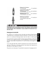
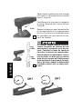
BLEEDER SCREW 3.211.423
*3211423*
77013920000
77013920100
78013920000
81213920000
01.2014

Le agradecemos que se haya decidido por este producto.
Este producto de alta calidad está probado para la competición y se ha desarrollado específi camente para las exigencias de este deporte. Para poder
garantizar los máximos niveles de seguridad y funcionalidad, es imprescindible que el producto se monte correctamente. Por este motivo, es muy importante
que siga las instrucciones del manual de montaje o que se ponga en contacto con su concesionario autorizado. El (cuasi) fabricante y el proveedor de este
producto no se harán responsables del montaje y el uso incorrectos.
¡Muchas gracias!
Wir freuen uns, dass Sie sich für dieses Produkt entschieden haben.
Unser hochwertiges Qualitätsprodukt ist rennerprobt und wurde speziell für sportliche Herausforderungen entwickelt. Eine korrekte Montage des
Produktes ist unerlässlich, um ein Maximum an Sicherheit und Funktionalität gewährleisten zu können. Bitte befolgen Sie daher die Montageanleitung
oder wenden Sie sich an Ihren autorisierten Fachhändler. Für falsche Montage oder Verwendung dieses Produktes kann der (Quasi) Hersteller bzw.
Lieferant nicht zur Verantwortung gezogen werden.
Vielen Dank.
Thank you for choosing this product.
Our high quality product has been tested under racing conditions and was developed specifi cally for use in sports activities. Correct installation of the pro-
duct is essential to ensure that a maximum degree of safety and functionality is achieved. Therefore, please follow the installation instructions or contact
your authorized dealer. The (quasi) manufacturer or supplier cannot be held responsible for products that are incorrectly mounted or inappropriately used.
Thank you.
Grazie per aver scelto questo prodotto.
Questo nostro prodotto di pregiata qualità è collaudato nelle competizioni ed è stato sviluppato specifi camente per gare sportive. Il montaggio corretto del
prodotto è fondamentale per garantirne la massima sicurezza e funzionalità. Rispettare quindi le istruzioni di montaggio o rivolgersi al proprio concessio-
nario autorizzato. Il produttore (detentore del marchio)/fornitore non può essere considerato responsabile per un montaggio o impiego errato del presente
prodotto.aVi ringraziamo per l’attenzione!
Merci d‘avoir porté votre choix sur ce produit.
Notre produit de haute qualité est éprouvé pour les compétitions et a été conçu spécialement pour un usage sportif. Un montage approprié du produit
est indispensable pour garantir une sécurité et une fonctionnalité maximales du véhicule. C‘est pourquoi nous vous invitons à suivre scrupuleusement le
manuel de montage ou à vous adresser à votre revendeur agréé. En cas de montage ou d‘utilisation non conformes de ce produit, le (quasi )constructeur
ou le fournisseur déclinent toute responsabilité.
Merci !
2 ENGLISH
2 ITALIANO
2 FRANCAIS
2 ESPANOL
2 DEUTSCH

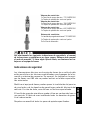
Lieferumfang:
1x Entlüfterschraube 77013920000
1x Staubschutzkappe
Lieferumfang:
1x Entlüfterschraube 78013920000
1x Staubschutzkappe
Lieferumfang:
1x Entlüfterschraube 81213920000
1x Staubschutzkappe
Lesen Sie die folgenden Sicherheitshinweise und die
Bedienungsanleitung sorgfältig durch und heben Sie diese gut auf.
Geben Sie diese Anleitung an andere Nutzer weiter. Sollten
Unklarheiten bestehen, beginnen Sie auf keinen Fall mit Arbeiten an
der Bremsanlage.
Sicherheitshinweise
Arbeiten an der Bremsanlage von Kraftfahrzeugen dürfen nur von aus-
gebildeten und autorisierten Fachleuten durchgeführt werden.
Insbesondere Arbeiten an ABS-Bremsanlagen dürfen nur in einer
autorisierten Fachwerkstätte durchgeführt werden.
Durch Veränderungen an der Bremsanlage können die
Betriebserlaubnis oder auch Garantieansprüche gegen den Hersteller
des Kraftfahrzeugs erlöschen. In Zweifelsfällen ist ein Fachmann zu
Rate zu ziehen.
Die Entlüfterschraube darf nur zu dem bestimmungsgemäßen
Gebrauch eingesetzt werden. In allen anderen Fällen erlischt jeglicher
Anspruch auf Gewährleistung oder Schadenersatz.
Alle angegebenen Anzugsdrehmomente sind genau einzuhalten.
Lieferumfang:
1x Hohl-Entlüfterschraube 77013920100
1x Staubschutzkappe
2x Dichtring
DEUTSCH
3

Die Entlüfterschraube muss normalerweise nicht auseinandergebaut
werden. Sollte es trotzdem einmal vorkommen, dass Ober- und
Unterteil getrennt werden, so müssen diese vorsichtig wieder zusam-
mengeschraubt werden. Dabei ist darauf zu achten, dass es nicht zu
Verschmutzungen innerhalb der Entlüfterschraube kommt. In
Zweifelsfällen wenden Sie sich an den Händler.
Verunreinigungen im Bremssystem können die Funktion der
Entlüfterschraube beeinträchtigen oder zu Ausfällen des
Bremssystems führen. Deshalb ist der Schlauchanschluss durch eine
Staubschutzkappe zu verschließen. Alle Dichtsitze müssen sauber
und unbeschädigt sein.
Bremsflüssigkeit ist sehr ätzend und giftig. Hautkontakt ist unbedingt
zu vermeiden. Bei Arbeiten am Bremssystem ist eine Schutzbrille zu
tragen. Bei Kontakt mit den Augen oder bei Verschlucken suchen Sie
sofort einen Arzt auf. Beachten Sie auch die Sicherheitsratschläge
des jeweiligen Herstellers.
Bremsflüssigkeit ist stark umweltschädlich und muss bei allen
Arbeiten und der Entsorgung entsprechend sorgfältig gehandhabt wer-
den.
Nach Abschluss der Arbeiten ist eine sorgfältige Prüfung der gesam-
ten Bremsanlage auf festen Sitz aller Schrauben und Verbindungen
durchzuführen. Der Ausgleichsbehälter für die Bremsflüssigkeit muss
den korrekten Füllstand aufweisen. Vor Fahrtantritt unbedingt
Probebremsungen im Stand und anschließend im Schritttempo durch-
führen, um zu prüfen, ob der Bremsdruck aufgebaut und
gehalten wird. In Zweifelsfällen darf nicht weiter gefahren werden und
es ist eine Fachwerkstatt zu Rate zu ziehen.
Im Falle einer fehlerhaften oder unsachgemäßen Montage der
Produkte wird keine Haftung übernommen.
DEUTSCH
4

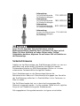
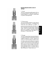
Funktionsweise der
Entlüfterschraube
1. Fahren
Die Entlüfterschraube ist vollständig
geschlossen und dichtet so das
Bremssystem zuverlässig ab. Nur in
diesem Betriebszustand darf das
Fahrzeug bewegt werden.
3. Entlüften
Die Entlüfterschraube ist gerade soweit
geöffnet, dass das integrierte
Rückschlagventil wirken kann (0,5
Umdrehungen geöffnet). Während bei
einem herkömmlichen
Entlüftungsnippel dieser nach jeder
Betätigung des Hauptbremszylinders
wieder geschlossen werden muss, um
das Rückströmen von alter
Bremsflüssigkeit oder Luft zu verhin-
dern, übernimmt die Entlüfterschraube
diese Funktion automatisch. Die
Dichtung verhindert auch hier das
Eindringen von Luft und das Austreten
von Bremsflüssigkeit über das
Schraubengewinde.
2. Befüllen
Die Entlüfterschraube ist soweit geöff-
net, dass Bremsflüssigkeit ungehindert
durchströmen kann (1,5 Umdrehungen
geöffnet). In dieser Stellung ist der
Einsatz von Unterdruckbefüll- oder
Entlüftungssystemen möglich. Durch
die integrierte Dichtung in der
Entlüfterschraube ist das Bremssystem
gegen das Eindringen von Luft durch
das Schraubengewinde wirksam abge-
dichtet.
DEUTSCH
5

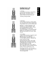
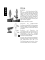
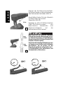
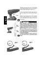
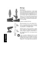
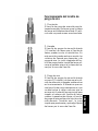
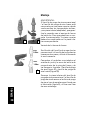
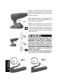
Montage
HINWEIS:
Die Entlüfterschraube/Hohl-
Entlüfterschraube besteht aus einem
Oberteil, in dem die aktiven Bauteile ent-
halten sind, und aus einem Unterteil
(Adapter), das den Anschluss an die
Bremsanlage des Fahrzeugs gewährleis-
tet. Eine korrekte Funktion ist nur in
Kombination des Oberteils mit dem jewei-
ligen Unterteil gegeben.
Entleeren des Bremssystems.
Austausch der herkömmlichen
Entlüfterschraube/Hohl-Entlüfterschraube
durch die neue Entlüfterschraube/Hohl-
Entlüfterschraube; nur passendes Gewinde
verwenden.
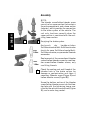
Dichtsitz und Gewinde der
Entlüfterbohrung im Bremssattel auf
Beschädigungen oder Verschmutzung
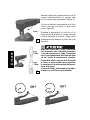
untersuchen und ggf. reinigen
(Entlüfterschraube (Bild 1) und Hohl-
Entlüfterschraube (Bild 2)).
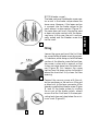
Unterteil der Entlüfterschraube/Hohl-
Entlüfterschraube mit dem entsprechen-
den Drehmoment (Bild 3) in die
Entlüfterbohrung einschrauben; hierzu
eine extralange Stecknuss verwenden.
12
3
max.
10Nm
max.
12Nm
DEUTSCH
6

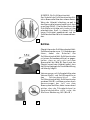
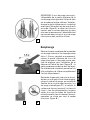
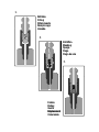
HINWEIS (für Entlüfterschraube):
Das Unterteil der Entlüfterschraube dich-
tet im Bremssattel über den unteren Konus.
Wenn das Unterteil allerdings so weit in
den Bremssattel eingeschraubt wird, dass
es aufliegt (Bild 1 ), berührt der Konus die
Dichtfläche nicht oder nicht mehr mit der
erforderlichen Kraft. In diesem Fall ist
keine Dichtigkeit gewährleistet und die
Entlüfterschraube darf nicht verwendet wer-
den.
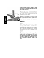
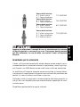
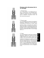
Befüllen
Oberteil der ersten Entlüfterschraube/Hohl-
Entlüfterschraube um ca. 1,5 Umdrehungen
lösen; dabei das Unterteil der
Entlüfterschraube/Hohl-Entlüfterschraube
mit einem Schraubenschlüssel so gegen-
halten, dass es sich nicht aus dem
Bremssattel löst (Bild 2); Damit wird das
Oberteil so weit vom Unterteil gelöst, dass
die Rückschlagkugel die Durchströmöffnung
vollständig freigibt.
Vakuumpumpe mit Auffangbehälter oder
Vakuum-Befüll- und Entlüftungshilfe an
den Schlauchanschluss der
Entlüfterschraube/Hohl-Entlüfterschraube
ansetzen (Bild 3) und Bremssystem durch
Heraussaugen der Luft aus dem
Bremssystem befüllen; dabei immer darauf
achten, dass der Flüssigkeitsstand im
Ausgleichsbehälter nicht unter die
Minimum-Markierung fällt (Bild 4).
1
2
34
DEUTSCH
7

Nach Austritt von Bremsflüssigkeit Oberteil
der Entlüfterschraube/Hohl-
Entlüfterschraube schließen (Bild 1).
Schlauch von der Entlüfterschraube/Hohl-
Entlüfterschraube lösen und Oberteil mit
dem entsprechenden Drehmoment (8Nm)
nochmals festziehen.
Vorgang an allen anderen
Entlüfterschrauben/Hohl-
Entlüfterschrauben wiederholen und
Staubschutzkappen auf die
Schlauchanschlüsse stecken
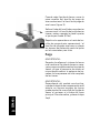
Entlüften
HINWEIS:
Nach einem Neubefüllen des
Bremssystems oder auch nach einem
Austausch der Bremsflüssigkeit ist die
gesamte Bremsanlage sorgfältig zu ent-
lüften, da Lufteinschlüsse im Bremssystem
zu einer verminderten Bremsleistung und
evtl. zu einem vollständigen Ausfall der
Bremse führen können.
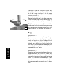
HINWEIS:
Bauartbedingt kann es bei einigen
Bremsanlagen bei geöffnetem
Ausgleichsbehälter zu fontänenartigem
Austritt von Bremsflüssigkeit beim
Betätigen des Hauptbremszylinders kom-
men. Deshalb Deckel lose auflegen!
1
DEUTSCH
8

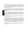
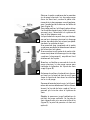
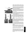
Oberteil der ersten Entlüfterschraube/Hohl-
Entlüfterschraube um ca. eine halbe
Umdrehung lösen; dabei das Unterteil der
Entlüfterschraube/Hohl-Entlüfterschraube
mit einem Schraubenschlüssel so gegenhal-
ten (Bild 1), dass es sich nicht aus dem
Bremssattel löst.
In dieser Position verschließt die
Rückschlagkugel durch die Wirkung der Feder
die Durchströmöffnung gerade noch, so dass
das Bremssystem im drucklosen Zustand
dicht ist.
Es kann also keine Bremsflüssigkeit aus der
Entlüfterschraube/Hohl-Entlüfterschraube
austreten und keine Luft in das Bremssystem
eindringen.
Wird das Oberteil zu weit geöffnet, kann die
Rückschlagfunktion nicht mehr wirken.
Wird es nicht weit genug geöffnet, schlägt
die Kugel am oberen Sitz an (Klackgeräusch)
und läßt keine Flüssigkeit durchströmen.
Auffangbehälter für verbrauchte
Bremsflüssigkeit mit Schlauch an den
Schlauchanschluss der Entlüfterschraube/
Hohl-Entlüfterschraube anstecken (Bild 2).
Hauptbremszylinder betätigen (z.B. durch
Ziehen am Handbremshebel) und dadurch
Bremsflüssigkeit durch die Entlüfterschraube/
Hohl-Entlüfterschraube in das Auffanggefäß
drücken
Handbremshebel lösen. Die Rückschlagkugel
verschließt sofort die Durchströmöffnung
und verbrauchte Bremsflüssigkeit und Luft
können nicht mehr in das Bremssystem
zurückströmen.
Vorgang wiederholen bis gewünschtes
Entlüftungsergebnis erreicht ist.
(austretende Bremsflüssigkeit ist frei von
Luftbläschen (Bild 2), Bremse hat optima-
len Druckpunkt).
1
2
DEUTSCH
9

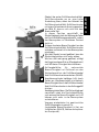
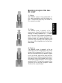
1
Oberteil der Entlüfterschraube/Hohl-
Entlüfterschraube mit dem entsprechen-
den Drehmoment festziehen (Bild 1).
Anschließend festen Sitz des Unterteils
im Bremssattel noch einmal
überprüfen (Bild 2).
Vorgänge an allen Entlüfterschrauben
/Hohl-Entlüfterschrauben des
Bremskreises wiederholen und
Staubschutzkappen auf die
Schlauchanschlüsse stecken.
Nach Abschluss der Arbeiten sorgfältige
Prüfung der gesamten Bremsanlage auf fes-
ten Sitz aller Schrauben und Verbindungen.
Ausgleichsbehälter für Bremsflüssigkeit auf
korrekten Füllstand prüfen.
Vor Fahrtantritt unbedingt Probebremsungen
im Stand und anschließend im Schritttempo
durchführen, um zu prüfen, ob der
Bremsdruck aufgebaut und gehalten wird.
In Zweifelsfällen nicht weiterfahren und
Fachwerkstatt zu Rate ziehen.
2
max.
10Nm
max.
12Nm
DEUTSCH
10

Scope of delivery:
1x bleeder screw 77013920000
1x dust cap
Scope of delivery:
1x bleeder screw 78013920000
1x dust cap
Scope of delivery:
1x bleeder screw 81213920000
1x dust cap
Read the following safety instructions and the owner's manual carefully
and keep it in a safe place. Give this manual to other users as well. If
anything is unclear, do not under any circumstances begin work on the
brake system.
Safety instructions
Work on the brake system of motor vehicles may only be performed by
trained and authorized technicians. In particular, work on ABS brake sys-
tems may only be performed by an authorized specialist workshop.
Changes to the brake system may invalidate the operating approval or
warranty claims against the manufacturer of the vehicle. An expert must
be consulted if there are any questions.
The bleeder screw may only be used as intended. Use in any other man-
ner invalidates warranty or damage claims.
All specified tightening torques must be adhered to precisely..
Scope of delivery:
1x Hollow bleeder screw 77013920100
1x Dust cap
2x Seal ring
ENGLISH
11

The bleeder screw normally does not need to be dismantled. However,
if it should become necessary to separate the upper and lower sections,
they must be screwed together again carefully. Ensure that the inside of
the bleeder screw does not become contaminated. If there are any ques-
tions, consult the dealer.
Contamination in the brake system can impair the function of the blee-
der screw and lead to brake system failure. For this reason, the hose con-
nection must be closed with a dust cap. All sealing seats must be clean
and undamaged.
Brake fluid is highly corrosive and poisonous. It is very important to avoid
skin contact. Goggles must be worn when working on the brake system.
If contact is made with the eyes or if swallowed, consult a physician imme-
diately. Also follow the safety recommendations from the respective
manufacturer.
Brake fluid is hazardous to the environment and must be worked with
and disposed of carefully.
After completing work on the system, carefully check the entire brake
system to ensure that all screws and connections are firmly seated. The
compensating tank for the brake fluid must be filled to the correct level.
Before starting on a trip, it is important that you test the brakes while
the vehicle is standing and then at walking speed to check that braking
pressure is built up and maintained properly. If there is any doubt, do
not continue riding and consult a specialist workshop.
Liability cannot be assumed for products that are mounted incorrectly
or improperly.
ENGLISH
12

Operating principle of the blee-
der screw
1. Riding
The bleeder screw is fully closed and in
this way completely seals the brake sys-
tem. The vehicle may only be moved in
this operating mode.
3. Bleeding
The bleeder screw is opened as far as
necessary for the integrated check valve
to be effective (opened by 0.5 rotations).
While a conventional air release nipple
must be closed again after every activa-
tion of the main brake cylinder to prevent
the return flow of old brake fluid or air,
the bleeder screw performs this function
automatically. The seal also prevents the
intrusion of air and the escape of brake
fluid via the screw thread.
2. Filling
The bleeder screw is opened as far as
necessary to allow the brake fluid to flow
though it freely (opened by 1.5 rotati-
ons). Vacuum filling systems or bleed sys-
tems can be used in this position. The
brake system is protected against the
intrusion of air through the screw thread
by means of the integrated seal in the blee-
der screw.
ENGLISH
13

Assembly
NOTE:
The bleeder screw/hollow bleeder screw
consists of an upper section that contains
the active components, and a lower section
(adapter), which provides the connection
to the brake system of the vehicle. The
unit only functions correctly when the
upper section is combined with the mat-
ching lower section.
Emptying the brake system.
Austausch der herkömmlichen
Entlüfterschraube/Hohl-Entlüfterschraube
durch die neue Entlüfterschraube/Hohl-
Entlüfterschraube; nur passendes Gewinde
verwenden.
Replacement of the conventional bleeder
screws/hollow bleeder screws by new blee-
der screws/hollow bleeder screws; only
use fitting threads.
Check the sealing seat and thread of the
bleeder hole in the brake caliper for
damage or contamination and clean if
necessary (Bleeder screw (Figure 1) and
hollow bleeder screw (Figure 2)).
Screw the bottom section of the bleeder
screw/hollow bleeder screw into the blee-
der hole with the tightening torque spe-
cified by the vehicle manufacturer (Figure
3); use an extra long socket.
12
3
max.
10Nm
max.
12Nm
ENGLISH
14

NOTE (bleeder screw):
The lower section of the bleeder screw crea-
tes a seal in the brake caliper above the
lower cone. However, if the lower section
is screwed into the brake caliper to the
point where it makes contact (Figure 1),
the cone does not touch the sealing area
or does not make contact with the neces-
sary force. In this case, the unit is not pro-
perly sealed and the bleeder screw may
not be used.
Filling
Loosen the upper section of the first blee-
der screw/hollow bleeder screw by approx.
1.5 rotations; while doing so, hold the lower
section of the bleeder screw/hollow blee-
der screw in place with a wrench so that
it does not come loose from the brake cali-
per (Figure 2); this loosens the upper
section from the lower section to the point
where the check ball fully clears the flow
opening.
Connect the vacuum pump with the col-
lection container, or the vacuum filling aid
or bleed aid, to the hose connector of the
bleeder screw/hollow bleeder screw (Figure
3) and fill the brake system by sucking
the air out of the brake system; always
ensure that the fluid level in the compen-
sating tank does not drop below the mini-
mum mark (Figure 4)
34
ENGLISH
15
1
2

After the brake fluid exits, close the upper
section of the bleeder screw/hollow blee-
der screw (Figure 1)
Remove the hose from the bleeder
screw/hollow bleeder screw and retighten
the upper section with the appropriate
tightening torque (8Nm)
Repeat the procedure for all other blee-
der screws/hollow bleeder screws and
place the dust caps on the hose con-
nectors.
Bleeding
NOTE:
After refilling the brake system or after
changing the brake fluid, carefully bleed
the entire brake system because trapped
air in the brake system impairs braking
efficiency and may lead to complete brake
failure.
NOTE:
Depending on the particular design of the
brake system, the brake fluid may squirt
out like a fountain when the compensa-
ting tank is open if the main brake cylin-
der is activated. Therefore, cover it loo-
sely!
1
ENGLISH
16

Loosen the upper section of the first blee-
der screw/hollow bleeder screw by approx.
one half rotation; in doing so, hold the lower
section of the bleeder screw in place using
a wrench (Figure 1) so that it does not come
loose from the brake caliper.
In this position, the check ball just barely
closes the flow opening by means of spring
action, so that the brake system is sealed
when it is not under pressure.
Thus, brake fluid cannot escape from the
bleeder screw/hollow bleeder screw and
air cannot intrude into the brake system.
If the upper section is opened too far, the
check function no longer works effectively.
If it is not opened far enough, the ball stri-
kes against the upper seat (clicking sound)
and prevents fluid from flowing through.
Using a hose, connect the collection con-
tainer for the used brake fluid to the hose
connector of the bleeder screw/hollow
bleeder screw (Figure 2).
Activate the main brake cylinder (e.g. by
pulling on the hand brake lever) and in
this way press brake fluid through the
bleeder screw/hollow bleeder screw into
the collection container.
Release the hand brake lever. The check
ball immediately closes the flow opening
and used brake fluid and air can no lon-
ger flow back into the brake system.
Repeat the procedure until the desired
bleed result is reached (the exiting brake
fluid has no air bubbles (Figure 2); the
brake has the right pressure point).
2
ENGLISH
17
1

ENGLISH
18
1
Tighten the upper section of the bleeder
screw/hollow bleeder screw with the appro-
priate tightening torque (Figure 1).
Finally, check again that the lower section
is firmly seated in the brake caliper (Figure
2).
Repeat the procedures on all bleeder
screws/hollow bleeder screws of the brake
circuit and place dust caps on the hose
connectors
After the work is completed, carefully
check the entire brake system to ensure
that all screws and connections are firmly
seated. Check that the brake fluid in the
compensating tank is at the correct level.
Before starting on a trip, it is important
that you test the brakes while the vehicle
is standing and then at walking speed to
check that brake pressure is built up and
maintained properly.
If there is any doubt, do not continue on
the trip and consult a specialist work-
shop.
2
max.
10Nm
max.
12Nm

ITALIANO
19
Volume della fornitura:
N. 1 Vite di scarico 77013920000
N. 1 Tappo antipolvere
Volume della fornitura:
N. 1 Vite di scarico 78013920000
N. 1 Tappo antipolvere
Volume della fornitura:
N. 1 Vite di scarico 81213920000
N. 1 Tappo antipolvere
Leggere con attenzione il manuale d'uso e le avvertenze per la sicurezza
di seguito riportate e conservarli con cura. Consegnare questo manuale
agli altri utilizzatori. In caso di dubbi, non iniziare i lavori sull'impianto
frenante.
Avvertenze per la sicurezza
I lavori sull'impianto frenante del veicolo devono essere eseguiti esclu-
sivamente da tecnici autorizzati e formati.In particolare, i lavori sugli impi-
anti frenanti con ABS devono essere svolti solo in officine autorizzate.
Le modifiche all'impianto frenante possono annullare la licenza d'eser-
cizio oppure le rivendicazioni di garanzia nei confronti del produttore del
veicolo. In caso di dubbio, consultare un tecnico.
Utilizzare la vite di spurgo solo in modo conforme allo scopo previsto. In
tutti gli altri casi decade qualunque rivendicazione di garanzia o di risar-
cimento danni.
Rispettare rigorosamente le coppie indicate.
Volume della fornitura:
N. 1 Vite di spurgo cava 77013920100
N. 1 Tappo antipolvere
N. 2 Anello di tenuta

Normalmente non risulta necessario smontare la vite di spurgo. Se fosse
ugualmente necessario smontare l'elemento inferiore dall'elemento supe-
riore, montarli nuovamente con attenzione.Fare attenzione che la vite di
spurgo non entri a contatto con impurità. In caso di dubbio, rivolgersi al
rivenditore.
Impurità nel sistema frenante possono pregiudicare la funzione della vite
di spurgo oppure causare guasti al sistema frenante. Per questo motivo,
chiudere il raccordo del tubo con un tappo antipolvere.Tutte le sedi di
tenuta devono essere pulite e prive di danni.
Il fluido dei freni è altamente irritante e velenoso.Evitare assolutamente
il contatto con la pelle. Per i lavori al sistema frenante indossare occhiali
protettivi.In caso di contatto con gli occhi o di ingestione rivolgersi imme-
diatamente a un medico.Rispettare i consigli di sicurezza del produttore
corrispondente.
Il fluido per freni è altamente dannoso per l'ambiente; maneggiare con
attenzione il liquido durante tutti i lavori e lo smaltimento.
Dopo aver terminato il lavoro, controllare con attenzione che tutte le viti
e i raccordi dell'intero impianto frenante siano bene in sede. Il vaso d'espan-
sione per il fluido per freni deve trovarsi sul livello di riempimento cor-
retto. Prima della guida, eseguire test di frenata in folle e a passo d'uomo
per controllare la creazione e il mantenimento della pressione di frenata.
In caso di dubbi, interrompere la guida e rivolgersi a un'officina specia-
lizzata.
In caso di montaggio errato o non conforme dei prodotti il produttore non
si assume alcuna responsabilità.
ITALIANO
20
La pagina si sta caricando...
La pagina si sta caricando...
La pagina si sta caricando...
La pagina si sta caricando...
La pagina si sta caricando...
La pagina si sta caricando...
La pagina si sta caricando...
La pagina si sta caricando...
La pagina si sta caricando...
La pagina si sta caricando...
La pagina si sta caricando...
La pagina si sta caricando...
La pagina si sta caricando...
La pagina si sta caricando...
La pagina si sta caricando...
La pagina si sta caricando...
La pagina si sta caricando...
La pagina si sta caricando...
La pagina si sta caricando...
La pagina si sta caricando...
La pagina si sta caricando...
La pagina si sta caricando...
La pagina si sta caricando...
-
 1
1
-
 2
2
-
 3
3
-
 4
4
-
 5
5
-
 6
6
-
 7
7
-
 8
8
-
 9
9
-
 10
10
-
 11
11
-
 12
12
-
 13
13
-
 14
14
-
 15
15
-
 16
16
-
 17
17
-
 18
18
-
 19
19
-
 20
20
-
 21
21
-
 22
22
-
 23
23
-
 24
24
-
 25
25
-
 26
26
-
 27
27
-
 28
28
-
 29
29
-
 30
30
-
 31
31
-
 32
32
-
 33
33
-
 34
34
-
 35
35
-
 36
36
-
 37
37
-
 38
38
-
 39
39
-
 40
40
-
 41
41
-
 42
42
-
 43
43


KTM 78013920000 Manuale del proprietario
- Tipo
- Manuale del proprietario
- Questo manuale è adatto anche per
in altre lingue
- français: KTM 78013920000 Le manuel du propriétaire
- español: KTM 78013920000 El manual del propietario
- Deutsch: KTM 78013920000 Bedienungsanleitung