
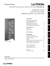
Wallbox Input Closure Interface
OMX-WCI
PELV (Class 2: USA) Devices 24 V 200 mA
R
Chinese
English
Español Français
Português
NederlandsDeutsch Italiano
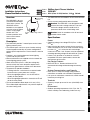
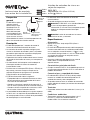
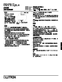
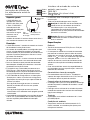
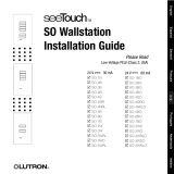
Overview
The OMX-WCI is for use
with GRAFIK 5000/6000/
7000 series systems. The
OMX-WCI mounts
behind the user-supplied
switch to select or adjust
scenes in up to eight
control units. The
interface provides from
two to seven contact
closure inputs.
Description
• The OMX-WCI provides 7 control inputs to the Lutron
lighting control system.
• The control inputs can be set up to simulate existing
Lutron keypad functionality or custom-configured to
project-specific requirements. Please contact Lutron for
details.
• Provides 1-way interface between Lutron lighting
system and an input switch.
• Mounts behind the user-supplied switch to control the
Lutron lighting control system.
• Works with a PELV (Class 2: USA) low-voltage dry
contact switch that meets the power requirements
found in the Specifications section of this document.
• The power LED provides feedback:
- Flashing indicates a miswire on the communication
link or that the system processor is off-line.
- When the nightlight option is set, the LED will be
steadily lit when polled.
- When the nightlight option bit is cleared, the LED will
not be lit when polled.
• The recommended wallbox depth is 61 mm (2.5 in.).
The wallbox depth requirements vary with the depth of
the switch being used.
• The OMX-WCI uses one address on the communication
link.
• Can be custom-configured for other functions.
Caution: The OMX-WCI is not designed to work
with the line/mains voltage switches. Use with
line/mains voltage switches could result in
premature failure of the switch being used.
Caution: Install in accordance with all local and
national electric codes.
Specifications
Power
• Operating voltage: low-voltage PELV (Class 2: USA),
24 V .
• Input switch or dry contact switch closure must have
solid-state outputs with an on-state saturation voltage
less than 1 V at 1 mA and an off-state leakage
current of less than 1 mA. Outputs must be capable of
switching operating voltage for desired life of system.
• If there is any question as to whether a switch is
compatible with these specifications, contact the
manufacturer of the switch.
Key Design Features
• Meets IEC 801-2. Tested to withstand 15 kV
electrostatic discharge without damage or memory
loss.
System Communications and Capacity
• PELV (Class 2: USA) low-voltage wiring connects
wallstations to control units and other components.
• Link up to 32 wallstations, control units, and/or control
interfaces per wiring link.
Terminals
• Capacity: Accept up to two 1.0 mm
2
(#18 AWG) wires
typical.
Environment
• Ambient operating temperature 0-40 °C (32-104 °F),
0-90% humidity, non-condensing. Indoor use only.
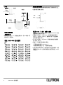
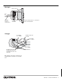
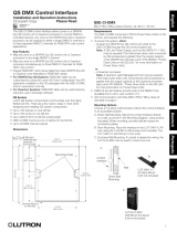
Installation Instructions
Please Read before Installing
Input wiring
harness
Addressing switches
Power
LED
5000TM
6000®
7000TM

2 OMX-WCI Installation Instructions
R
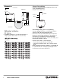
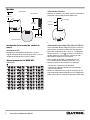
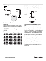
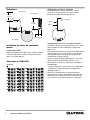
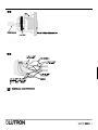
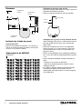
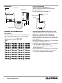
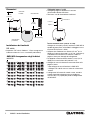
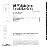
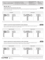
Dimensions
Wallstation Installation
DIP Switches
• Set Address Switches 1-5 to give the wallstation a
unique system address from 1 to 32 (see chart).
12345
ON
12345
ON
12345
ON
12345
ON
1
2
3
4
12345
ON
12345
ON
12345
ON
12345
ON
5
6
7
8
12345
ON
12345
ON
12345
ON
12345
ON
9
10
11
12
12345
ON
12345
ON
12345
ON
12345
ON
13
14
15
16
12345
ON
12345
ON
12345
ON
12345
ON
17
18
19
20
12345
ON
12345
ON
12345
ON
12345
ON
21
22
23
24
12345
ON
12345
ON
12345
ON
12345
ON
25
26
27
28
12345
ON
12345
ON
12345
ON
12345
ON
29
30
31
32
OMX-WCI Addressing
ADDRESS
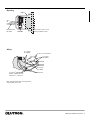
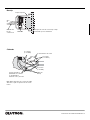
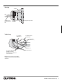
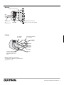
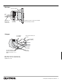
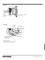
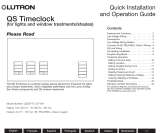
Contact Closure Wiring
• Connect the desired input(s) and common wires to the
switch provided by others.
• Cap off unused input wires.
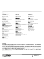
Low-Voltage PELV (Class 2: USA) Wiring
Use low-voltage PELV (Class 2: USA) wiring to daisy-
chain the OMX-WCI to the processor panel.
• Use two 2.5 mm
2
(#12 AWG) conductors for common
(terminal 1) and 24 V (terminal 2). These will not fit
into terminals; see opposite for connection details.
• Use one shielded, twisted pair 1.0 mm
2
(#18 AWG) wires
for data link (terminals 3 and 4).
• Connect drain/shield as shown opposite.
- Do not connect ground/earth to OMX-WCI.
- Connect the bare drain wires and cut off the outside
shield.
• Make connections inside the wallbox, in a switchbox, or
in a junction box with a maximum wire length of 2.5 m
(8 feet) from the link to the OMX-WCI.
75 mm
(2 15/16”)
119 mm
(4 11/16”)
75 mm
(2 15/16”)
Front View
Back View
Side View
20 mm (13/16”)
Switch
Common
Input 1

R
Communication
link wiring
OMX-WCI
Wallbox
Mounting
Wiring
To other control interfaces
(2) 2.5 mm
2
(#12 AWG )
(2) 2.5 mm
2
(#12 AWG )
(2) 1.0 mm
2
(#18 AWG)
twisted, shielded pair from
terminals 3 to 3 and 4 to 4
Drain wires
Note: Use appropriate wire connecting devices
as specified by local codes.
4 3 2 1
(2) 1.0 mm
2
(#18 AWG)
OMX-WCI Installation Instructions 3
Low-voltage contact closure
switch provided by others

R
LIMITED WARRANTY
Lutron will, at its option, repair or replace any unit that is defective in materials or manufacture within one year after purchase. For warranty service,
return unit to place of purchase or mail to Lutron at 7200 Suter Rd., Coopersburg, PA 18036-1299, postage pre-paid.
This warranty is in lieu of all other express warranties, and the implied warranty of merchantability is limited to one year from purchase. This warranty
does not cover the cost of installation, removal or reinstallation, or damage resulting from misuse, abuse, or improper or incorrect repair, or damage
from improper wiring or installation. This warranty does not cover incidental or consequential damages. Lutron’s liability on any claim for damages
arising out of or in connection with the manufacture, sale, installation, delivery, or use of the unit shall never exceed the purchase price of the unit.
This warranty gives you specific legal rights, and you may also have other rights which vary from state to state. Some states do not allow limitations on
how long an implied warranty lasts, so the above limitation may not apply to you. Some states do not allow the exclusion or limitation of incidental or
consequential damages, so the above limitation or exclusion may not apply to you.
Lutron, the sunburst logo, GRAFIK Eye, and GRAFIK 6000 are registered trademarks and GRAFIK systems, GRAFIK 5000, and GRAFIK 7000 are
trademarks of Lutron Electronics Co., Inc.
© 2006 Lutron Electronics Co., Inc.
Internet: www.lutron.com
E-mail: [email protected]
WORLD HEADQUARTERS
Lutron Electronics Co., Inc.
7200 Suter Road, Coopersburg, PA 18036-1299
USA
TEL +1.610.282.3800
FAX +1.610.282.1243
Toll-Free 1.888.LUTRON1
Technical Support 1.800.523.9466
EUROPEAN HEADQUARTERS
Lutron EA Ltd.
6 Sovereign Close, London,
E1W 3JF United Kingdom
TEL +44.(0)20.7702.0657
FAX +44.(0)20.7480.6899
FREEPHONE (UK) 0800.282.107
Technical support +44.(0)20.7680.4481
WORLDWIDE OFFICES
Brazil
Lutron BZ do Brasil Ltda.
AV, Brasil, 239, Jardim America,
Sao Paulo-SP, CEP: 01431-000, Brasil
TEL +55.11.3885.5152
FAX +55.11.3887.7138
France
Lutron LTC, S.A.R.L.
90 rue de Villiers, 92300 Levallois-Perret France
TEL +33.(0)1.41.05.42.80
FAX +33.(0)1.41.05.01.80
FREEPHONE 0800.90.12.18
Germany
Lutron Electronics GmbH, Landsberger Allee 201, 13055
Berlin, Germany
TEL +49.(0)30.9710.4590
FAX +49.(0)30.9710.4591
FREEPHONE 00800.5887.6635
Italy
Lutron LDV, S.r.l.
FREEPHONE 800.979.208
Spain, Barcelona
Lutron CC, S.R.L.
Gran Via Carlos III, 84, planta 3a, 08028,
Barcelona, Spain
TEL +34.93.496.57.42
FAX +34.93.496.57.01
FREEPHONE 0900.948.944
Spain, Madrid
Lutron CC, S.R.L.
Calle Orense, 85, 28020 Madrid, Spain
TEL +34.91.567.84.79
FAX +34.91.567.84.78
FREEPHONE 0900.948.944
China, Beijing
Lutron GL Ltd. Beijing Representative Office
5th Floor, China Life Tower, No. 16 Chaowai Street,
Chaoyang District, Beijing 100020 China
TEL +86.10.5877.1818
FAX +86.10.5877.1816
China, Guangzhou
Lutron GL Ltd. Guangzhou Representative Office
Suite A09, 23/F Tower A, Centre Plaza,
161 Lin He Xi Lu, Tian He District, Guangzhou 510620
China
TEL +86.20.2885.8266
FAX +86.20.2885.8366
China, Shanghai
Lutron GL Ltd. Shanghai Representative Office
Suite 07, 39th Floor, Plaza 66,
1266 Nan Jing West Road, Shanghai, 200040 China
TEL +86.21.6288.1473
FAX +86.21.6288.1751
Hong Kong
Lutron GL Ltd.
Room 2808, 28/F, 248 Queen's Road East,
Wanchai, Hong Kong
TEL +852.2104.7733
FAX +852.2104.7633
Japan
Lutron Asuka Co. Ltd.
No. 16 Kowa Building, 4F, 1-9-20, Akasaka,
Minato-ku, Tokyo 107-0052 Japan
TEL +81.3.5575.8411
FAX +81.3.5575.8420
Singapore
Lutron GL Ltd.
15 Hoe Chiang Road, #07-03 Euro Asia Centre,
Singapore 089316
TEL +65.6220.4666
FAX +65.6220.4333
Asia Technical Hotlines
Northern China: 10.800.712.1536
Southern China: 10.800.120.1536
Hong Kong: 800.901.849
Singapore: 800.120.4491
Taiwan: 00.801.137.737
Thailand: 001.800.120.665853
Other Areas: +65.6220.4666
Lutron Electronics Co., Inc.
Made and printed in U.S.A. 2/06
P/N 030-827 Rev. D

Interfaz de entradas de cierre en
cajas de empotrar
OMX-WCI
Dispositivos
PELV (Clase 2: EE.UU.)
de 24 V 200 mA
R
Español
Perspectiva
general
El OMX-WCI es para su
uso con sistemas
GRAFIK de las series
5000/6000/7000. El
OMX-WCI se instala
detrás del interruptor
suministrado para que
el usuario seleccione o
ajuste escenas en hasta
ocho unidades de control. La interfaz proporciona de
dos a siete entradas de cierre de contacto.
Descripción
• El OMX-WCI proporciona 7 entradas de control al
sistema de control de iluminación de Lutron.
• Las entradas de control se pueden configurar para
simular las funciones de teclados Lutron o se pueden
personalizar para requisitos específicos del proyecto.
Consulte con Lutron para más detalles.
• Proporciona una interfaz unidireccional entre el sistema
de control de iluminación de Lutron y un interruptor de
entrada.
• Se monta detrás del interruptor suministrado por el
cliente para controlar el sistema de control de
iluminación de Lutron.
• Funciona con un interruptor PELV (Clase 2: EE.UU.) de
bajo voltaje y contacto seco que cumpla con los
requisitos de potencia que figuran en el apartado
Especificaciones de este documento.
• El LED de alimentación indica lo siguiente:
- El parpadeo indica un cableado incorrecto en el bus
de comunicación o que el procesador del sistema
está fuera de funcionamiento
- Cuando se selecciona la opción de luz nocturna, el
LED se ilumina fijamente al hacer la llamada selectiva
- Cuando se elimina la opción de luz nocturna, el LED
no se ilumina al hacer la llamada selectiva.
• La profundidad recomendada para la caja de empotrar
es de 61 mm. Los requisitos de profundidad de la caja
de montaje pueden variar en función de la profundidad
del interruptor que se esté utilizando.
• El OMX-WCI utiliza una dirección en el bus de
comunicaciones.
• Se puede configurar para otras funciones.
Atención: El OMX-WCI no ha sido diseñado para
su uso con interruptores generales de
alimentación. El uso con estos interruptores puede
producir un fallo prematuro del interruptor
utilizado.
Atención: Instalar de acuerdo con las normas
eléctricas locales y nacionales.
Especificaciones
Alimentación
• Voltaje de servicio: : bajo voltaje PELV (Clase 2:
EE.UU.), 24 V .
• El cierre del interruptor de entrada o del interruptor de
contacto seco debe tener una salida de estado sólido,
con un voltaje de saturación inferior a 1 V a 1 mA y
una corriente de fuga inferior a 1 mA. Las salidas deben
ser capaces de conmutar el voltaje de servicio
requerido en el sistema.
• Consultar al fabricante del dispositivo en caso de
dudas sobre su compatibilidad con estas
especificaciones.
Características principales de diseño
• Cumple la norma IEC 801-2. Se ha probado que resiste
una descarga electrostática de 15 kV sin sufrir daños ni
pérdidas de memoria.
Comunicaciones y capacidad del sistema
• El cableado PELV (Clase 2: EE.UU.) de bajo voltaje
conecta las unidades de control de pared con las
unidades de control y otros componentes.
• Se pueden conectar hasta 32 unidades de control de
pared, unidades de control y/o interfaces de control por
cada enlace.
Terminales
• Capacidad: admite hasta dos cables de 1,0 mm
2
(nº 18
AWG).
Condiciones ambientales
• Temperatura ambiente de funcionamiento 0-40 °C
(32-104 °F), 0-90% de humedad ambiente, sin
condensación. Uso en interiores solamente.
Instrucciones de montaje
Leer antes de la instalación
Cables de
entradas
digitales
Asignación de
direcciones a los
interruptores
LED de
alimentación
5000TM
6000®
7000TM

2 Instrucciones de instalación del OMX-WCI
R
Medidas
Instalación de la unidad de control de
pared
Interruptores DIP
• Configure los interruptores de dirección 1-5 para
asignar una dirección de sistema única entre 1 y 32 a la
unidad de control de pared. (véase cuadro).
12345
ON
12345
ON
12345
ON
12345
ON
1
2
3
4
12345
ON
12345
ON
12345
ON
12345
ON
5
6
7
8
12345
ON
12345
ON
12345
ON
12345
ON
9
10
11
12
12345
ON
12345
ON
12345
ON
12345
ON
13
14
15
16
12345
ON
12345
ON
12345
ON
12345
ON
17
18
19
20
12345
ON
12345
ON
12345
ON
12345
ON
21
22
23
24
12345
ON
12345
ON
12345
ON
12345
ON
25
26
27
28
12345
ON
12345
ON
12345
ON
12345
ON
29
30
31
32
Direccionamiento del OMX-WCI
DIRECCIÓN
Cableado del Contacto
• Conecte las entradas y los cables comunes deseados al
interruptor suministrado por otros fabricantes.
• Corte los cables de entrada no utilizados.
Cableado de bajo voltaje PELV (Clase 2: EE.UU.)
Utilice cableado de bajo voltaje PELV (Clase 2: EE.UU.)
para conectar en cadena el OMX-WCI al procesador.
• Utilice dos conductores de 2,5 mm2 (nº 12 AWG) para
común (terminal 1) y 24 V (terminal 2). Estos no se
pueden acoplar en los terminales; consulte el lado
opuesto de la página para más detalles.
• Utilice un par apantallado y trenzado de 1,0 mm
2
(nº 18 AWG) para bus de datos (terminales 3 y 4).
• Conecte la malla como se indica en el otro lado.
- No conecte la tierra/masa al OMX-WCI.
- Conecte los cables de pantalla sin revestimiento y
corte la malla externa.
• Realice las conexiones en la caja de montaje o en una
caja de conexión o de distribución con una longitud de
cable máxima de 2,5 m desde la conexión al OMX-WCI.
75 mm
(2 15/16”)
119 mm
(4 11/16”)
75 mm
(2 15/16”)
Vista frontal
Vista posterior
Vista lateral
20 mm (13/16”)
Interruptor
Común
Entrada 1

R
Cableado del
bus de
comunicación
OMX-WCI
Montaje
Cableado
A otras interfaces de control
(2) 2,5 mm
2
(nº 12 AWG )
(2) 2,5 mm
2
(nº 12 AWG )
(2) pares trenzados y
apantallados de 1,0 mm
2
(nº 18 AWG) de los
terminales 3 al 3 y del 4 al 4
Cables de
drenaje
Nota: Utilice dispositivos de conexión de cables
adecuados, según se especifica en las normas
locales.
4 3 2 1
(2) 1,0 mm
2
(nº 18 AWG)
Instrucciones de instalación del OMX-WCI 3
Interruptor de cierre de contacto bajo voltaje
suministrado por otros fabricantes
Caja de empotrar

R
GARANTÍA LIMITADA
A su juicio, Lutron procederá a la reparación o a la sustitución de cualquier unidad que presente defectos de material o de fabricación durante un año
a partir de la fecha de compra. Para reclamaciones en garantía deberá devolver la unidad al distribuidor o oficina Lutron donde la haya adquirido o
enviarla por correo a portes pagados a Lutron, 7200 Suter Rd., Coopersburg, PA 18036-1299.
Esta garantía sustituye cualquier otra garantía expresa; la garantía de comercialización que implica está limitada a un año a partir de la fecha de
compra. Esta garantía no cubre los gastos de instalación, desmontaje o reinstalación, los daños que se deriven del mal uso, abuso o de reparaciones
inadecuadas o incorrectas ni los daños ocasionados por el cableado o la instalación no apropiados. Esta garantía no cubre daños fortuitos o
secundarios. En caso de reclamaciones causadas por o en relación con la fabricación, la venta, la instalación, la entrega o el uso de la unidad, la
responsabilidad de Lutron nunca excederá el precio de adquisición de la unidad.
Esta garantía le otorga derechos legales específicos. Sin embargo, puede tener otros derechos que pueden variar de un país a otro. Algunos países
no permiten limitaciones en la duración de la garantía implícita, por lo que la limitación arriba descrita puede no ser aplicable en su caso. Algunos
países no permiten la exclusión o las limitaciones de daños fortuitos o secundarios, por lo que la limitación o exclusión arriba descrita puede no ser
aplicable en su caso.
Lutron, su logotipo, GRAFIK Eye, y GRAFIK 6000 son marcas registradas y GRAFIK systems, GRAFIK 5000, y GRAFIK 7000 son marcas propiedad
de Lutron Electronics Co., Inc.
© 2006 Lutron Electronics Co., Inc.
Internet: www.lutron.com
E-mail: [email protected]
CENTRAL INTERNACIONAL
Lutron Electronics Co., Inc.
7200 Suter Road, Coopersburg, PA 18036
TEL +1.610.282.3800
FAX +1.610.282.1243
Teléfono gratuito 1.888.LUTRON1
Soporte técnico 1.800.523.9466
CENTRAL PARA EUROPA
Lutron EA Ltd.
6 Sovereign Close, London,
E1W 3JF United Kingdom
TEL +44.(0)20.7702.0657
FAX +44.(0)20.7480.6899
TELÉFONO GRATUITO (R.U.) 0800.282.107
Soporte técnico +44.(0)20.7680.4481
DELEGACIONES INTERNACIONALES
Brasil
Lutron BZ do Brasil Ltda.
AV, Brasil, 239, Jardim America,
Sao Paulo-SP, CEP01431-000, Brasil
TEL +55.11.3885.5152
FAX +55.11.3887.7138
Francia
Lutron LTC, S.A.R.L.
90 rue de Villiers, 92300 Levallois-Perret France
TEL +33.(0)1.41.05.42.80
FAX +33.(0)1.41.05.01.80
TELÉFONO GRATUITO 0800.90.12.18
Alemania
Lutron Electronics GmbH, Landsberger Allee 201, 13055
Berlin, Germany
TEL +49.(0)30.9710.4590
FAX +49.(0)30.9710.4591
TELÉFONO GRATUITO 00800.5887.6635
Italia
Lutron LDV S.r.l.
TELÉFONO GRATUITO 800.979.208
España, Barcelona
Lutron CC, S.R.L.
Gran Via del Carlos III, 84, planta 3a, 08028,
Barcelona, Spain
TEL +34.93.496.57.42
FAX +34.93.496.57.01
TELÉFONO GRATUITO 0900.948.944
España, Madrid
Lutron CC, S.R.L.
Calle Orense, 85, 28020 Madrid, España
TEL +34.91.567.84.79
FAX +34.91.567.84.78
TELÉFONO GRATUITO 0900.948.944
China, Pekín
Lutron GL Ltd. Beijing Representative Office
5th Floor, China Life Tower, No. 16 Chaowai Street,
Chaoyang District, Beijing 100020 China
TEL +86.10.5877.1818
FAX +86.10.5877.1816
China, Guangzhou
Lutron GL Ltd. Guangzhou Representative Office
Suite A09, 23/F Tower A, Center Plaza,
161 Lin He Xi Lu, Tian He District, Guangzhou 510620
China
TEL +86.20.2885.8266
FAX +86.20.2885.8366
China, Shanghai
Lutron GL Ltd. Shanghai Representative Office
Suite 07, 39th Floor, Plaza 66,
1266 Nan Jing West Road, Shanghai, 200040 China
TEL +86.21.6288.1473
FAX +86.21.6288.1751
Hong Kong
Lutron GL Ltd.
Room 2808, 28/F, 248 Queen's Road East,
Wanchai, Hong Kong
TEL +852.2104.7733
FAX +852.2104.7633
Japón
Lutron Asuka Co. Ltd.
No. 16 Kowa Building, 4F, 1-9-20, Akasaka,
Minato-ku, Tokyo 107-0052 Japan
TEL +81.3.5575.8411
FAX +81.3.5575.8420
Singapur
Lutron GL Ltd.
15 Hoe Chiang Road, #07-03 Euro Asia Centre, Singapur
089316
TEL +65.6220.4666
FAX +65.6220.4333
Servicio técnico telefónico en Asia
China Norte: 10.800.712.1536
China Sur: 10.800.120.1536
Hong Kong: 800.901.849
Singapur: 800.120.4491
Taiwan: 00.801.137.737
Tailandia: 001.800.120.665853
Otras áreas: +65.6220.4666
Lutron Electronics Co., Inc.
Redactado e impreso en EE.UU. 2/06
P/N 030-827 Rev. D

Tasterschnittstelle für UP-Dosen
OMX-WCI
Schutzkleinspannungsgeräte (Klasse 2: USA)
24 V 200 mA
R
Deutsch
Übersicht
Das OMX-WCI kann in
GRAFIK-Systemen der
Serie 5000/6000/7000
eingesetzt werden. Das
OMX-WCI wird hinter
einem konventionellen
Schalter (für Niedervolt)
montiert, und dient zum
Auswählen oder Steuern
von Lichtszenen in bis zu
acht Steuerstellen. Das Interface stellt dem Lutron-
Lichtsteuersystem zwei bis sieben Steuereingänge zur
Verfügung.
Beschreibung
• Das OMX-WCI stellt dem Lutron-Lichtsteuersystem 7
Steuereingänge zur Verfügung.
• Die Steuereingänge können so eingestellt werden, dass
sie die Funktionalität vorhandener Lutron-Bedienstellen
simulieren, oder sie können nach projektspezifischen
Anforderungen individuell eingestellt werden. Für
Einzelheiten setzen Sie sich bitte mit Lutron in
Verbindung.
• Stellt eine unidirektionale Schnittstelle zwischen Lutron-
Lichtsteuersystemen und einem Schalter dar.
• Wird hinter dem vom Benutzer gelieferten Schalter
montiert, und dient zum Steuern des Lutron-
Lichtsteuersystems.
• Arbeitet mit einem Schutzkleinspannungs-Schalter
(Klasse 2: USA), der den Leistungsanforderungen im
Spezifikationsabschnitt dieses Dokuments entspricht.
• Die Netzspannungs-LED dient zur Rückmeldung:
-Eine blinkende LED zeigt an, dass eine fehlerhafte
Verdrahtung des Kommunikationslinks vorliegt oder
der Systemprozessor offline ist.
-Ist die Nachtlicht-Option aktiviert, bleibt die LED
während der Kommunikation mit dem Prozessor
ständig eingeschaltet.
-Ist die Nachtlicht-Option inaktiv, wird die LED während
der Kommunikation mit dem Prozessor nicht
eingeschaltet.
• Empfohlene Unterputzdosentiefe 61 mm. Die
Unterputzdosentiefe kann je nach der Tiefe des
verwendeten Schalters unterschiedlich sein.
• Das OMX-WCI verwendet eine Adresse auf dem
Kommunikationslink.
• Kann nach Wunsch für andere Funktionen konfiguriert
werden.
Vorsicht: Das OMX-WCI ist nicht für
Netzspannungsschalter bestimmt. Die Benutzung
von Netzspannungsschaltern kann zur vorzeitigen
Beschädigung des benutzten Schalters führen.
Vorsicht: Bei der Installation sind alle geltenden
Verkabelungsvorschriften einzuhalten.
Spezifikationen
Spannung
• Betriebsspannung: Schutzkleinspannung (Klasse 2:
USA), 24 V .
• Der Eingangsschalter bzw. Schalter mit potentialfreien
Kontakten muss über einen Ausgang mit einer
Sättigungsspannung unterhalb von 1 V im
Durchlasszustand bei 1 mA und einem Kriechstrom
unterhalb von 1 mA im Sperrzustand verfügen. Die
Ausgänge müssen die Betriebsspannung während der
gesamten Lebensdauer des Systems schalten können.
• Falls Sie sich nicht sicher sind, ob ein Schalter mit
diesen Daten kompatibel ist, setzen Sie sich bitte mit
dem Gerätehersteller des Schalters in Verbindung.
Wichtigste Designmerkmale
• Entspricht den Anforderungen in IEC 801-2. Kann
elektrostatischen Entladungen von bis zu 15 kV ohne
Beschädigungen oder Speicherverluste widerstehen.
Systemkommunikation und Kapazität
• Die Bedienstellen sind durch Schutzkleinspannungs-
Verkabelung (Klasse 2: USA) mit den Steuerstellen und
anderen Komponenten verbunden.
• In einem Verkabelungs-Link können bis zu 32
Bedienstellen, Steuerstellen und/oder Steuer-
Schnittstellen miteinander verbunden werden.
Anschlussklemmen
• Kapazität: Typischerweise bis zu zwei 1,0-mm
2
-
Leitungen (AWG Nr. 18).
Umgebung
• Zulässige Umgebungstemperatur: 0-40 °C, zulässiger
Feuchtigkeitsgehalt der Luft: 0-90%, nicht
kondensierend. Nur für Innenräume.
Installationsanweisungen
Bitte lesen Sie diese
Anweisungen vor der Installation
Kabelsatz
Eingangsklemmen
Adressenschalter
Netzspannungs-LED
5000TM
6000®
7000TM

2 OMX-WCI Installationsanweisungen
R
Abmessungen
Installation der Bedienstelle
DIP-Schalter
• Stellen Sie Adressen-DIP-Schalter 1-5 so ein, dass die
Bedienstelle eine nur einmal vergebene Systemadresse
von 1 bis 32 erhält (siehe Tabelle).
12345
ON
12345
ON
12345
ON
12345
ON
1
2
3
4
12345
ON
12345
ON
12345
ON
12345
ON
5
6
7
8
12345
ON
12345
ON
12345
ON
12345
ON
9
10
11
12
12345
ON
12345
ON
12345
ON
12345
ON
13
14
15
16
12345
ON
12345
ON
12345
ON
12345
ON
17
18
19
20
12345
ON
12345
ON
12345
ON
12345
ON
21
22
23
24
12345
ON
12345
ON
12345
ON
12345
ON
25
26
27
28
12345
ON
12345
ON
12345
ON
12345
ON
29
30
31
32
OMX-WCI Adressenzuweisung
ADRESSE
Verkabelung der potentialfreien Kontakte
• Den (die) gewünschten Eingang (Eingänge) an den
Schalter (Produkt eines andren Herstellers) anschließen.
• Nicht benutzte Leiter mit einer Klemme versehen oder
abschneiden.
Schutzkleinspannungs-Verkablung (Klasse 2:
USA)
Für den Anschluss zwischen dem OMX-WCI und dem
Prozessorschrank ist eine Schutzkleinspannungs-
Verkabelung (Klasse 2: USA) in Serienschaltung (Daisy-
Chain) zu verlegen.
• Zwei 2,5-mm
2
-Leiter (AWG Nr. 12) für Masse (Klemme 1)
und 24 V (Klemme 2) verwenden. Die Leiter passen
nicht in die Klemmen; siehe Abbildung gegenüber für
Einzelheiten zum Anschluss.
• Ein abgeschirmtes, verdrilltes 1,0-mm
2
-Leitungspaar
(AWG Nr. 18) als Datenverbindung (Klemmen 3 und 4)
verwenden.
• Die Abschirmung wie gegenüber abgebildet
anschließen.
- Das OMX-WCI nicht mit Masse/Erde verbinden.
- Die abisolierten Schirmleitungen anschließen und die
äußere Abschirmung abschneiden.
• Das OMX-WCI muss innerhalb der UP-Dose, in einem
Schaltkasten oder in einer Verteilerdose an die
Busleitung angeschlossen werden, wobei der Abstand
von der Busleitung zum OMX-WCI höchstens 2,5 m
betragen darf.
75 mm
119 mm
75 mm
Vorderansicht
Rückansicht
Seitenansicht
20 mm
Schalter
Korrespondierend
Eingang 1

R
Verkabelung der
Kommunikationsl
inks
OMX-WCI
UP-Dose
Montage
Verdrahtung
An andere Steuer-
Schnittstellen
(2) 2,5 mm
2
(AWG Nr. 12 )
(2) 2,5 mm
2
(AWG Nr. 12 )
2x 1,0 mm
2
(AWG Nr. 18)
verdrillte geschirmte
Doppelleitung von Klemmen
3 an 3 und 4 an 4
Schirmleitungen
Hinweis: Nur den örtlichen Vorschriften
entsprechende, geeignete Kabelverbinder
verwenden.
4 3 2 1
(2) 1,0 mm
2
(AWG Nr. 18)
OMX-WCI Installationsanweisungen 3
Niederspannungsschalter

R
BESCHRÄNKTE GEWÄHRLEISTUNG
Lutron verpflichtet sich, während des ersten Jahres ab Verkauf unentgeltlich etwaige Mängel, die auf Material- oder Fabrikationsfehler zurückzuführen
sind, zu beseitigen oder nach eigener Wahl mangelhafte Teile zu ersetzen oder nachzubessern. Schicken Sie die Einheit im Garantiefall an Ihren
Händler oder an Lutron, 7200 Suter Rd., Coopersburg, PA 18036-1299, portofrei zurück.
Diese Garantie ersetzt jede andere ausdrückliche oder eine Schlussfolgerung zulassende Garantie. Die die Schlussfolgerung zulassende Garantie der
Wiederverkäuflichkeit ist auf ein Jahr ab Kaufdatum begrenzt. Installations-, Demontage- und Reinstallationskosten sowie Beschädigungen infolge
missbräuchlicher oder falscher Verdrahtung und fehlerhafter Isolation sind von der Garantie ausgeschlossen. Unmittelbare oder Folgeschäden sind von
der Garantie ausgeschlossen. Lutrons Haftung für Schäden in Zusammenhang mit der Herstellung, dem Verkauf, der Installation, der Lieferung oder
der Anwendung der Einheit ist auf den Kaufpreis der Einheit beschränkt.
Durch diese Garantie werden Sie mit gewissen Rechten ausgestattet. Außerdem können Sie in diesem Zusammenhang auch andere Rechte haben,
die von Staat zu Staat unterschiedlich sind. In einigen Staaten darf die Zeitdauer einer indirekten Garantie nicht begrenzt werden. In einigen Staaten ist
es unzulässig, unmittelbare oder Folgeschäden auszuschließen oder zu begrenzen. Daher ist es möglich, dass obige Ausnahmen und Begrenzungen
für Sie nicht gültig sind.
Lutron, das Sunburst-Logo, GRAFIK Eye und GRAFIK 6000 sind eingetragene Warenzeichen, und GRAFIK systems, GRAFIK 5000 und GRAFIK 7000
sind Warenzeichen von Lutron Electronics Co., Inc.
© 2006 Lutron Electronics Co., Inc.
Internet: www.lutron.com
E-Mail: [email protected]
WELTWEITE ZENTRALE
Lutron Electronics Co., Inc.
7200 Suter Road, Coopersburg, PA 18036
TEL. +1.610.282.3800
FAX +1.610.282.1243
Gebührenfrei 1.888.LUTRON1
Technische Unterstützung 1.800.523.9466
EUROPAZENTRALE
Lutron EA Ltd.
6 Sovereign Close, London,
E1W 3JF Großbritannien
TEL. +44.(0)20.7702.0657
FAX +44.(0)20.7480.6899
GEBÜHRENFREI (Großbritannien) 0800.282.107
Technische Unterstützung +44.(0)20.7680.4481
BÜROS WELTWEIT
Brasilien
Lutron BZ do Brasil Ltda.
AV, Brasil, 239, Jardim America,
Sao Paulo-SP, CEP01431-000, Brasilien
TEL. +55.11.3885.5152
FAX +55.11.3887.7138
Frankreich
Lutron LTC, S.A.R.L.
90 rue de Villiers, 92300 Levallois-Perret, Frankreich
TEL. +33.(0)1.41.05.42.80
FAX +33.(0)1.41.05.01.80
GEBÜHRENFREI 0800.90.12.18
Deutschland
Lutron Electronics GmbH, Landsberger Allee 201, 13055
Berlin, Deutschland
TEL. +49.(0)30.9710.4590
FAX +49.(0)30.9710.4591
GEBÜHRENFREI 00800.5887.6635
Italien
Lutron LDV, S.r.l.
GEBÜHRENFREI 800.979.208
Spanien, Barcelona
Lutron CC, S.R.L.
Gran Via del Carlos III, 84, planta 3a, 08028,
Barcelona, Spanien
TEL. +34.93.496.57.42
FAX +34.93.496.57.01
GEBÜHRENFREI 0900.948.944
Spanien, Madrid
Lutron CC, S.R.L.
Calle Orense, 85, 28020 Madrid, Spanien
TEL. +34.91.567.84.79
FAX +34.91.567.84.78
GEBÜHRENFREI 0900.948.944
China, Beijing
Lutron GL Ltd. Beijing Representative Office
5th Floor, China Life Tower, No. 16 Chaowai Street,
Chaoyang District, Beijing 100020 China
TEL. +86.10.5877.1818
FAX +86.10.5877.1816
China, Guangzhou
Lutron GL Ltd. Guangzhou Representative Office
Suite A09, 23/F Tower A, Center Plaza,
161 Lin He Xi Lu, Tian He District, Guangzhou 510620
China
TEL. +86.20.2885.8266
FAX +86.20.2885.8366
China, Shanghai
Lutron GL Ltd. Shanghai Representative Office
Suite 07, 39th Floor, Plaza 66,
1266 Nan Jing West Road, Shanghai, 200040 China
TEL. +86.21.6288.1473
FAX +86.21.6288.1751
Hongkong
Lutron GL Ltd.
Room 2808, 28/F, 248 Queen's Road East,
Wanchai, Hongkong
TEL. +852.2104.7733
FAX +852.2104.7633
Japan
Lutron Asuka Co. Ltd.
No. 16 Kowa Building, 4F, 1-9-20, Akasaka,
Minato-ku, Tokyo 107-0052 Japan
TEL. +81.3.5575.8411
FAX +81.3.5575.8420
Singapur
Lutron GL Ltd.
15 Hoe Chiang Road, #07-03 Euro Asia Centre,
Singapore 089316
TEL. +65.6220.4666
FAX +65.6220.4333
Asien, technische Hotlines
Nord-China: 10.800.712.1536
Süd-China: 10.800.120.1536
Hongkong: 800.901.849
Singapur: 800.120.4491
Taiwan: 00.801.137.737
Thailand: 001.800.120.665853
Andere Länder: +65.6220.4666
Lutron Electronics Co., Inc.
Zusammengestellt und gedruckt in den USA 2/06
Bestellnr. 030-827 Rev. D

Interface d’entrée pour boîtier
d’encastrement (WCI)
OMX-WCI
Dispositifs
PELV (classe 2 : É-U) 24 V 200 mA
R
Français
Aperçu
Le système OMX-WCI
doit être utilisé avec les
systèmes de la série
GRAFIK 000/6000/7000.
L’OMX-WCI doit être
installé derrière
l’interrupteur de
l’utilisateur pour
permettre de sélectionner
ou de régler les scènes
de huit unités de commande au maximum. L’interface
assure entre deux et sept entrées à contacts secs.
Description
• L’OMX-WCI dispose de 7 entrées pour le système de
commande d’éclairage Lutron.
• Les entrées de commande peuvent être réglées de
sorte à simuler la fonctionnalité du clavier de
commande Lutron existant ou configurées sur mesure
en fonction des caractéristiques du projet. Prendre
contact avec Lutron pour en savoir plus.
• Forme une interface unidirectionnelle entre le système
d’éclairage Lutron et un interrupteur.
• Il doit être installé derrière l’interrupteur de l’utilisateur
pour commander le système de commande d’éclairage
Lutron.
• Il fonctionne avec un interrupteur de type PELV (classe
2 : É-U) basse tension, à contacts secs correspondant
à la puissance nominale indiquée dans le chapitre des
caractéristiques techniques du présent document.
• La DEL témoin de tension assure un retour d’état :
- Le clignotement indique un mauvais câblage du bus
de communication ou que le processeur du système
n’est pas connecté.
- Lorsque l’option éclairage de nuit est sélectionnée, la
DEL s’allume en permanence une fois émise
- Lorsque le bit de l’option éclairage de nuit est effacé,
la DEL ne s’allume pas une fois émise.
• La profondeur recommandée pour le boîtier
d’encastrement est 61 mm (2,5 pouces). Ces exigences
varient en fonction de la profondeur de l’interrupteur
utilisé.
• L’OMX-WCI utilise une adresse du port de
communication.
• Possibilité de configuration sur mesure pour les autres
fonctions.
Attention : l’OMX-WCI n’est pas conçu pour
fonctionner avec les interrupteurs pour tension
secteur. L’utilisation de ce type d’interrupteurs
risque d’entraîner une panne prématurée de
l’interrupteur utilisé.
Attention : installer les câbles conformément aux
directives électriques locales et nationales.
Caractéristiques
Alimentation
• Tension de fonctionnement : PELV basse tension
(classe 2 : É-U), 24 V .
• L’interrupteur ou le contact sec utilisé doit comporter
des sorties statiques et présenter une tension de
saturation à l’état passant inférieure à 1 V à 1 mA et
un courant de fuite dans l’état bloqué inférieur à 1 mA.
Les sorties doivent pouvoir commuter la tension de
fonctionnement pendant toute la durée de vie souhaitée
du système.
• Pour toute question concernant la compatibilité d’un
interrupteur au regard de ces caractéristiques
techniques, consulter le fabricant.
Principales caractéristiques de conception
• Conforme à la norme IEC 801-2. Après test, résistance
à une décharge électrostatique de 15 kV sans
dommage ni perte de mémoire.
Communication et capacité du système
• Le câblage PELV (classe 2 : É-U) basse tension permet
de raccorder les commandes murales aux unités de
commande et aux autres composants.
• Possibilité de raccorder jusqu’à 32 commandes
murales, unités de commande et/ou interfaces de
commande par liaison de câblage.
Bornes
• Capacité : reçoivent généralement jusqu’à deux fils 1
mm
2
(#18 AWG).
Environnement
• Température de fonctionnement ambiante 0-40 °C.
0 à 90 % d’humidité, sans condensation. Exclusivement
destiné à un usage intérieur.
Instructions d'installation
À lire avant de procéder à
l'installation
Brochage
des câbles
d’entrée
Interrupteurs
d’adressage
DEL
témoin de
tension
5000TM
6000®
7000TM

2 Instructions d’installation de l’OMX-WCI
R
Dimensions
Installation du clavier de commande
murale
Commutateurs DIP
• Régler les interrupteurs d’adressage 1 à 5 pour attribuer
à la commande murale l’adresse unique du système
entre 1 et 32 (Voir tableau).
12345
ON
12345
ON
12345
ON
12345
ON
1
2
3
4
12345
ON
12345
ON
12345
ON
12345
ON
5
6
7
8
12345
ON
12345
ON
12345
ON
12345
ON
9
10
11
12
12345
ON
12345
ON
12345
ON
12345
ON
13
14
15
16
12345
ON
12345
ON
12345
ON
12345
ON
17
18
19
20
12345
ON
12345
ON
12345
ON
12345
ON
21
22
23
24
12345
ON
12345
ON
12345
ON
12345
ON
25
26
27
28
12345
ON
12345
ON
12345
ON
12345
ON
29
30
31
32
Adressage de l’OMX-WCI
ADRESSE
Câblage des contacts à fermeture
• Raccorder la ou les entrées souhaitées et les fils
communs à un interrupteur d’une autre marque.
• Découvrir les câbles d’entrée non utilisés.
Câblage PELV (classe 2 : É-U) basse tension
Utiliser des câbles basse tension PELV (classe 2 : É-U)
pour raccorder en série l’OMX-WCI à l’armoire du
processeur.
• Utiliser deux conducteurs de 2,5 mm
2
(#12 AWG) pour le
commun (borne 1) et 24 V (borne 2). Ces derniers
sont trop gros pour les borniers. Voir les détails de
raccordement en page suivante.
• Utiliser une paire torsadée blindée de fils 1 mm
2
(#18
AWG) pour la liaison de données (bornes 3 et 4).
• Se conformer au schéma ci-contre pour raccorder le
drain/blindage.
- Ne pas raccorder à la masse (terre) ou au OMX-WCI.
- Raccorder les câbles de drain nus et découper le
blindage extérieur.
• Réaliser les raccordements à l’intérieur du boîtier
d’encastrement ou dans une boite de jonction ou de
dérivation avec une longueur maximum de câble de
2,5 m entre le bus de communication et l’OMX-WCI.
75 mm
(2 15/16”)
119 mm
(4 11/16”)
75 mm
(2 15/16”)
Vue de face
Vue arrière
Vue latérale
20 mm (13/16”)
Interrupteur
Commun
Entrée 1

R
Câblage du bus
de
communication
OMX-WCI
Montage
Câblage
Vers d’autres interfaces
de commande
(2) 2,5 mm
2
(#12 AWG )
(2) 2,5 mm
2
(#12 AWG )
2 paires torsadées blindées
de 1,0 mm
2
(#18 AWG) à
partir des bornes 3 à 3 et
4 à 4
Câbles de
drain
Remarque : Utiliser des dispositifs de
raccordement de câble tels que spécifiés par la
réglementation locale.
4 3 2 1
(2) 1,0 mm
2
(#18 AWG)
Instructions d’installation de l’OMX-WCI 3
Interrupteur basse tension à
contacts secs d’une autre marque
Boîtier d’encastrement

R
LIMITATION DE GARANTIE
Lutron choisira de réparer ou de remplacer les unités présentant des défauts de pièces ou de fabrication pendant une période d’un an à compter de la
date d’achat. Pour le service de garantie, renvoyer l’unité au magasin où elle a été achetée ou à Lutron à l’adresse : 7200 Suter Rd., Coopersburg, PA
18036-1299, port prépayé.
Cette garantie remplace toute autre garantie expresse. La garantie implicite de qualité loyale et marchande est limitée à un an à compter de la date
d’achat. Cette garantie ne couvre pas les frais d’installation, de démontage ou de réinstallation, les dommages résultant d’une utilisation incorrecte,
d’abus, de réparation impropre ou incorrecte ni les dommages résultant d’une installation ou d’un câblage incorrect. Cette garantie ne couvre pas non
plus les dommages accidentels ou consécutifs. La responsabilité de Lutron quant à toute réclamation concernant des dommages résultant ou en
relation avec la fabrication, la vente, l’installation, la livraison ou l’utilisation de l’unité ne doit jamais excéder le prix d’achat de l’unité.
Cette garantie vous accorde des droits spécifiques et éventuellement certains autres selon les états. Certains états n’autorisent pas la restriction de la
durée d’une garantie implicite, par conséquent la limitation ci-dessus ne s’applique pas. Certains états n’autorisent pas l’exclusion ni la limitation des
dommages accidentels ou consécutifs, par conséquent la limitation ou l’exclusion ci-dessus ne s’appliquent pas.
Lutron, le logo du Soleil, GRAFIK Eye et GRAFIK 6000 sont des marques déposées tandis que GRAFIK systems, GRAFIK 5000 et GRAFIK 7000 sont
des marques de commerce de Lutron Electronics Co., Inc.
© 2006 Lutron Electronics Co., Inc.
Internet : www.lutron.com
E-mail : [email protected]
SIÈGE MONDIAL
Lutron Electronics Co., Inc.
7200 Suter Road Coopersburg, PA 18036
TÉL : +1.610.282.3800
FAX : +1.610.282.1243
Numéro d’appel gratuit 1.888.LUTRON1
Support technique 1.800.523.9466
SIÈGE POUR L’EUROPE
Lutron EA Ltd.
6 Sovereign Close, Londres,
E1W 3JF Royaume-Uni
TÉL : +44.(0)20.7702.0657
FAX : +44.(0)20.7480.6899
NUMÉRO D'APPEL GRATUIT : 0800.282.107 (R.-U.)
Support technique +44.(0)20.7680.4481
BUREAUX MONDIAUX
Brésil
Lutron BZ do Brasil Ltda.
AV, Brasil, 239, Jardim America,
Sao Paulo-SP, CEP01431-000, Brésil
TÉL : +55.11.3885.5152
FAX : +55.11.3887.7138
France
Lutron LTC, S.A.R.L.
90 rue de Villiers, 92300 Levallois-Perret France
TÉL : +33.(0)1.41.05.42.80
FAX : +33.(0)1.41.05.01.80
NUMÉRO D’APPEL GRATUIT 0800.90.12.18
Allemagne
Lutron Electronics GmbH, Landsberger Allee 201, 13055
Berlin, Allemagne
TÉL : +49.(0)30.9710.4590
FAX : +49.(0)30.9710.4591
NUMÉRO D’APPEL GRATUIT 00800.5887.6635
Italie
Lutron LDV, S.r.l.
NUMÉRO D’APPEL GRATUIT : 800.979.208
Espagne, Barcelone
Lutron CC, S.R.L.
Gran Via del Carlos III, 84, planta 3a, 08028,
Barcelone, Espagne
TÉL : +34.93.496.57.42
FAX : +34.93.496.57.01
NUMÉRO D’APPEL GRATUIT 0900.948.944
Espagne, Madrid
Lutron CC, S.R.L.
Calle Orense, 85, 28020 Madrid, Espagne
TÉL : +34.91.567.84.79
FAX : +34.91.567.84.78
NUMÉRO D’APPEL GRATUIT 0900.948.944
Chine, Pékin
Bureau de représentation Lutron GL Ltd. à Pékin
5th. Floor, China Life Tower, No. 16, Chaowai Street,
Chaoyang District, Beijing 100020 Chine
TÉL : +86.10.5877.1818
FAX : +86.10.5877.1816
Chine, Guangzhou
Bureau de représentation Lutron GL Ltd. à Guangzhou
Suite A09, 23/F Tower A, Center Plaza,
161 Lin He Xi Lu, Tian He District, Guangzhou 510620
Chine
TÉL : +86.20.2885.8266
FAX : +86.20.2885.8366
Chine, Shanghai
Bureau de représentation Lutron GL Ltd. à Shanghai
Suite 07, 39th Floor, Plaza 66,
1266 Nan Jing West Road, Shanghai, 200040 Chine
TÉL : +86.21.6288.1473
FAX : +86.21.6288.1751
Hong Kong
Lutron GL Ltd.
Room 2808, 28/F, 248 Queen's Road East,
Wanchai, Hong Kong
TÉL : +852.2104.7733
FAX : +852.2104.7633
Japon
Lutron Asuka Co. Ltd.
No. 16 Kowa Building, 4F, 1-9-20, Akasaka,
Minato-ku, Tokyo 107-0052 Japon
TÉL : +81.3.5575.8411
FAX : +81.3.5575.8420
Singapour
Lutron GL Ltd.
15 Hoe Chiang Road, #07-03 Euro Asia Centre,
Singapour 089316
TÉL : +65.6220.4666
FAX : +65.6220.4333
Lignes d’assistance technique pour l’Asie
Nord de la Chine : 10.800.712.1536
Sud de la Chine : 10.800.120.1536
Hong Kong : 800.901.849
Singapour : 800.120.4491
Taiwan : 00.801.137.737
Thaïlande : 001.800.120.665853
Autres zones : +65.6220.4666
Lutron Electronics Co., Inc.
Réalisé et imprimé aux États-Unis. 2/06
Réf. 030-827 Rév. D

•
•
•
•
•
•
•
•
•
•
•
•
•
•
•
•
•
®

•
•
•
•
•
•
•


©
La pagina sta caricando ...
La pagina sta caricando ...
La pagina sta caricando ...
La pagina sta caricando ...
La pagina sta caricando ...
La pagina sta caricando ...
La pagina sta caricando ...
La pagina sta caricando ...
La pagina sta caricando ...
La pagina sta caricando ...
La pagina sta caricando ...
La pagina sta caricando ...
-
 1
1
-
 2
2
-
 3
3
-
 4
4
-
 5
5
-
 6
6
-
 7
7
-
 8
8
-
 9
9
-
 10
10
-
 11
11
-
 12
12
-
 13
13
-
 14
14
-
 15
15
-
 16
16
-
 17
17
-
 18
18
-
 19
19
-
 20
20
-
 21
21
-
 22
22
-
 23
23
-
 24
24
-
 25
25
-
 26
26
-
 27
27
-
 28
28
-
 29
29
-
 30
30
-
 31
31
-
 32
32


Lutron Electronics Grafik Eye Installation Instructions Manual
- Tipo
- Installation Instructions Manual
- Questo manuale è adatto anche per
in altre lingue
- English: Lutron Electronics Grafik Eye
- français: Lutron Electronics Grafik Eye
- español: Lutron Electronics Grafik Eye
- Deutsch: Lutron Electronics Grafik Eye
- Nederlands: Lutron Electronics Grafik Eye
- português: Lutron Electronics Grafik Eye
Documenti correlati
-
 Lutron Electronics SO-1BO Guida d'installazione
-
 Lutron Electronics seeTouch QSWS2-5BRLIR Guida d'installazione
-
 Lutron Electronics QSGR-TC-3S-WH Quick Installation And Operation Manual
-
Lutron Electronics QSGRK-16D Quick Installation And Operation Manual
-
 Lutron Electronics QSGR-TC-3S-WH Istruzioni per l'uso
-
 Lutron Electronics LCP128 Guida d'installazione
-
 Lutron Electronics QSE-CI-DMX Installation And Operation Instructions Manual
-
 Lutron Electronics EcoSystem 5-Series Guida d'installazione
-
Lutron Electronics RRK-SEL-REP2-BL Guida Rapida
-
 Lutron Electronics PALLADIOM WIN-BC-LWC Series Manuale utente


