La pagina si sta caricando...

1
IT
Art. DT01CW - Art. DT01CB è un sensore a doppia tecnologia, Microonda e PIR, in grado di creare una barriera di protezione “a ten-
da” utile per porte e finestre. Ha una portata regolabile da 2mt a 3.5mt. Ed è dotato di un sistema di riconoscimento della direzione di
allarme selezionalbile e temporizzabile. La lente utilizzata nella sezione infrarosso ha la possibilità di essere ruotata in senso orizzontale
in modo di poter installare il sensore in 2 orientamenti diffrenti.
1. INTRODUZIONE
2. DESCRIZIONE DEL RICONOSCIMENTO DELLA DIREZIONE DI ALLARME
Il sensore è in grado di rilevare la direzione del movimento in modo da segnalare l’allarme solo quando il passaggio venga effettuato
in un dato senso. L’attivazione è effettuata tramite il DIP4 in ON. (con DIP4 in OFF il sensore genera allarme in entrambe le direzioni)
La selezione del senso di allarme è gestita tramite il DIP5.
Questa funzione è pensata per applicazioni ove il sensore è posizionato su finestre e/o porte spesso aperte, e vi è passaggio continuo
sul lato interno non protetto. In questo modo è possibile affacciarsi o addirittura uscire senza dare allarme.
Il passaggio nel senso NON CONSENTITO genera la segnalazione immediata dell’allarme con accensione del led esterno.
Il passaggio nel senso CONSENTITO genera l’attivazione del tempo di inibizione di 2 minuti con relativa segnalazione tramite breve flash
luminoso del led ogni 2 secondi. Durante questo periodo di tempo ogni violazione del sensore NON genererà allarme. Durante gli ultimi
10 secondi del periodo di inibizione il led esterno comincerà a lampeggiare velocemente per indicare che a breve il sensore ritornerà
operativo e sarà in grado di generare allarme.
Esempio: se il sensore è posto su l’accesso ad un terrazzo, la persona che si trova all’interno potrà uscire ed entrare entro 2
minuti senza generare allarme. Trascorso tale tempo il sensore risulterà operativo per ogni violazione dal terrazzo verso l’interno.
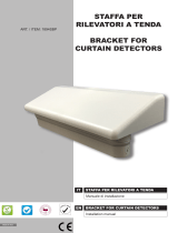
3. REGOLAZIONE DELLA LENTE E CONFIGURAZIONE DIP-SWITCH E LOGICA LED
lamella di separazione
lente a tenda
supporto della lente
IT
MANUALE
INSTALLAZIONE
EN
INSTALLATION
MANUAL
Manuale installazione Sensore doppia tecnologia a tenda Art. DT01CW - Art. DT01CB
Installation manual Dual tech curtain intrusion detector Art. DT01CW - Art. DT01CB
Il sensore è dotato di un led esterno e di un led interno.
In caso di allarme della singola tecnologia si accende solo il led interno (breve flash per la microonda, accensione per 2 secondi per
l’infrarosso). A seguito di allarme della seconda tecnologia (allarme AND) si accende il led esterno per 4 secondi.
Le altre segnalazioni indicano la fase in cui si trova il sensore
- Lampeggio lento alternato led interno con esterno: fase di inizializzazione
- Breve flash led esterno: tempo di inibizione a seguito di un passaggio nel senso CONSENTITO quando è attiva la funzione di DIREZIONE (DIP 4 ON).
- Lampeggio rapido led esterno: ultimi 10 secondi del tempo di inibizione (DIP4 ON).
Il sensore è stato progettato per essere installato a protezione di varchi, ad esempio tra finestra e persiana e/o tapparella, oppure per proteggere
porte e portoni. Visto l’elevato angolo di copertura, è possibile installarlo in diverse modalità, dall’alto verso il basso oppure su un lato (vedi figura).

2
IT
DIP-SWITCH OFF ON
DIP 1 LED disabilitato LED abilitato
DIP 2 1 impulso di allarme doppio impulso per allarme
DIP 3 Portata a 2mt Portata 3.5mt
DIP 4 direzione allarme disabilitata direzione allarme abilitata
DIP 5 direzione da1 --> 2 allarme direzione 2 --> 1 allarme
+
+
TOP VIEW SIDE VIEWFRESNEL LENSPLASTIC ADAPTER
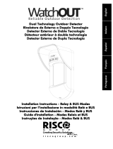
4. INSTALLAZIONE E COLLEGAMENTO
Scegliere la posizione adatta alle proprie esigenze, fissare il sensore utilizzando le torrette a strappo per ottenere la protezione Tamper. Il cavo può
passare dal forellino vicino ai terminali, oppure se la sezione è molto grossa è possibile passare dallo sfondabile (vedi figura sotto), una volta termi-
nato il montaggio chiudere e serrare il sensore con la vite in dotazione.
torrette per la protezione antistrappo
foro passaggio cavi
sfondabile passaggio
cavi alternativo
2
1
5
4
3
2
1
foro per bloccaggio a vite

3
IT
Fissata la base posteriore fare scorrere il cavo nei fori scelti, fissare la scheda nella propria sede ad incastro e fissare i cavi negli ap-
positi terminali, chiudere la cover superiore e bloccare il tutto con la vite in dotazione (fig.)
Nella figura a fine manuale è possibile vedere diversi tipi di installazione, in centro alla finestra oppure su un lato, la possibilità di mon-
taggio sul lato è data dall’elevata apertura angolare della lente.
Si noti che i disegni sono puramente indicativi, pertanto si consiglia di testare sempre la copertura del sensore.
Durante la prima accensione il sensore necessita di un warm up, un tempo di attivazione per andare a regime, tale tempo è di circa
40’’. Meno violazioni si avranno durante questo tempo è più veloce sarà entrata in modalità operativa.
Il WARM UP è rappresentato dall’accensione alternata dei led interno ed esterno.
Una volta terminato tale tempo è possibile effettuare i test di portata necessari.
5. PRIMA ACCENSIONE E FUNZIONAMENTO
TAMPER: LINEA TAMPER ANTIAPERTURA - 400mA 40Vdc
ALARM: CONTATTO DI ALLARME 100 mA - 40 V - 16 Ω
SUPPLY: TERMINALI DI ALIMETAZIONE 13.8Vcc 26mA Max
5 4 3 2 1

4
EN
separation blade
curtain lens
support of the lens
The sensor is equipped with external and internal LED.
In case of alarm from one technology will only turn on the LED internal (short flash for the microwave, turning on for 2 seconds to PIR).
When PIR and MW go in alarm (AND alarm) the external led turn ON for 4 seconds.
Other reports:
- Slow flashing alternating internal and external LED: the initialization phase
- Short flash external LED: inhibition time, result of PERMITTED passage with DIRECTION function ON (DIP 4 ON).
- Rapid blinking of ext.LED: the last 10 seconds of the inhibition time (DIP4 ON).
1. INTRODUCTION
Art. DT01CW - Art. DT01CB is a dual technology curtain sensor, PIR and MW. It used for doors and windows protection. It has an
adjustable range from 2mt to 3.5mt. And is equipped with a system for the recognition the direction of alarm. The lens used in the
infrared has the ability to be rotated horizontally so you can install the sensor in 2 diffrenti guidelines (vertical and horizontal)
2. DESCRIPTION OF THE FUNCTION: DIRECTION ALARM
The sensor is able to detect the direction of movement so as to trig in alarm only when the passage is made in a given sense.
Activation is done by DIP4 ON. (with DIP4 OFF, the sensor triggers an alarm in both directions) The selection of the sense of alarm is
handled through the DIP5. This function is intended for applications where the sensor is installed on the windows and / or doors often
open, and there is continuous passage on the inner side.
The passage in NOT PERMITTED direction, generates immediate alarm signaling with LED lights outside.
The passage in PERMITTED direction generates the activation of the inhibition time of 2 minutes, with the relative signal by short flash
of the LED every 2 seconds. During this time period (2 minutes) there any violation of the sensor will not generate alarm.
During the last 10 seconds of the period of inhibition, the LED will begin to flash rapidly to indicate that the sensor will return in the
operating status and will be able to generate alarm.
Example: If the sensor is installed on access to a terrace, it is possible come and go for 2 minutes without generating an alarm.
After this time, the sensor will be operative, giving alarm in the programmed direction.
The sensor is designed to be installed to protect the openings, for example between the window and the shutter, or to doors and gates.
Due to the high angle of coverage and the ability to rotate the lens on the support of the pyroelectric, you can install it in different ways,
from top to bottom or on one side.
3. LENS AND DIP-SWITCH SETUP - LED INDICATION

5
EN
DIP-SWITCH OFF ON
DIP 1 LED disable LED enable
DIP 2 1 pulse for alarm 2 pulse for alarm
DIP 3 2mt coverage 3.5mt coverage
DIP 4 alarm from all direction Alarm from one direction*
DIP 5 1 --> 2 alarm 2 --> 1 alarm
*To use the directional system optimally, you need to be inserted into the lens on the pyroelectric element separator (see figure)
and install it paying attention to the direction selection (dip-swtch5).
4. INSTALLATION AND CONNECTION
Choose a suitable location, mount the sensor using the turrets tear to get the tamper protection.
The cable can go from a tiny hole next to the terminals, or if the section is very large, you can switch from the knock-out (see figure
below).
turrets for tamper protection
cable entry hole
knock-out cable passage
1
2
1
2
1
2
+
+
TOP VIEW SIDE VIEWFRESNEL LENSPLASTIC ADAPTER
2
1
1
2
3
4
5
housing screw

6
EN
Fixed base rear slide the cable through the holes selected, secure the board in its housing interlocking and fix the cables into the
appropriate terminals. Use the scew to fix the top.
In the figure at the end of manual, you can see different types of installation, in the center of the window or on a side. The drawings
are for guidance only, so you should always test the sensor.
At start up the sensor needs a warm up time, this time is about 40’’. There will be fewer violations during this time is the faster entry
into operational mode.
The WARM UP is represented from internal and external blink LEDs
Once you have finished this, you may perform the tests necessary air flow.
5. WARM UP AND OPERATION
TAMPER: TAMPER ANTIOPENING LINE - 400mA 40Vdc
ALARM: ALARM CONTACT 100 mA - 40 V - 16 Ω
SUPPLY: 13.8Vcc 26mA Max
1 2 3 4 5

90°
120cm
20cm
FRONT VIEW SIDE VIEW
90°
120cm
20cm
FRONT VIEW SIDE VIEW

Alimentazione / Input Voltage 10 to 15 Vdc
Consumo / Current Drain (Alarm/Stand-By) (18 mA / 26mA) @ 13.8 Vdc
Portata in lunghezza / Coverage 2 - 3,5 m
Portata in larghezza / Angle 165°
Piroelettrico / PIR 2 elementi / 2 elements
Microonda classe ricevitore / microwave receiver class 2
Lente (fasci e livelli) / Lens (beams and levels) 6 beams on 1 levels
Durata allarme / Alarm period 4 sec.
Antiapertura / Anti-opening
✔
Contatto di allarme / Alarm’s Contact 100 mA - 40 V - 16 Ω
Contatto di tamper / Tamper Switch Max 400 mA - 40 Vdc
Temperatura di esercizio / Operating Temperature From -25 °C to +55 °C
RFI Protezione / Protection 10 V / m (20 /1000 MHz)
Led WALK TEST (MW and PIR)
✔
Cover / Housing ABS
Dimensioni / Dimensions L145 x H37 x P30 mm
SPECIFICHE TECNICHE / SPECIFICATIONS
Installation must be carried out following the local installation norms by qualified personnel.
The manufacturer refuses any responsibility when changes or unauthorized repairs are made to the product/system.
It is recommended to test the operation of the alarm product/system at least once a month. Despite frequent testing and
due to, but not limited to, any or all of the following: tampering, electrical or communication disruption or improper use, it
is possible for the product/system to fail to prevent burglary, rubbery, fire or otherwise. A properly installed and maintained
alarm system can only reduce the risk that this happens.
L’installazione deve essere eseguita a regola d’arte da personale specializzato.Il costruttore declina ogni responsabilità
nel caso in cui il prodotto venga manomesso da persone non autorizzate. Si raccomanda di verificare il corretto funzio-
namento del sistema d’allarme almeno una volta al mese, tuttavia un sistema di allarme elettronico affidabile non evita
intrusioni, rapine, incendi o altro, ma si limita a diminuire il rischio che tali situazioni si verifichino.
www.comelitgroup.com
Passion.Technology.Design.
1/8