
Инжектор питания VE44PB 4-Output POH/POE
A
Обзор оборудования
Вид спереди
1
Индикаторы состояния выхода
2
Индикатор питания
Вид сзади
1
Терминал заземления
2
Входные разъемы
3
Разъем питания
4
Переключатель питания
5
Выходные разъемы
Установка оборудования
1
Выполните заземление VE44PB. Для этого подсоедините терминал
заземления на устройстве к надежно заземленному объекту с
помощью заземляющего провода.
Примечание: Не пропускайте это действие. Надлежащее
заземление помогает предотвратить повреждение
устройства из-за перепадов напряжения или
разрядов статического электричества.
2
Подключите источник питания переменного тока к VE44PB с
помощью шнура питания.
3
Руководствуясь схемой установки, подключите PoH-совместимый
приемник (PD) к выходному разъему 1 с помощью кабеля Ethernet.
VE1812R и VE802R используются в качестве примера.
Примечание: Для других типов применения обратитесь к
руководству пользователя.
4
Подключите передатчик к входному разъему 1. В
проиллюстрированном примере VE44PB добавляет PoH в сигнал
HDBaseT, поступающий от VS1818T, для питания подключенных
приемников. Повторите шаги 3 и 4, чтобы подключить
дополнительные передатчики и приемники.
ВАЖНО:
Для сквозной передачи сигналов обязательно подключите
передатчик и приемник к одной паре входного и выходного разъема
(например, входной разъем 2 и выходной разъем 2).
5
Включите выключатель питания.
6
Включите питание устройств, подключенных к входным разъемам.
B
Установка оборудования
Крепление кронштейна
1
Открутите винты со стороны, показанной на схеме выше.
2
Используйте винты из шага 1, чтобы закрепить монтажный
кронштейн в нижней части передатчика.
Монтаж в стойке
Привинтите монтажный кронштейн к стойке в любом удобном месте.
Примечание: Данные винты не прилагаются в комплекте.
Рекомендуется использовать утопленные винты с
крестообразным шлицем M5 x 12 Philips типа I.
Монтаж на стене
Используйте центральное отверстие, чтобы прикрепить кронштейн к
стене.
Iniettore di potenza POH/POE a 4 uscite VE44PB
www.aten.com
A
Revisione Hardware
Vista anteriore
1
LED di stato delle uscite
2
LED accensione
Vista posteriore
1
Terminale di messa a terra
2
Connettori di entrata
3
Presa per l’alimentazione
4
Interruttore di accensione
5
Connettori di uscita
Installazione Hardware
1
Collega a terra il VE44PB collegando un capo del cavo di messa a terra al
terminale della terra, e l’altro capo a un oggetto adatto, collegato alla terra.
Nota: Non saltare questo passaggio. Una corretta messa a terra aiuta
a evitare danni all’unità causati da sbalzi di tensione o elettricità
statica.
2
Alimenta il VE44PB con corrente alternata usando il cavo di alimentazione.
3
Come mostrato nel diagramma di installazione, collega un ricevitore
compatibile PoH (PD) al connettore di uscita 1 usando un cavo Ethernet. Il
VE1812R e il VE802R sono usati come esempi.
Nota: Per altri tipi di applicazione, vedi il manuale utente.
4
Collega un trasmettitore al connettore di entrata 1. Nell’esempio mostrato,
il VE44PB aggiunge PoH al segnale HDBaseT che arriva dal VS1818T
per alimentare i ricevitori collegati. Ripeti i punti 3 e 4 per collegare altri
trasmettitori e ricevitori.
IMPORTANTE:
Perché il segnale passi, assicurati di aver connesso il trasmettitore e il
ricevitore alle stesse coppie di connettori di entrata e di uscita (per esempio,
il connettore di entrata 2 con il connettore di uscita 2).
5
Accendi l’interruttore.
6
Accendi i dispositivi collegati ai connettori di entrata.
B
Installazione Hardware
Attaccare la staffa
1
Svita le viti dal lato, come si vede nel diagramma qua sopra.
2
Usa le viti del punto 1 per fi ssare la staffa di montaggio sul fondo del
trasmettitore.
Montaggio in rack
Fissare la staffa nella posizione più comoda del rack.
Nota: Queste viti non vengono fornite nella confezione. Consigliamo di usare
viti a stella incassate Philips M5 x 12 di tipo I.
Montaggio a parete
Usa il foro centrale per fi ssare la staffa su una superfi cie stabile.
VE44PB Inyector de alimentación POE/POH de 4 salidas
www.aten.com
A
Revisión del hardware
Vista frontal
1
LED de estado de salida
2
LED de alimentación
Vista posterior
1
Terminal de conexión a tierra
2
Conectores de entrada
3
Toma de corriente
4
Botón de encendido
5
Conectores de salida
Instalación del hardware
1
Conecte a tierra el VE44PB conectando un extremo de un cable de
conexión a tierra al terminal de conexión a tierra y el otro extremo a un
objeto correctamente conectado a tierra.
Nota: No omita este paso. Una conexión a tierra adecuada ayuda a evitar
que se produzcan daños en la unidad por picos de tensión o por
electricidad estática.
2
Alimente al VE44PB con energía de CA utilizando el cable de alimentación.
3
Según el diagrama de instalación, conecte un receptor compatible con PoH
(PD) al conector de salida 1 mediante un cable Ethernet. Los VE1812R y
VE802R se utilizan como ejemplo.
Nota: Para otros tipos de aplicaciones, consulte el manual del usuario.
4
Conecte un transmisor al conector de entrada 1. En el ejemplo ilustrado,
el VE44PB añade PoH a la señal HDBaseT proveniente del VS1818T para
encender los receptores conectados. Repita los pasos 3 y 4 para conectar
más transmisores y receptores.
IMPORTANTE:
Para que pasen las señales, asegúrese de conectar el transmisor y el
receptor a los mismos pares de conectores de entrada y salida (p. ej.,
conector de entrada 2 y conector de salida 2).
5
Encienda el botón de encendido.
6
Encienda los dispositivos conectados a los conectores de entrada.
B
Instalación del hardware
Fijación del soporte
1
Desatornille los tornillos del lado que se muestra en el diagrama de arriba.
2
Utilice los tornillos del paso 1 para atornillar el soporte de montaje en la
parte inferior del transmisor.
Montaje en rack
Atornille el soporte en cualquier lugar conveniente en el bastidor.
Nota: No se proveen estos tornillos. Recomendamos que utilice tornillos Philips
tipo I M5 x 12 de estrella, empotrados.
Montaje en pared
Use el orifi cio central para atornillar el soporte en una superfi cie de pared
segura.
VE44PB POH/POE Strominjektor mit 4 Ausgängen
www.aten.com
A
Hardware Übersicht
Ansicht von vorne
1
Ausgang Status LEDs
2
Netz-LED
Ansicht von hinten
1
Erdungsanschluss
2
Eingangsanschlüsse
3
Netzbuchse
4
Netzschalter
5
Ausgangsanschlüsse
Wandmontage
Verwenden Sie die mittlere Öffnung, um die Halterung an eine sichere
Wandfl äche zu schrauben.
Hardware Installation
1
Erden Sie den VE44PB, indem Sie ein Ende eines Erdungskabels mit dem
Erdungsanschluss und das andere Ende mit einem geeigneten geerdeten
Gegenstand verbinden.
Hinweis: Lassen Sie diesen Schritt nicht aus. Eine angemessene
Erdung hilft bei der Verhinderung von Geräteschäden durch
Spannungsspitzen oder statische Elektrizität.
2
Versorgen Sie den VE44PB über das Netzkabel mit Wechselstrom.
3
Schließen Sie anhand des Installationsdiagramms einen PoH-kompatiblen
Empfänger (PD) mit einem Ethernetkabel an den Ausgangsanschluss 1 an.
Als Beispiel werden der VE1812R und der VE802R verwendet.
Hinweis: Für andere Arten von Anwendungen lesen Sie bitte das
Benutzerhandbuch.
4
Schließen Sie einen Sender an den Eingangsanschluss 1 an. In dem
abgebildeten Beispiel fügt der VE44PB dem vom VS1818T kommenden
HDBaseT Signal PoH hinzu, um die angeschlossenen Empfänger
einzuschalten. Wiederholen Sie Schritt 3 und 4, um weitere Sender und
Empfänger anzuschließen.
WICHTIG:
Damit die Signale durchlaufen können, müssen Sender und Empfänger
an die gleichen Eingangs- und Ausgangsanschlusspaare angeschlossen
werden (z.B. Eingangsanschluss 2 und Ausgangsanschluss 2).
5
Schalten Sie den Netzschalter ein.
6
Schalten Sie die an den Eingangsanschlüssen angeschlossenen Geräte ein.
B
Hardware Installation
Anbringen der Halterung
1
Lösen Sie die Schrauben von der Seite, die in der obigen Abbildung
dargestellt ist.
2
Verwenden Sie die Schrauben aus Schritt 1, um die Montagehalterung an
der Unterseite des Senders anzuschrauben.
Rack-Montage
Befestigen Sie die Halterung mittels Schrauben an einer geeigneten Stelle im
Rack.
Hinweis: Diese Schrauben sind nicht im Lieferumfang enthalten.
Wir empfehlen die Verwendung von M5 x 12 Philips Typ I
Kreuzschlitzschrauben mit Vertiefung.
Injecteur électrique POH/POE 4-sorties VE44PB
www.aten.com
A
Présentation du matériel
Vue de devant
1
LEDs d’état de sortie
2
LED d'alimentation
Vue de derrière
1
Prise de terre
2
Connecteurs d’entrée
3
Prise d'alimentation
4
Bouton marche/arrêt
5
Connecteurs de sortie
Installation matérielle
1
Mettez à terre le VE44PB en connectant une extrémité d’un câble de terre au
terminal de terre et l’autre extrémité à un objet convenablement relié à terre.
Remarque : N'ignorez pas cette étape. Une mise à terre correcte évite tout
dommage à l’unité depuis des surtensions ou de l’électricité
statique.
2
Alimentez le VE44PB avec de l’électricité CA en utilisant le cordon
d’alimentation.
3
En vous référant au diagramme d’installation, connectez un récepteur
compatible PoH (PD) au Connecteur de Sortie 1 en utilisant un câble
Ethernet. Le VE1812R et VE802R sont utilisés comme exemples.
Remarque : Pour d’autres types d’applications, veuillez consulter le mode
d’emploi.
4
Connectez un transmetteur au Connecteur d’Entrée 1. Dans l’exemple
illustré, le VE44PB ajoute PoH dans le signal HDBaseT venant du VS1818T
pour alimenter les récepteurs connectés. Répétez l’étape 3 et 4 pour
connecter encore plus de transmetteurs et de récepteurs.
IMPORTANT:
Pour permettre aux signaux de passer, assurez-vous de bien connecter le
transmetteur et le récepteur sur les mêmes paires de Connecteur d’Entrée
et de Sortie (comme Connecteur d’Entrée 2 et Connecteur de Sortie 2).
5
Mettez en position de marche le commutateur électrique.
6
Mettez en position de marche tous les appareils connectés aux Connecteurs
d’Entrée.
B
Installation matérielle
Assembler le bras
1
Dévissez les vis depuis le côté comme indiqué dans le diagramme ci-dessus.
2
Utilisez les vis de l’étape 1 pour assembler le bras sur le bas du
Transmetteur.
Montage en rack
Vissez le support dans un quelconque emplacement pratique sur le rack.
Remarque : Ces vis ne sont pas fournies. Nous vous recommandons d’utiliser
des vis à tête avec croix type I, M5 x 12 Philips.
Montage mural
Utilisez le trou central pour visser le bras sur une surface murale sécurisée.
© Copyright 2020 ATEN
®
International Co., Ltd.
ATEN and the ATEN logo are trademarks of ATEN International Co., Ltd. All rights reserved. All
other trademarks are the property of their respective owners.
Part No. PAPE-1223-T10G Printing Date: 01/2020
4-Output POH/POE Power Injector
Quick Start Guide
VE44PB
VE44PB 4-Output POH/POE Power Injector
www.aten.com
ATEN VanCryst
™
B
Package Contents
1 4-Output POH/POE Power Injector
1 Mounting Kit
1 Power Cord Cable
1 User Instructions
Hardware Installation
A
Hardware Review
A
Hardware Review
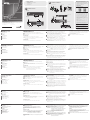
Front View
1
Output Status LEDs
2
Power LED
Rear View
1
Grounding Terminal
2
Input Connectors
3
Power Socket
4
Power Switch
5
Output Connectors
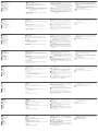
Hardware Installation
1
Ground the VE44PB by connecting one end of a grounding wire to the
grounding terminal and the other end to a suitable grounded object.
Note: Do not omit this step. Proper grounding helps to prevent damage to
the unit from power surges or static electricity.
2
Supply the VE44PB with AC power using the Power Cord.
3
Based on the installation diagram, connect a PoH compatible receiver (PD)
to the Output Connector 1 using an Ethernet cable. The VE1812R and
VE802R are used as an example.
Note: For other types of applications, refer to the user manual.
4
Connect a transmitter to Input Connector 1. In the illustrated example,
the VE44PB adds PoH into HDBaseT signal coming from the VS1818T to
power on the connected receivers. Repeat step 3 and 4 to connect more
transmitters and receivers.
IMPORTANT:
For the signals to pass through, make sure to connect the transmitter and
the receiver to the same Input and Output Connector pairs (e.g. Input
Connector 2 and Output Connector 2).
5
Turn on the Power Switch.
6
Power on the devices connected to the Input Connectors.
B
Hardware Installation
Attaching the Bracket
1
Unscrew the screws from the side shown in the diagram above.
2
Use the screws from step 1 to screw the mounting bracket on the bottom
of the Transmitter.
Rack Mounting
Screw the bracket into any convenient location on the rack.
Note: These screws are not provided. We recommend that you use M5 x 12
Philips Type I cross, recessed type screws.
Wall Mounting
Use the center hole to screw the bracket onto a secure wall surface.
www.aten.com
4
1
1
2
2
3
5
Front View
Rear View
2
1
Rack Mounting Wall Mounting
M3 x 5
Attaching the Bracket
M3 x 5
1
4
Example: VE802R Example: VE1812R
Power Switch
Power Cord
Example: VS1818T
Transmitter
Receiver
VE44PB (Rear)
2
3
5
이 기기는 업무용(A급) 전자파적합기기로서 판매자 또는 사용자는 이 점을
주의하시기 바라며, 가정외의 지역에서 사용하는 것을 목적으로 합니다.
EMC Information
FEDERAL COMMUNICATIONS COMMISSION INTERFERENCE
STATEMENT:
This equipment has been tested and found to comply with the limits
for a Class A digital device, pursuant to Part 15 of the FCC Rules.
These limits are designed to provide reasonable protection against
harmful interference when the equipment is operated in a commercial
environment. This equipment generates, uses, and can radiate radio
frequency energy and, if not installed and used in accordance with
the instruction manual, may cause harmful interference to radio
communications. Operation of this equipment in a residential area
is likely to cause harmful interference in which case the user will be
required to correct the interference at his own expense.
FCC Caution: Any changes or modifi cations not expressly approved by
the party responsible for compliance could void the user's authority to
operate this equipment.
Warning: Operation of this equipment in a residential environment
could cause radio interference.
Suggestion: Shielded twisted pair (STP) cables must be used with the
unit to ensure compliance with FCC & CE standards.
This device complies with Part 15 of the FCC Rules. Operation is subject
to the following two conditions:(1) this device mat not cause harmful
interference, and(2) this device must accept any interference received,
including interference that may cause undesired operation.
Important. Before proceeding, download the Installation and
Operation Manual by visiting the website, www.aten.com and
navigating to the product page. The manual includes important
warnings, loading specifi cations and grounding instructions.
Achtung: Der Gebrauch dieses Geräts in Wohnumgebung kann
Funkstörungen verursachen.
S
upport and Documentation Notice
All information, documentation, fi rmware, software utilities,
and specifi cations contained in this package are subject to
change without prior notifi cation by the manufacturer.
To reduce the environmental impact of our products, ATEN
documentation and software can be found online at
http://www.aten.com/download/
Technical Support
www.aten.com/support
Scan for more information
ATEN Website User Manual
La pagina si sta caricando...
-
 1
1
-
 2
2


in altre lingue
- English: ATEN VE44PB Quick start guide
- français: ATEN VE44PB Guide de démarrage rapide
- español: ATEN VE44PB Guía de inicio rápido
- Deutsch: ATEN VE44PB Schnellstartanleitung
- русский: ATEN VE44PB Инструкция по началу работы
- português: ATEN VE44PB Guia rápido
- polski: ATEN VE44PB Skrócona instrukcja obsługi
- 日本語: ATEN VE44PB クイックスタートガイド
- Türkçe: ATEN VE44PB Hızlı başlangıç Kılavuzu
Documenti correlati
-
ATEN VE2812AEUT Guida Rapida
-
ATEN VE2812AUST Guida Rapida
-
ATEN VE3912T Guida Rapida
-
ATEN VE1801AEUT Guida Rapida
-
ATEN VE2812AT Guida Rapida
-
ATEN VE1901AEUT DisplayPort HDBaseT-Lite Transmitter Guida utente
-
-
-
ATEN VP1421 Guida Rapida
-
ATEN VE802 Guida Rapida