
이 기기는 업무용(A급) 전자파적합기기로서 판매자 또는 사용자는 이 점을
주의하시기 바라며, 가정외의 지역에서 사용하는 것을 목적으로 합니다.
Scan for
more information
EMC Information
FEDERAL COMMUNICATIONS COMMISSION INTERFERENCE
STATEMENT:
This equipment has been tested and found to comply with the limits
for a Class A digital device, pursuant to Part 15 of the FCC Rules.
These limits are designed to provide reasonable protection against
harmful interference when the equipment is operated in a commercial
environment. This equipment generates, uses, and can radiate radio
frequency energy and, if not installed and used in accordance with
the instruction manual, may cause harmful interference to radio
communications. Operation of this equipment in a residential area
is likely to cause harmful interference in which case the user will be
required to correct the interference at his own expense.
FCC Caution: Any changes or modifi cations not expressly approved by
the party responsible for compliance could void the user's authority to
operate this equipment.
Warning: Operation of this equipment in a residential environment
could cause radio interference.
Suggestion: Shielded twisted pair (STP) cables must be used with the
unit to ensure compliance with FCC & CE standards.
This device complies with Part 15 of the FCC Rules. Operation is subject
to the following two conditions:(1) this device mat not cause harmful
interference, and(2) this device must accept any interference received,
including interference that may cause undesired operation.
Important. Before proceeding, download the Installation and
Operation Manual by visiting the website, www.aten.com and
navigating to the product page. The manual includes important
warnings, loading specifi cations and grounding instructions.
Achtung: Der Gebrauch dieses Geräts in Wohnumgebung kann
Funkstörungen verursachen.
S
upport and Documentation Notice
All information, documentation, fi rmware, software utilities,
and specifi cations contained in this package are subject to
change without prior notifi cation by the manufacturer.
To reduce the environmental impact of our products, ATEN
documentation and software can be found online at
http://www.aten.com/download/
Technical Support
www.aten.com/support
Power Supply Information
A
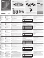
Hardware Review
Top View
1
IR Port
2
HDMI Input Port
3
Audio Input Port
4
VGA Input Port
5
Source Switch Pushbutton
System Status LEDs
6
Link LED
7
Power LED
Source Input Status LEDs
8
HDMI LED
9
AUTO LED
10
VGA LED
Step 2 Secure the unit to the installation site using 4 screws.
Note: Screws are not included in the package contents.
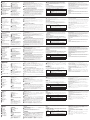
Power Supply Information
1
Cut the connector end of the power adapter.
2
Strip 5 mm (0.5 cm) off the insulation cover of the Power Adapter cable to expose two
wires: a +5V wire and a GND (grounding) wire.
3
Insert the exposed +5V wire and GND (grounding) wire tightly into the provided 2-pin
Terminal Block Connector.
Note: One method to determine an exposed wire’s polarity (i.e., +5V or GND) is by using
a voltmeter.
C
Hardware Installation
1
Connect the HDMI / VGA Input Port on the VE2812AEUT to the HDMI / VGA Output
port on your video source device using an HDMI / VGA cable. For a VGA source, also
connect the Audio Output port of the source device to the Audio Input Port on the
VE2812AEUT.
2
With the built-in PoH PD capability, the VE2812AEUT can be powered on through an
Ethernet cable. Connect one end of a Cat5e/6/6a cable to the HDBaseT Output port
on the transmitter, and then connect the other end to the HDBaseT Input port on the
receiver.
3
(Optional) Connect the RS-232 control interface of your computer or control
system
to the RS-232 Serial Port on the VE2812AEUT.
4
(Optional) Connect an IR transmitter / receiver to the IR Port on the VE2812AEUT.
5
Please follow the instructions described in Power Supply Information.
(Optional) Plug the Power Adapter cable into the Power Terminal Block on the
VE2812AEUT to power on the device.
Note:
The VE2812AEUT prioritizes the power supply from the power adapter when
the Power Adapter is plugged in.
Operation
Source Input Operation
The VE2812AEUT can be used as a switch by connecting two source devices to the
transmitter. Press the Source Switch Pushbutton on the VE2812AEUT to switch
between different input modes – Auto, HDMI, and VGA mode. Refer to the table
below for details.
Input Mode Description
Auto (Default)
•
Before power on, the VE2812AEUT prioritizes HDMI transmission
if both HDMI Input and VGA Input ports are connected.
•
After powered on, the VE2812AEUT prioritizes the latest
detected input source transmission to the connected receiver.
HDMI The VE2812AEUT only transmits the HDMI source to the
connected receiver.
VGA The VE2812AEUT only transmits the VGA source and its audio
input to the connected receiver.
In addition, the source input can be remotely selected by RS-232 command. Please refer
to the VE2812AEUT user manual for further details.
RS-232 Channel Transmission
You can connect an RS-232 serial device to the VE2812AEUT RS-232 Serial Port, such
as a touchscreen and bar code scanner. The RS-232 signal transmission fl ow is shown in
the following example: From a source device, the RS-232 signal is transmitted (Tx) to the
receiving (Rx) unit; the VE2812AEUT transmits (Tx) signals to the display device (Rx).
Working in Long Reach Mode
The VE2812AEUT supports long reach mode. When this mode is applied, the maximum
range can be enhanced to 150 meters at resolutions up to 1080p. Please refer to the
VE2812AEUT user manual for further details.
Compatible Products
Receivers
The VE2812AEUT is compatible with the VE2812R , VE1812R, VE811R, VE812R,
VE814AR, VE801R, VE802R, VE601R, VP1421, or future ATEN HDBaseT Receivers.
POH PSE
The VE2812AEUT is compatible with VE44PB, VP1421, or future ATEN PoH PSE products,
which can power the VE2812AEUT.
© Copyright 2019 ATEN
®
International Co., Ltd.
ATEN and the ATEN logo are trademarks of ATEN International Co., Ltd. All rights reserved.
All other trademarks are the property of their respective owners.
Part No. PAPE-1223-M91G Printing Date: 12/2019
HDMI & VGA HDBaseT Transmitter
with EU Wall Plate / POH
Quick Start Guide
VE2812AEUT
VE2812AEUT HDMI & VGA HDBaseT Transmitter with EU Wall Plate / POH
www.aten.com
ATEN VanCryst
™
Package Contents
1 x VE2812AEUT HDMI & VGA HDBaseT Transmitter with EU Wall Plate / POH
1 x 3 Pin RS-232 Terminal Block
1 x 2 Pin Power Terminal Block
1 x Mounting Kit
1 x Power Adapter
1 x User Instructions
C
Hardware Installation
5
4
3
2
1
1
6
3
7
2
5
4
8
9
10
Top View
Side Panel View 1 Side Panel View 2
NO
+5V
GND
GND
5mm
1
2
3
(+)
(-)
+5V
Power Supply Information
4
1
1
Top View Side View
Example: VE2812R Receiver
2
3
5
1
Installation
Wall Mouting
B
A
Hardware Review
Side Panel View 1 & 2
1
Firmware Upgrade Switch
2
HDBaseT Long Reach Mode Switch
3
Power Terminal Block
4
RS-232 Port
5
HDBaseT Out Port
Troubleshooting
The Firmware Upgrade Switch is reserved
for technical support. If you would like to
do a fi rmware upgrade yourself, please
contact ATEN technical support.
B
Installation
Wall Mounting
Step 1 Secure the supplied frame to your
installation site using 4 screws (EU type) or 2
screws (MK type). This installation site can be a
wall or ceiling.
STEP 1
STEP 2
For MK Type
STEP 1
STEP 2
For EU Type
Émetteur HDBaseT HDMI et VGA VE2812AEUT avec plaque murale UE / POH
www.aten.com
VE2812AEUT HDMI und VGA HDBaseT Sender mit EU-Wandplatte / POH
www.aten.com
Transmisor HDBaseT HDMI y VGA VE2812AEUT con placa de pared UE / POH
www.aten.com
VE2812AEUT Передатчик HDBaseT HDMI и VGA (EU - исполнение для Европейского союза) / POH
www.aten.com
Trasmettitore HDMI e VGA HDBaseT VE2812AEUT con piastra da parete UE / POH
www.aten.com
A
Description de l’appareil
Vue de dessus
1
Port IR
2
Port d'entrée HDMI
3
Port d'entrée audio
4
Port d'entrée VGA
5
Bouton-poussoir de commutation
de source
Diodes d'état du système
6
Diode de lien
7
Voyant d’alimentation
Diodes d'état de l'entrée source
8
LED HDMI
9
LED auto
10
LED VGA
Vue des panneaux latéraux 1 et 2
1
Commutateur de mise à niveau
du microprogramme
Étape 2 Fixez l'unité au site d'installation à l'aide de 4 vis.
Remarque : Les vis ne sont pas incluses dans le contenu de l'emballage.
Informations relatives à l’alimentation
1
Coupez l’extrémité du connecteur de l’adaptateur secteur.
2
Dénudez 5 mm (0,5 cm) de gaine isolante sur le câble de l’adaptateur secteur pour
mettre à nu deux fi ls : un fi l +5V et un fi l GND (masse).
3
Insérez le fi l +5V et le fi l GND dénudés dans le connecteur bornier à 2 broches fourni.
Remarque : Une méthode pour déterminer la polarité d'un fi l exposé (c.-à-d., +5V ou
GND) consiste à utiliser un voltmètre.
C
Installation matérielle
1
Connectez le Port d’entrée HDMI/VGA du VE2812AEUT au Port de sortie HDMI/VGA
de votre périphérique source vidéo à l’aide d’un câble HDMI/VGA. Pour une source
VGA, connectez également le Port de sortie audio du périphérique source au Port
d'entrée audio du VE2812AEUT.
2
Grâce à la capacité PoH PD intégrée, le VE2812AEUT peut être alimenté via un câble
Ethernet. Connectez une extrémité d'un câble Cat5e/6/6a au Port de sortie HDBaseT
de l'émetteur, puis connectez l'autre extrémité au Port d'entrée HDBaseT du récepteur.
3
(Optionnel) Connectez l’interface de contrôle RS-232 de votre ordinateur ou
système
de contrôle au Port série RS-232 du VE2812AEUT.
4
(Optionnel) Raccordez un émetteur/récepteur IR au Port IR du VE2812AEUT.
5
Veuillez suivre les instructions décrites dans Informations relatives à l’alimentation.
(Optionnel) Branchez le câble de l'Adaptateur d'alimentation dans le Bornier
d'alimentation sur le VE2812AEUT pour mettre l'appareil sous tension.
Remarque :
Le VE2812AEUT donne la priorité à l’alimentation provenant de
l’adaptateur secteur si ce dernier est branché.
Fonctionnement
Fonctionnement de l’entrée source
Le VE2812AEUT peut être utilisé comme commutateur, en raccordant deux appareils
sources à l’émetteur. Appuyez sur le bouton poussoir du commutateur de
source du VE2812AEUT afi n de basculer entre les différents modes d’entrée – Mode
automatique, HDMI et VGA. Consultez le tableau ci-dessous pour des détails.
Mode d’entrée Description
Automatique
(par défaut)
•
Avant la mise sous tension, le VE2812AEUT donne la priorité
à la transmission HDMI si les ports d’entrée HDMI et VGA sont
connectés.
•
Après la mise sous tension, le VE2812AEUT donne la priorité
à la dernière transmission de source d'entrée détectée vers le
récepteur connecté.
HDMI Le VE2812AEUT transmet uniquement la source HDMI au
récepteur connecté.
VGA Le VE2812AEUT transmet uniquement la source VGA et son
entrée audio au récepteur connecté.
De plus, l'entrée source peut être sélectionnée à distance par commande RS-232. Veuillez
consulter le manuel de l'utilisateur du VE2812AEUT pour plus de détails.
Transmission de canal RS-232
Vous pouvez connecter un périphérique série RS-232 au port série RS-232 du
VE2812AEUT, tel qu’un écran tactile et un lecteur de codes à barres. Le fl ux de
transmission du signal RS-232 est présenté sur l’exemple suivant : Depuis un appareil
source, le signal RS-232 est transmis (Tx) vers le l'unité de réception (Rx); le VE2812AEUT
transmet (Tx) les signaux vers le dispositif d’affi chage (Rx).
Fonctionnement en mode longue portée
Le VE2812AEUT prend en charge le mode longue portée. Lorsque ce mode est appliqué,
la portée maximum peut être prolongée jusqu’à 150 mètres, à des résolutions jusque
1080p. Veuillez consulter le manuel de l'utilisateur du VE2812AEUT pour plus de détails.
Produits compatibles
Récepteurs
Le VE2812AEUT est compatible avec les récepteurs VE2812R, VE1812R, VE811R, VE812R,
VE814AR, VE801R, VE802R, VE601R, VP1421 ou futurs récepteurs ATEN HDBaseT.
POH PSE
Le VE2812AEUT est compatible avec les produits VE44PB, VP1421, ou les futurs produits
PoH PSE ATEN, capables d’alimenter le VE2812AEUT.
2
Commutateur de mode longue portée
HDBaseT
3
Connecteur bornier d'alimentation
4
Port RS-232
5
Ports de sortie HDBaseT
Dépannage
Le commutateur de mise à niveau du
microprogramme est réservé au support
technique. Si vous voulez faire une mise
à niveau du fi rmware vousmême, veuillez
contacter l’assistance technique ATEN.
B
Installation
Montage au mur
Étape 1 Fixez le cadre fourni sur votre site
d'installation à l'aide de 4 vis (type UE) ou 2 vis
(type MK). Ce site d'installation peut être un
mur ou un plafond.
A
Hardwareübersicht
Ansicht von oben
1
IR Anschluss
2
HDMI-Eingang
3
Audio-Eingang
4
VGA-Eingang
5
Quellenschalter Drucktaste
Systemstatus LEDs
6
Link LED
7
Betriebszustands-LED
Quelleneingang Status LEDs
8
HDMI-LED
9
Auto-LED
10
VGA-LED
Seitenwand Ansicht 1 & 2
1
Schalter für Firmware-
Aktualisierung
Schritt 2 Befestigen Sie das Gerät mit 4 Schrauben am Montageort.
Hinweis: Schrauben sind nicht im Lieferumfang enthalten.
Informationen zur Stromversorgung
1
Schneiden Sie das Anschlussende des Netzkabels ab.
2
Entfernen Sie 5 mm (0,5 cm) von der Isolierabdeckung des Netzteilkabels, sodass zwei
Drähte freiliegen: ein +5V-Draht und ein Erdungsdraht.
3
Stecken Sie den freigelegten +5V Draht und den Erdungsdraht fest in den 2-poligen
Anschluss am Anschlussblock.
Hinweis: Eine Methode zur Bestimmung der Polarität einer freiliegenden Leitung (z.B.
+5V oder GND) ist die Verwendung eines Voltmeters.
C
Installation der Hardware
1
Verbinden Sie den HDMI/VGA-Eingang des VE2812AEUT mit dem HDMI/VGA-Ausgang
Ihres Videoquellgeräts über ein HDMI/VGA-Kabel. Schließen Sie für eine VGA-Quelle
auch den Audioausgang des Quellgeräts an den Audioeingang des VE2812AEUT an.
2
Mit der integrierten PoH PD Funktion kann der VE2812AEUT über ein Ethernet-Kabel
eingeschaltet werden. Verbinden Sie ein Ende eines Cat5e/6/6a Kabels mit dem HDBaseT-
Ausgang am Sender und das andere Ende mit dem HDBaseT-Eingang am Empfänger.
3
(Optional) Verbinden Sie die RS-232 Schnittstelle Ihres Computers oder
Steuerungs
systems mit dem RS-232 serieller Anschluss des VE2812AEUT.
4
(Optional) Verbinden Sie einen IR-Sender/-Empfänger mit dem IR Anschluss am
VE2812AEUT.
5
Bitte folgen Sie den Anweisungen in den Informationen zur Stromversorgung.
(Optional) Stecken Sie das Netzteilkabel in den Stromanschlussblock des
VE2812AEUT, um das Gerät einzuschalten.
Hinweis:
Der VE2812AEUT bevorzugt die Stromversorgung über das Netzteil, wenn
das Netzteil eingesteckt ist.
Bedienung
Quelleneingang bedienen
Der VE2812AEUT kann durch Anschluss von zwei Eingangsgeräten an den Sender
als Switch verwendet werden. Drücken Sie die Taste für den Quellenwechsel am
VE2812AEUT, um zwischen den verschiedenen Eingangsmodi - Auto, HDMI und VGA
- zu wechseln. Einzelheiten entnehmen Sie bitte der folgenden Tabelle.
Eingangsmodus Beschreibung
Auto (Standard)
•
Vor dem Einschalten bevorzugt der VE2812AEUT die HDMI-
Übertragung, wenn sowohl der HDMI-Eingang als auch der
VGA-Eingang angeschlossen sind.
•
Nach dem Einschalten bevorzugt der VE2812AEUT die zuletzt
erkannte Eingangsquellenübertragung an den angeschlossenen
Empfänger.
HDMI Der VE2812AEUT sendet nur die HDMI-Quelle an den
angeschlossenen Empfänger.
VGA Der VE2812AEUT sendet nur die VGA-Quelle und ihren
Audioeingang an den angeschlossenen Empfänger.
Zusätzlich kann der Quelleingang per RS-232 Befehl ferngesteuert werden. Weitere
Einzelheiten entnehmen Sie bitte dem VE2812AEUT Benutzerhandbuch.
RS-232 Kanalübertragung
Sie können ein serielles RS-232 Gerät an den seriellen VE2812AEUT RS-232
Port anschließen, z.B. einen Touchscreen und Barcodescanner. Der RS-232
Signalübertragungsfl uss wird in folgendem Beispiel angezeigt: Von einem Eingangsgerät
wird das RS-232-Signal an das Empfangsgerät (Rx) übertragen (Tx); der VE2812AEUT
überträgt (Tx) Signale an das Anzeigegerät (Rx).
Im Lange Reichweite Modus arbeiten
Der VE2812AEUT unterstützt den Reichweite Modus. Wenn dieser Modus angewandt
wird, kann die maximale Reichweite auf 150 Meter erweitert werden, bei Aufl ösungen bis
1080p. Weitere Einzelheiten entnehmen Sie bitte dem VE2812AEUT Benutzerhandbuch.
Kompatible Produkte
Empfänger
Der VE2812AEUT ist kompatibel mit den VE2812R, VE1812R, VE811R, VE812R, VE814AR,
VE801R, VE802R, VE601R, VP1421 oder zukünftigen ATEN HDBaseT Empfängern.
POH PSE
Der VE2812AEUT ist kompatibel mit VE44PB, VP1421 oder zukünftigen ATEN PoH PSE Produkten,
die den VE2812AEUT mit Strom versorgen können.
2
HDBaseT Lange Reichweite Modus
Schalter
3
Stromanschlussblock
4
RS-232-Port
5
HDBaseT Ausgang
Problemlösung
Der Schalter für Firmware-Aktualisierung
ist für den technischen Support reserviert.
Wenn Sie die Firmware selbst aktualisieren
möchten, wenden Sie sich bitte an den
technischen Support von ATEN.
B
Installation
Wandmontage
Schritt 1 Befestigen Sie den mitgelieferten
Rahmen mit 4 Schrauben (Typ EU) oder 2
Schrauben (Typ MK) an Ihrem Montageort.
Dieser Montageort kann eine Wand oder
Decke sein.
A
Presentación del hardware
Vista superior
1
Puerto de infrarrojos
2
Puerto de entrada HDMI
3
Puerto de entrada de audio
4
Puerto de entrada VGA
5
Pulsador de cambio de fuente
Indicadores LED de estado
del sistema
6
LED de enlace
7
LED de alimentación
Indicadores LED de estado
de entrada de fuente
8
LED HDMI
9
LED Automático
10
LED VGA
Vista del panel lateral 1 y 2
1
Interruptor de actualización
de fi rmware
Nota: Los tornillos no se incluyen en el contenido de la caja.
Información sobre la fuente de alimentación
1
Corte el extremo del conector del adaptador de alimentación.
2
Quite 5 mm (0,5 cm) de la cubierta aislante del cable del adaptador de alimentación
para exponer dos cables: un cable +5V y un cable GND (tierra).
3
Inserte fi rmemente los cables expuestos de +5V y el cable GND (tierra) en el Conector
de bloque de terminales de 2 pines suministrado.
Nota: Puede utilizar un voltímetro para determinar la polaridad de un cable expuesto (es
decir, +5V o GND).
C
Instalación del hardware
1
Conecte el puerto de entrada HDMI/VGA del VE2812AEUT al puerto de salida HDMI/
VGA del dispositivo de fuente de vídeo con un cable HDMI/VGA. En el caso de una
fuente VGA, conecte también el puerto de salida de audio del dispositivo de fuente al
puerto de entrada de audio del VE2812AEUT.
2
Con la capacidad PoH PD integrada, el VE2812AEUT se puede encender a través de
un cable Ethernet. Conecte un extremo de un cable Cat5e/6/6a al puerto de salida
HDBaseT del transmisor y, a continuación, conecte el otro extremo al puerto de
entrada HDBaseT del receptor.
3
(Opcional) Conecte la interfaz de control RS-232 del ordenador o del
sistema de
control al puerto serie RS-232 del VE2812AEUT.
4
(Opcional) Conecte un transmisor/receptor IR al puerto IR del VE2812AEUT.
5
Siga las instrucciones indicadas en la Información sobre la fuente de
alimentación. (Opcional) Conecte el cable del adaptador de alimentación en
el bloque de terminales de alimentación del VE2812AEUT para suministrar
alimentación eléctrica al dispositivo.
Nota:
El VE2812AEUT da prioridad al suministro de alimentación del adaptador de
alimentación cuando el adaptador de alimentación esté conectado.
Funcionamiento
Operación de entrada de fuente
El VE2812AEUT se puede utilizar como conmutador, conectando dos dispositivos
fuente al transmisor. Presione el Pulsador de cambio de fuente del VE2812AEUT
para cambiar entre los distintos modos de entrada: Automático, HDMI y VGA.
Consulte la siguiente tabla para más información.
Modo de entrada Descripción
Automático
(predeterminado)
•
Antes del encendido, el VE2812AEUT da prioridad a la
transmisión HDMI si tanto los puertos de HDMI como los
puertos de entrada VGA están conectados.
•
Tras el encendido, el VE2812AEUT da prioridad a la última
transmisión de entrada detectada en el receptor conectado.
HDMI
El VE2812AEUT solo transmite la fuente HDMI al receptor conectado.
VGA El VE2812AEUT solo transmite la fuente VGA y su entrada de
audio al receptor conectado.
Además, el comando RS-232 puede seleccionar la entrada de fuente de forma remota.
Consulte el manual de usuario del VE2812AEUT para obtener más información.
Transmisión a través del canal RS-232
Puede conectar un dispositivo serie RS-232 al puerto serie RS-232 del VE2812AEUT, como,
por ejemplo, una pantalla táctil y un lector de códigos de barras. El fl ujo de transmisión de
la señal RS-232 se muestra en el siguiente ejemplo: Desde un dispositivo fuente, la señal
RS-232 se transmite (Tx) a la unidad receptora (Rx); el VE2812AEUT transmite (Tx) señales
al dispositivo de visualización (Rx).
Trabajar en modo de largo alcance
El VE2812AEUT admite el modo de largo alcance. Cuando se aplica este modo, el alcance
máximo se puede extender hasta 150 metros, con resoluciones de hasta 1080p. Consulte
el manual de usuario del VE2812AEUT para obtener más información.
Productos compatibles
Receptores
El VE2812AEUT es compatible con los dispositivos VE2812R, VE1812R, VE811R, VE812R,
VE814AR, VE801R, VE802R, VE601R, VP1421 o los futuros receptores HDBaseT de ATEN.
POH PSE
El VE2812AEUT es compatible con VE44PB, VP1421 o futuros productos PoH PSE de ATEN, que
pueden alimentar el VE2812AEUT.
2
Interruptor de modo de largo alcance
HDBaseT
3
Bloque de terminales de alimentación
4
Puerto RS-232
5
Puerto de salida HDBaseT
Solución de problemas
El interruptor de actualización de fi rmware se
reserva para el soporte técnico. Si desea realizar
una actualización de fi rmware, póngase en
contacto con el soporte técnico de ATEN.
B
Instalación
Montaje en la pared
Paso 1 Fije el marco suministrado en el lugar de
instalación con 4 tornillos (tipo UE) o 2 tornillos
(tipo MK). Se puede instalar en una pared o en
el techo.
Paso 2 Fije la unidad en el lugar de instalación
con 4 tornillos.
A
Panoramica hardware
Vista dall'alto
1
Porta IR
2
Porta ingresso HDMI
3
Porta ingresso audio
4
Porta ingresso VGA
5
Pulsante push scambio sorgente
LED stato del sistema
6
LED collegamento
7
LED di accensione
LED stato ingresso sorgente
8
LED HDMI
9
LED Auto
10
LED VGA
Vista pannello laterale 1 e 2
1
Interruttore aggiornamento
fi rmware
Informazioni sull'alimentatore
1
Tagliare l'estremità del connettore dell'adattatore di alimentazione.
2
Togliere 5 mm (0,5 cm) dell'isolamento del cavo dell'adattatore di alimentazione per
esporre due fi li: un fi lo +5V e un fi lo GND (terra).
3
Inserire il fi lo +5V e quello di GND (terra) ben stretti nel connettore blocco terminali con 2 attacchi.
Nota: Un metodo per determinare la polarità del fi lo esposto (ad esempio +5V o GND) è
utilizzare un voltmetro.
C
Installazione hardware
1
Collegare la porta di ingresso HDMI/VGA sul VE2812AEUT alla porta di uscita HDMI/
VGA sul dispositivo sorgente video usando un cavo HDMI/VGA. Per una sorgente
VGA, collegare anche la porta uscita audio del dispositivo sorgente alla porta ingresso
video sul VE2812AEUT.
2
Grazie alla funzionalità PoH PD integrata, il VE2812AEUT può essere alimentato
mediante il cavo Ethernet. Collegare una estremità del cavo Cat5e/6/6a alla porta
uscita HDBaseT sul trasmettitore, quindi collegare l'altra estremità alla porta ingresso
HDBaseT sul ricevitore.
3
(Opzionale) Collegare l'interfaccia di controllo RS-232 del computer o del sistema di
controllo alla porta seriale RS-232 sul VE2812AEUT.
4
(Opzionale) Collegare un trasmettitore/ricevitore IR alla porta IR del VE2812AEUT.
5
Seguire le istruzioni descritte nelle Informazioni sull'alimentazione. (Opzionale)
Collegare il cavo dell'adattatore sul Blocco terminale alimentazione sul VE2812AEUT
per alimentare il dispositivo.
Nota: il VE2812AEUT da priorità all'alimentazione dall'alimentatore quando è collegato
l'Adattatore.
Funzionamento
Uso dell'ingresso sorgente
VE2812AEUT può essere utilizzato come switch, collegando due dispositivi sorgente
al trasmettitore. Premere il pulsante push scambio sorgente sul VE2812AEUT per
passare alle diverse modalità di ingresso: Auto, HDMI e VGA. Consultare la tabella di
seguito per i dettagli.
Modalità
ingresso
Descrizione
Auto
(Predefi nito)
•
Prima dell'accensione, il VE2812AEUT da priorità alla trasmissione
HDMI se sono collegate entrambe le porte ingresso HDMI e ingresso
VGA.
•
Dopo l'accensione, il VE2812AEUT da priorità all'ultima trasmissione
della sorgente di ingresso rilevata sul ricevitore collegato.
HDMI Il VE2812AEUT trasmette al ricevitore collegato solo la sorgente
HDMI.
VGA Il VE2812AEUT trasmette al ricevitore collegato solo la sorgente
VGA e il relativo ingresso audio.
Inoltre, l'ingresso della sorgente può essere selezionato da remoto mediante il comando
RS-232. Consultare il manuale utente del VE2812AEUT per ulteriori informazioni.
Trasmissione canale RS-232
È possibile collegare un dispositivo seriale RS-232 alla porta seriale RS-232 del
VE2812AEUT, ad esempio uno schermo touch e uno scanner di codici a barre. Il fl usso
di trasmissione del segnale RS-232 è mostrato nel seguente esempio: Da un dispositivo
sorgente, il segnale RS-232 viene trasmesso (Tx) unità ricevente (Rx); VE2812AEUT
trasmette i segnali (Tx) al dispositivo di visualizzazione (Rx).
Funzionamento in Modalità lunga distanza
VE2812AEUT supporta la Modalità lunga distanza. Quando si applica questa modalità, il
raggio massimo può essere ampliato a 150 metri, con risoluzioni fi no a 1080p. Consultare
il manuale utente del VE2812AEUT per ulteriori informazioni.
Prodotti compatibili
Ricevitori
Il VE2812AEUT è compatibile con VE2812R, VE1812R, VE811R, VE812R, VE814AR,
VE801R, VE802R, VE601R, VP1421 o i futuri ricevitori HDBaseT di ATEN.
POH PSE
Il VE2812AEUT è compatibile con VE44PB, VP1421, o i futuri prodotti ATEN PoH PSE che
possono alimentare il VE2812AEUT.
2
Interruttore modalità lunga distanza
HDBaseT
3
Blocco terminale alimentazione
4
Porta RS-232
5
Porta uscita HDBaseT
Risoluzione dei problemi
L'Interruttore aggiornamento fi rmware è
riservato al supporto tecnico. Per effettuare
un aggiornamento fi rmware da soli,
contattare il supporto tecnico ATEN.
B
Installazione
Montaggio a parete
Passaggio 1 Fissare la cornice per l'installazione
fornita utilizzando 4 viti (tipo EU) o 2 viti (tipo
MK). Il sito di installazione può essere una parete
o il soffi tto.
Passaggio 2 Fissare l'unità al sito di installazione
usando 4 viti.
Nota: Le viti non sono incluse nella confezione.
A
Обзор аппаратного обеспечения
Вид сверху
1
ИК-порт
2
Входной разъем HDMI
3
Гнездо звукового входа
4
Входной разъем VGA
5
Кнопка переключения источника
Индикаторы состояния системы
6
Индикатор канала
7
Индикатор питания
Индикаторы состояния
источника входного сигнала
8
Индикатор HDMI
9
Индикатор AUTO
10
Индикатор VGA
Боковая панель - виды 1 и 2
1
Переключатель обновления
встроенного ПО
Примечание: винты не входят в комплект поставки.
Информация об источнике питания
1
Отрежьте разъем на конце шнура адаптера питания.
2
Зачистите изоляцию на кабеле адаптера питания на 5 мм (0,5 см), чтобы
показались два провода: провод +5 В и провод заземления (ЗЕМЛЯ).
3
Плотно вставьте открытые провода +5V и заземления (ЗЕМЛЯ) в 2-контактный
разъем клеммной колодки из комплекта устройства.
Примечание: Полярность оголенного провода (то есть +5 В или ЗЕМЛЯ) можно
определить разными способами, например, с помощью вольтметра.
C
Установка аппаратного обеспечения
1
С помощью кабеля HDMI/VGA подключите входной разъем HDMI/VGA на
VE2812AEUT к выходному разъему HDMI/VGA на вашем устройстве-источнике
видеосигнала. Для источника сигнала VGA подключите также разъем звукового
выхода на устройстве-источнике к разъему звукового входа на VE2812AEUT.
2
Благодаря встроенной поддержке технологии PoH PD, питание на VE2812AEUT
можно подавать по кабелю Ethernet. Один конец кабеля Cat5e/6/6a подключите
к выходному разъему HDBaseT на передатчике, затем другой конец кабеля
подключите к входному разъему HDBaseT на приемнике.
3
(Необязательно) Подключите интерфейс управления RS-232 Вашего компьютера
или системы управления к последовательному порту RS-232 на VE2812AEUT.
4
(Необязательно) Подключите ИК-передатчик/приемник к ИК-порту на
VE2812AEUT.
5
Выполните инструкции, описанные в разделе "Информация об источнике
питания". (Необязательно) Вставьте кабель адаптера питания в клеммную
колодку питания на VE2812AEUT, чтобы подать питание на устройство.
Примечание: если к VE2812AEUT подсоединен адаптер питания, то он будет
использован в качестве приоритетного источника питания.
Работа
Работа с источниками входного сигнала
При подключении к передатчику двух источников сигнала VE2812AEUT может выполнять
функции коммутатора. Для переключения между разными режимами входа (Авто, HDMI
и VGA) нажимайте кнопку переключения источника на VE2812AEUT. Подробности см.
в следующей таблице.
Режим входа Описание
Авто
(по умолчанию)
• Если перед включением питания к VE2812AEUT
одновременно подключены входы HDMI и VGA, то в
качестве приоритетного входа будет использован HDMI.
• После включения питания VE2812AEUT в качестве
приоритетного входа использует последний обнаруженный
источник входного сигнала, передаваемый на подключенный
приемник.
HDMI VE2812AEUT передает на подключенный приемник только
сигнал с HDMI-источника.
VGA VE2812AEUT передает на подключенный приемник только
сигнал с VGA-источника и своего звукового входа.
Кроме того, можно дистанционно выбрать источник входного сигнала с помощью команд интерфейса
RS-232. Дополнительные сведения см. в руководстве пользователя VE2812AEUT.
Передача по каналу RS-232
К последовательному порту RS-232 на VE2812AEUT можно подключить устройство с
последовательным портом RS-232, такое как, сенсорный экран или сканер штрих-кодов.
В следующем примере показан процесс передачи сигнала RS-232: Сигнал RS-232
передается от источника (Tx) на приемник (Rx); VE2812AEUT передает (Tx) сигналы на
устройство отображения (Rx).
Работа в режиме дальнего действия (Long Reach Mode)
VE2812AEUT поддерживает режим дальнего действия. При работе в этом режиме
максимальный диапазон можно увеличить до 150 метров, а разрешение до 1080p.
Дополнительные сведения см. в руководстве пользователя VE2812AEUT.
Совместимые продукты
Приемники
Модель VE2812AEUT совместима с VE2812R, VE1812R, VE811R, VE812R, VE814AR,
VE801R, VE802R, VE601R, VP1421 или будущими моделями приемников с HDBaseT
компании ATEN.
POH PSE
Модель VE2812AEUT совместима с VE44PB, VP1421 или будущими продуктами PoH
PSE компании ATEN, которые могут подавать питание на VE2812AEUT.
2
Переключатель режима дальнего
действия HDBaseT
3
Клеммная колодка питания
4
Порт RS-232
5
Выходной порт HDBaseT
Поиск и устранение неисправностей
Переключатель обновления встроенного
ПО зарезервирован для технической под-
держки. Чтобы самостоятельно выполнить
обновление встроенного ПО, обратитесь в
службу технической поддержки ATEN.
B
Установка
Установка на стене
Шаг 1 Прикрепите прилагаемую рамку к
месту установки с помощью 4 винтов (тип
EU) или 2 винтов (тип MK). Таким местом
установки может быть стена или потолок.
Шаг 2 Прикрепите передатчик к месту
установки с помощью 4 винтов.
La pagina si sta caricando...
-
 1
1
-
 2
2


in altre lingue
- English: ATEN VE2812AEUT Quick start guide
- français: ATEN VE2812AEUT Guide de démarrage rapide
- español: ATEN VE2812AEUT Guía de inicio rápido
- Deutsch: ATEN VE2812AEUT Schnellstartanleitung
- русский: ATEN VE2812AEUT Инструкция по началу работы
- português: ATEN VE2812AEUT Guia rápido
- polski: ATEN VE2812AEUT Skrócona instrukcja obsługi
- 日本語: ATEN VE2812AEUT クイックスタートガイド
- Türkçe: ATEN VE2812AEUT Hızlı başlangıç Kılavuzu