MrSteam Digital 30-Minute Timer Installation & Operation Manual
- Tipo
- Installation & Operation Manual

mr
.steam®Feel Good Inc.®
Installation, Operation and Maintenance Manual
Linear Steam Head
Residential Model:
104480
____________________
MP
_
O
_
RT
_
AN
_
T:_
Le
_
ave
_
th
_
is
_
ma
_
teri
_
al
_
wit
_
h
t
_
he
_
ho
_
me
_
ow
_
ner
_
.
states a hazard
may cause serious injury or
death if precautions are not
followed.
mr.steam®
30-MINUTE TIMER
_______________________________________________________________________________________________
104552
Digital 30-Minute Timer
IMPORTANT NOTE:
As you follow these instructions, you will notice
warning and caution symbols. This information is important for the safe
and efficient installation and operation of this generator. These are types
of potential hazards that may occur during this installation and operation:
!
WARNING signals a
situation where minor injury or
product damage may occur if
you do not follow instructions.
PUR 100542 REV 2.22
mr
.steam® [email protected] www.mrsteam.com
{ÎÓäÊÎ{ÌÊ-ÌÀiiÌ]Ê}ÊÃ>`ÊÌÞ]Ê 9Ê£££ä£ÊÊÇ£nÎÇ{xääÊÊÊUÊÊ{£äÊ-°Ê>Êii}>ÊÛ`°]Ê}iÜ`ÊÊäÎä£ÊΣäÓ£ÈÈxÈx
FUNCTIONALITY OF THE TIMESWITCH
During the preset running time, the timer energizes and activates the connected steam solenoid by closing a
circuit. After the time has elapsed, the timer deenergizes and deactivates the connected steam solenoid by
opening the circuit again. THE TIMER MAY ONLY BE OPERATED AFTER INSTALLATION IN A
PROTECTIVE HOUSING.
BEFORE USE
Before installing and using this timer, it is absolutely nec-essary that you read this operating manual thoroughly.
This timer may only be installed by a qualified, licensed electrician and must be installed in accordance with
National and local codes.
SHOCK HAZARD! Install the timer per these
instructions before connecting to the main supply. Never touch
live contacts or components.
Protection from contact with the line voltage
components must be achieved by proper installation in a 2 x 4
junction box. When installing the timer, ensure the fastening
sliders prevent the timer from being removed.
DO NOT install the timer in a wet or damp location.
DO NOT install the timer inside the steam room.
Electronic Interval Timer for MrSteam CU Commercial Steambaths
Installation and Operating Manual

Steam Generator
Steam Vent
Figure 4
mr.steam®
30-MINUTE TIMER
________________________________________________________________________________________________________________________________________________
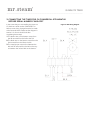
Figure 1: Wiring Diagram
SETTING A RUNNING TIME
Using the button, you can set the desired running time during
which the steam generator will operate. The steam solenoid
connected to the timer is switched on. As the timer counts
down, the corresponding light will illuminate indicating the
amount of time left.
END OF RUNNING TIME
After the preset running time has elapsed, the timer switches
the connected steam solenoid off. The red light indicating the
steam is off will be illuminated.
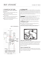
2. STEAM VENT
IMPORTANT: A steam vent (PN 104072) must be installed
in the steam line between the steam generator and the steam
solenoid valve when using a 30 minute timer as shown. The
steam vent will release hydrostatic pressure in the boiler while
filling when the 30 minute timer has timed out.
Make sure the boiler and pipes are not hot and
have no pressure before installing the steam vent.
1.The steam vent shall be plumbed into a Tee in the steam
line between the boiler and the solenoid valve. Only one
steam vent is required, even if the boiler services two
rooms.
2.IMPORTANT NOTE: The steam vent should remain
accessible for service.
3.The steam vent should be oriented vertically, with the
threads down, as shown in Figure 2.
4.The steam vent is provided with 3/4” NPT male and 1/2”
NPT female thread for connecting to the steam line.
Steam Generator
Steam Vent
Figure 4
Figure 2
1. CONNECTING THE TIMER
If CU serial number is before CXA1247817,
see section 3.
1.Remove one of the knockout holes on the
left side of the boiler jacket.
2.Remove the room timer jumper from the
terminal block.
3.Connect the timer to the terminal block as
shown on the wiring diagram Figure 1.
4.Mount the timer plate assembly on a 4 x 2
Electrical box (not supplied).
TIMER
SWITCH
PN: 104561
STEAM
SOLENOID
VALVE
DIGITAL 1 CONTROL
N
WHT
L
BLK
S
BLK
BLK
BRN
L
BLK
WHT
RED
BLK
WHT
WHT
GRN
REMOVE
JUMPER
WHEN
INSTALLING
TIMER

mr.steam®
30-MINUTE TIMER
________________________________________________________________________________________________________________________________________________
3. CONNECTING THE TIMER FOR CU COMMERCIAL STEAMBATHS
BEFORE SERIAL NUMBER CXA1247817
Figure 3: Old Wiring Diagram
In the event that you are installing the timer to a
CU that has a serial number CXA1247817 or
before, some wiring changed need to be made
at the terminal block. Please see the diagram in
section 1 for how it should look after
completing these steps.
1.The brown wire on the bottom moves from
the 4th terminal from the left to the 5th.
2.The black wire on the bottom moves from the
3rd terminal from the left to the 4th.
3.The metal jumper moves from between the
4th and 5th terminal from the left on the top
to between the 3rd and 4th on the bottom.
-
 1
1
-
 2
2
-
 3
3


MrSteam Digital 30-Minute Timer Installation & Operation Manual
- Tipo
- Installation & Operation Manual
in altre lingue
- English: MrSteam Digital 30-Minute Timer
Altri documenti
-
Sharp R-23AM Manuale utente
-
 Brasilia Gradisca Manuale utente
-
Carel compactSteam Manuale utente
-
Sea Ray 2000 330 EXPRESS CRUISER Manuale del proprietario
-
Carel compactSteam XL Manuale utente
-
Speed Queen Super 20 CL8771 Manuale utente
-
 N&W Global Vending Koro Prime Espresso Installation, Operation & Maintenance Manual
-
Miller BLUE STAR 2E Manuale del proprietario
-
Weil-McLain CE Manuale utente

