NEC AccuSync® LCD224WM Manuale del proprietario
- Categoria
- TV
- Tipo
- Manuale del proprietario

AccuSync LCD224WM
User’s Manual
Bedienerhandbuch
Manual del usuario
Manuel Utilisateur
Manuale utente
Руководство пользователя
Kullan∂c∂ Kılavuzu
00_Cover 16/11/07, 11:02 AM1

TCO’03
Congratulations!
The display you have just purchased carries the TCO’03 Displays
label. This means that your display is designed, manufactured and
tested according to some of the strictest quality and environmental
requirements in the world. This makes for a high performance
product, designed with the user in focus that also minimizes the
impact on our natural environment.
Some of the features of the TCO’03 Display requirements:
Ergonomics
• Good visual ergonomics and image quality in order to improve the working environment for
the user and to reduce sight and strain problems. Important parameters are luminance,
contrast, resolution, reflectance, colour rendition and image stability.
Energy
• Energy-saving mode after a certain time – beneficial both for the user and the environment
• Electrical safety
Emissions
• Electromagnetic fields
• Noise emissions
Ecology
• The product must be prepared for recycling and the manufacturer must have a certified
environmental management system such as EMAS or ISO 14 001
• Restrictions on:
- chlorinated and brominated flame retardants and polymers
- heavy metals such as cadmium, mercury and lead.
The requirements included in this label have been developed by TCO Development in co-operation
with scientists, experts, users as well as manufacturers all over the world. Since the end of the
1980s TCO has been involved in influencing the development of IT equipment in a more user-
friendly direction. Our labelling system started with displays in 1992 and is now requested by users
and IT-manufacturers all over the world.
For more information, please visit
www.tcodevelopment.com
00_Cover 16/11/07, 11:02 AM2

WEEE Mark (European Directive 2002/96/EC)
Within the European Union
EU-wide legislation, as implemented in each Member State, requires that waste
electrical and electronic products carrying the mark (left) must be disposed of
separately from normal household waste. This includes monitors and electrical
accessories, such as signal cables or power cords. When you need to dispose of
your NEC display products, please follow the guidance of your local authority, or
ask the shop where you purchased the product, or if applicable, follow any
agreements made between yourself and NEC.
The mark on electrical and electronic products only applies to the current European Union Member
States.
Outside the European Union
If you wish to dispose of used electrical and electronic products outside the European Union, please
contact your local authority so as to comply with the correct disposal method.
Manufacturer’s Recycling and Energy Information
NEC DISPLAY SOLUTIONS is strongly committed to environmental protection and sees recycling
as one of the company’s top priorities in trying to minimize the burden placed on the environment.
We are engaged in developing environmentally-friendly products, and always strive to help define
and comply with the latest independent standards from agencies such as ISO (International
Organisation for Standardization) and TCO (Swedish Trades Union).
Disposing of your old NEC product
The aim of recycling is to gain an environmental benefit by means of re-use, upgrading,
reconditioning or reclamation of material. Dedicated recycling sites ensure that environmentally
harmful components are properly handled and securely disposed. To ensure the best recycling of
our products, NEC DISPLAY SOLUTIONS offers a variety of recycling procedures and gives
advice on how to handle the product in an environmentally sensitive way, once it has reached the
end of its life.
All required information concerning the disposal of the product and country-specific information on
recycling facilities can be found on our following websites:
http://www.nec-display-solutions.com/greencompany/ (in Europe),
http://www.nec-display.com (in Japan) or
http://www.necdisplay.com (in USA).
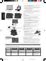
Energy Saving
This monitor features an advanced energy saving capability. When a VESA Display Power
Management Signalling (DPMS) Standard signal is sent to the monitor, the Energy Saving mode is
activated. The monitor enters a single Energy Saving mode.
Mode Power consumption LED colour
Normal Operation Approx. 50W Green
Energy Saving Mode Less than 2W Amber
Off Mode Less than 1W Unlit
00_Cover 16/11/07, 11:02 AM3

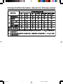
Chinese RoHS-information relevant for Chinese market
00_Cover 16/11/07, 11:02 AM4

English-1
English
Declaration of the Manufacturer
We hereby certify that the colour monitor AccuSync LCD224WM
(L227HK) is in compliance with
Council Directive 73/23/EEC:
– EN 60950-1
Council Directive 89/336/EEC:
– EN 55022
– EN 61000-3-2
– EN 61000-3-3
– EN 55024
RISK OF ELECTRIC SHOCK • DO NOT OPEN
TO PREVENT FIRE OR SHOCK HAZARDS, DO NOT EXPOSE THIS UNIT TO RAIN OR MOISTURE. ALSO, DO NOT USE THIS UNIT’S
POLARIZED PLUG WITH AN EXTENSION CORD RECEPTACLE OR OTHER OUTLETS UNLESS THE PRONGS CAN BE FULLY INSERTED.
REFRAIN FROM OPENING THE CABINET AS THERE ARE HIGH VOLTAGE COMPONENTS INSIDE. REFER SERVICING TO QUALIFIED
SERVICE PERSONNEL.
WARNING
CAUTION: TO REDUCE THE RISK OF ELECTRIC SHOCK,
DO NOT REMOVE COVER (OR BACK). NO USER
SERVICEABLE PARTS INSIDE. REFER SERVICING
TO QUALIFIED SERVICE PERSONNEL.
This symbol warns user that uninsulated voltage
within the unit may have sufficient magnitude to cause
electric shock. Therefore, it is dangerous to make any
kind of contact with any part inside this unit.
This symbol alerts the user that important literature
concerning the operation and maintenance of this
unit has been included. Therefore, it should be read
carefully in order to avoid any problems.
CAUTION
and marked with
NEC Display Solutions, Ltd.
4-13-23, Shibaura,
Minato-Ku
Tokyo 108-0023, Japan
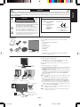
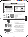
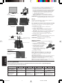
Contents
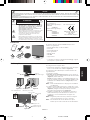
Your new NEC AccuSync LCD monitor box* should contain the
following:
• AccuSync LCD monitor with tilt base
• Audio Cable
• Power Cord
•Video Signal Cable
• User’s Manual
• CD-ROM
• Base Stand
*
Remember to save your original box and packing material to
transport or ship the monitor.
User’s Manual
Audio
Cable
Power Cord
Video Signal
Cable
Base Stand AccuSync LCD monitor
(base stand not connected)
CD-ROM
Quick Start
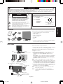
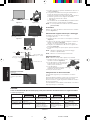
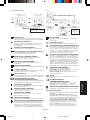
To attach the Base to the LCD Stand:
1. Attach the Base to the Stand. The locking tabs on the Stand
should fit into the hole on the Base (Figure S.1).
To attach the AccuSync LCD monitor to your system, follow these
instructions:
1. Turn off the power to your computer.
2. For the PC with Analog output: Connect the 15-pin mini D-SUB
signal cable to the connector of the display card in your system
(Figure A.1). Tighten all screws.
For the Mac: Connect the MultiSync Macintosh cable adapter (not
included) to the computer. Attach the 15-pin mini D-SUB signal
cable to the MultiSync Macintosh cable adapter (Figure A.2).
Tighten all screws.
NOTE: Some Macintosh systems do not require a Macintosh cable
adapter.
3. Connect the 15-pin mini D-SUB of the video signal cable and
Audio Cable to the appropriate connector on the back of the
monitor (Figure B.1). Connect the Headphone (not included) to
the appropriate connector at the left of the monitor (Figure C.1).
4. Connect one end of the power cord to the monitor and the other
end to the power outlet. Place the Video Signal Cable and power
cord to the Cable holder (Figure B.1).
NOTE: Adjust position of cable placed to the Cable holder to avoid
damage for cable or monitor.
NOTE: Please refer to Caution section of this manual for proper
selection of power cord.
Figure S.1
Base
Locking Tabs
Stand
Figure A.1 Figure A.2
Macintosh Cable
Adapter (not included)
Figure B.1
Cable holder
Audio Input
Input (D-Sub)
Connect to Computer
audio output
Power Cord
User’s
Manual
01_English 16/11/07, 11:02 AM1

English-2
English
Locking tabs
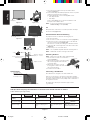
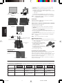
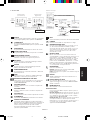
5. Turn on the monitor with the bottom power button and the
computer (Figure C.1).
6. No-touch Auto Adjust automatically adjusts the monitor to optimal
settings upon initial setup for most timings.
For further adjustments, use the following OSD controls:
• Auto Adjust Contrast
• Auto Adjust
Refer to the Controls section of this User’s Manual for a full
description of these OSD controls.
NOTE: If you have any problem, please refer to the
Troubleshooting section (CD-ROM).
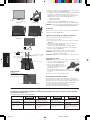
Tilt
Grasp both sides of the monitor screen with your hands and adjust
the tilt as desired (Figure TS.1).
Remove Monitor Stand for Mounting
To prepare the monitor for alternative mounting purposes:
1. Disconnect all cables.
2. Place monitor face down on a non-abrasive surface (Figure R.1).
3. Remove the 2 screws connecting the monitor to the stand and
remove the stand as indicated (Figure R.2).
The monitor is now ready for mounting in an alternative manner.
4. Connect the AC cord and signal cable to the back of the monitor
(Figure R.3).
5. Reverse this process to re-attach stand.
NOTE: Use only VESA-compatible alternative mounting method.
NOTE: Handle with care when removing monitor stand.
Removing the Base
NOTE: Always remove the Base when shipping the LCD.
1. Place monitor face down on a non-abrasive
surface (Figure R.1).
2. While using your fingers, press the 3 locking
tabs of left or right side at the same time
to unlock the Base.
3. While using your fingers, press the
3 locking tabs of another side at the same
time to unlock the Base.
4. Pull out the unlocked Base.
Connecting a Flexible Arm
This LCD monitor is designed for use with a flexible arm.
Please use screws (4pcs) as shown in the picture when installing.
To meet the safety requirements, the monitor must be mounted to an
arm which, guaranties the necessary stability under consideration of
the weight of the monitor.
The LCD monitor shall only be used with an approved arm
(e.g. GS mark).
Headphone
Figure C.1
Power Button
Figure TS.1
Figure R.1
Non-abrasive surface
Figure R.2
Figure R.3
4-SCREWS (M4)
(MAX depth: 10 mm)
If use other screw,
check depth of hole.
Weight of LCD assembly: 4.8 kg (MAX)
Specifications
Tighten all screws
100 mm
Thickness of Bracket
(Arm) 2.0 ~ 3.2 mm
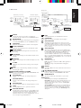
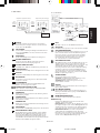
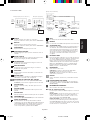
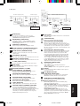
Controls
OSD (On-Screen Display) control buttons on the front of the monitor function as follows:
1. Basic function at pressing each key
Showing OSD. Shortcut to Bright adjust
window.
Button
At No OSD
showing
Shortcut to Volume adjust
window.
At OSD showing
(Icon selection stage)
Go to Adjustment stage. Cursor goes to left. Cursor goes to right.
At OSD showing
(Adjustment stage)
Go to Icon selection stage. Adjust value decrease or
Cursor for adjust goes to
left.
Adjust value increase or
Cursor for adjust goes to
right.
SELECT
– +
“Auto adjust” operate.
Reset operation.
Mute off/on switch on
Volume adjustment window.
AUTO/RESET
4 x 12 mm with lock washer
and flat washer
M4
12 mm
100 mm
01_English 16/11/07, 11:02 AM2

English-3
English
AUDIO
Controls the volume of the speakers or headphones.
To mute the speaker output, press the “AUTO/RESET” button.
BRIGHTNESS
Adjusts the overall image and background screen brightness.
To enter the ECO MODE, press the “AUTO/RESET” button.
CONTRAST
Adjusts the image brightness in relation to the background.
AUTO CONTRAST
Adjusts the image displayed for non-standard video inputs.
AUTO ADJUST
Automatically adjusts the Image Position, the H. Size and
Fine setting.
LEFT/RIGHT
Controls Horizontal Image Position within the display area of
the LCD.
DOWN/UP
Controls Vertical Image Position within the display area of the
LCD.
H. SIZE
Adjusts the horizontal size by increasing or decreasing this
setting.
FINE
Improves focus, clarity and image stability by increasing or
decreasing this setting.
COLOUR CONTROL SYSTEMS
Five colour presets (9300/7500/sRGB/USER/NATIVE) select
the desired colour setting.
COLOUR RED
Increase or decreases Red. The change will appear on
screen.
COLOUR GREEN
Increase or decreases Green. The change will appear on
screen.
COLOUR BLUE
Increase or decreases Blue. The change will appear on screen.
TOOL
Selecting TOOL allows you to get into the sub menu.
FACTORY PRESET
Selecting Factory Preset allows you to reset all OSD control
settings back to the factory settings. The RESET button will
need to be held down for several seconds to tage effect.
Individual settings can be reset by highlighting the control to
be reset and pressing the RESET button.
EXIT
Selecting EXIT allows you exit OSD menu/ sub menu.
LANGUAGE
OSD control menus are available in nine languages.
OSD TURN OFF
The OSD control menu will stay on as long as it is in use.
In the OSD Turn OFF submenu, you can select how long the
monitor waits after the last touch of a button to shut off the
OSD control menu. The preset choices are 10 - 120 seconds
by 5 seconds step.
OSD LOCK OUT
This control completely locks out access to all OSD control
functions without Brightness and Contrast. When attempting
to activate OSD controls while in the Lock Out mode, a
screen will appear indicating the OSD are locked out. To
activate the OSD Lock Out function, press “AUTO/ RESET”,
then “+” key and hold down simultaneously. To de-activate the
OSD Lock Out, press “AUTO/ RESET”, then “+” key and hold
down simultaneously.
EXPANSION
Selects the zoom mode.
FULL: The image is expanded to 1680 x 1050, regardless of
the resolution.
ASPECT: The image is expanded without changing the
aspect ratio.
DDC/CI
Turns ON or OFF the two way communication and control of
the monitor.
ECO MODE NOTIFIER
If ON is selected, a message will appear on the screen after
power on, notifying you that ECO MODE is ON or OFF.
MONITOR INFO
Indicates the model and serial numbers of your monitor.
OSD Warning
OSD Warning menus disappear with SELECT button.
NO SIGNAL: This function gives a warning when there is no
signal present. After power is turned on or when there is a
change of input signal or video is inactive, the No Signal
window will appear.
OUT OF RANGE: This function gives a recommendation of
the optimized resolution and refresh rate. After the power is
turned on or there is a change of input signal or the video
signal doesn’t have proper timing, the Out Of Range menu
will appear.
2. OSD structure
Sub Menu
(Icon Select)
Press
“–” or “+”
Sub Menu (Adjust)
Press “SELECT” key
Press
“–” or “+”
Example Tool:
Press “SELECT” key
Press “SELECT” key
Main Menu (Icon Select) Main Menu (Adjust)
Press
“SELECT”
key
Press
“SELECT”
key
Press “SELECT” key
Adjust by using
“–” or “+”
Adjust by using
“–” or “+”
01_English 16/11/07, 11:02 AM3

Deutsch-1
Deutsch
Erklärung des Herstellers
Wir bestätigen hiermit, dass der Farbmonitor AccuSync LCD224WM
(L227HK) folgenden Richtlinien entspricht:
EG-Direktive 73/23/EG:
– EN 60950-1
EG-Direktive 89/336/EG:
– EN 55022
– EN 61000-3-2
– EN 61000-3-3
– EN 55024
STROMSCHLAGGEFAHR • NICHT ÖFFNEN
SETZEN SIE DAS GERÄT WEDER REGEN NOCH FEUCHTIGKEIT AUS, DA ES ANDERNFALLS ZU FEUER ODER STROMSCHLÄGEN KOMMEN
KANN. VERWENDEN SIE DEN NETZSTECKER DIESES GERÄTS KEINESFALLS MIT EINEM VERLÄNGERSKABEL ODER EINER
STECKDOSENLEISTE, WENN DIE STECKERSTIFTE NICHT VOLLSTÄNDIG EINGEFÜHRT WERDEN KÖNNEN.
ÖFFNEN SIE DAS GEHÄUSE NICHT, DA SICH IM INNEREN KOMPONENTEN BEFINDEN, DIE UNTER HOCHSPANNUNG STEHEN. LASSEN SIE
WARTUNGSARBEITEN VON QUALIFIZIERTEN WARTUNGSTECHNIKERN DURCHFÜHREN.
WARNUNG
VORSICHT: ENTFERNEN SIE KEINESFALLS ABDECKUNG ODER
RÜCKSEITE, DAMIT ES NICHT ZU STROMSCHLÄGEN
KOMMT. IM INNEREN BEFINDEN SICH KEINE VOM
BENUTZER ZU WARTENDEN KOMPONENTEN. LASSEN
SIE WARTUNGSARBEITEN VON QUALIFIZIERTEN
WARTUNGSTECHNIKERN DURCHFÜHREN.
Dieses Symbol weist den Benutzer auf nicht isolierte
spannungsführende Komponenten im Gerät hin, die
Stromschläge verursachen können. Aus diesem Grund
dürfen Sie keinesfalls Kontakt mit einer Komponente im
Geräteinneren herstellen.
Dieses Symbol weist den Benutzer auf wichtige
Informationen zu Betrieb und Pflege dieses Geräts hin.
Die Informationen sollten sorgfältig gelesen werden, um
Probleme zu vermeiden.
VORSICHT
und mit folgendem Siegel
gekennzeichnet ist:
NEC Display Solutions, Ltd.
4-13-23, Shibaura,
Minato-Ku
Tokyo 108-0023, Japan
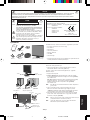
Inhalt der Verpackung
Der Karton* mit Ihrem neuen NEC AccuSync LCD-Monitor sollte
folgende Komponenten enthalten:
• AccuSync LCD-Monitor mit verstellbarem Fuß
• Audiokabel
• Netzkabel
• Signalkabel
• Bedienungsanleitung
• CD-ROM
• Standfuß
*
Bewahren Sie den Originalkarton und das Verpackungsmaterial
für spätere Transporte des Monitors auf.
Bedienung-
sanleitung
Audiokabel
Netzkabel
Signalkabel
Standfuß AccuSync LCD-Monitor
(Standfuß nicht montiert)
Kurzanleitung
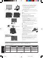
So befestigen Sie den Standfuß am Fuß des LCD-Monitors:
1. Befestigen Sie den Standfuß am Monitor. Die Verriegelungen an
der Unterseite des Monitors müssen in die Aussparung des
Standfußes einrasten (Abbildung S.1).
Gehen Sie folgendermaßen vor, um den AccuSync LCD-Monitor an
Ihr System anzuschließen:
1. Schalten Sie Ihren Computer aus.
2. PC mit analogem Ausgang: Verbinden Sie den Mini-D-SUB-
Stecker (15 Stifte) des entsprechenden Signalkabels mit dem
Anschluss der Grafikkarte in Ihrem System (Abbildung A.1).
Ziehen Sie die Schrauben fest.
Mac: Schließen Sie den MultiSync-Kabeladapter für Macintosh
(nicht mitgeliefert) an den Computer an. Stecken Sie den Mini-D-
SUB-Stecker (15 Stifte) des Signalkabels in den Macintosh-
Kabeladapter (Abbildung A.2). Ziehen Sie die Schrauben fest.
HINWEIS: Für einige Macintosh-Systeme ist kein Macintosh-
Kabeladapter erforderlich.
3. Stecken Sie den Mini-D-SUB-Stecker (15 Stifte) des
Videosignalkabels und das Audiokabel in die entsprechenden
Buchsen auf der Rückseite des Monitors (Abbildung B.1).
Stecken Sie den Kopfhörer (nicht mitgeliefert) in die
entsprechende Buchse auf der linken Seite des Monitors
(Abbildung C.1).
4. Stecken Sie ein Ende des Netzkabels in den Monitor und das
andere Ende in die Steckdose. Führen Sie das Signalkabel und
Netzkabel durch den Kabelhalter (Abbildung B.1).
HINWEIS: Bringen Sie die Kabel so in der Kabelhalterung an, dass
weder Kabel noch Monitor beschädigt werden können.
HINWEIS: Beachten Sie zur Auswahl des richtigen Netzkabels den
entsprechenden Sicherheitshinweis in dieser
Bedienungsanleitung.
CD-ROM
Abbildung S.1
Standfuß
Verriegelungen
Monitorfuß
Abbildung A.1 Abbildung A.2
Macintosh-
Kabeladapter
(nicht mitgeliefert)
Abbildung B.1
Kabelhalter
Audioeingang
Eingang (D-Sub)
An Audio-Ausgang des
Computers anschließen
Netzkabel
Bedienung-
sanleitung
02_German 16/11/07, 11:02 AM1

Deutsch-2
Deutsch
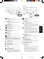
Bedienelemente
Die OSD-Bedienelemente (On-Screen-Display) auf der Vorderseite des Monitors haben folgende Funktionen:
1. Basisfunktion beim Betätigen der jeweiligen Taste
Zeigt den OSD an. Öffnet das Fenster für die
Helligkeitseinstellung.
Taste
Ohne OSD-
Anzeige
Öffnet das Fenster für die
Lautstärkeeinstellung.
Mit OSD-Anzeige
(
Symbolauswahlmodus
)
Wechselt zur
Einstellungsphase.
Cursor nach links. Cursor nach rechts.
Mit OSD-Anzeige
(Einstellungsmodus)
Wechselt zum
Symbolauswahlmodus.
Verringert den Wert oder
bewegt Cursor nach links.
Erhöht den Wert oder
bewegt Cursor nach rechts.
SELECT
– +
Aktiviert die automatische
Einstellung.
Zurücksetzen der Einstellung.
Schaltet im Fenster für die
Lautstärkeeinstellung die
Stummschaltung ein/aus.
AUTO/RESET
Verriegelungen
KOPFHÖRER
Abbildung C.1
Netzschalter
Abbildung TS.1
Abbildung R.1
Weiche Oberfläche
Abbildung R.2
Abbildung R.3
4 SCHRAUBEN (M4)
(maximale Tiefe: 10 mm)
Wenn Sie andere Schrauben
verwenden, prüfen Sie die
Tiefe der Bohrung.
Gewicht des LCD-Monitors komplett: 4,8 kg (max.)
Technische Daten
Alle Schrauben
festziehen
100 mm
Stärke der Halterung
(Arm) 2,0 ~ 3,2 mm
4 x 12 mm mit Federring
und Federscheibe
M4
12 mm
100 mm
5. Schalten Sie den Computer und den Monitor mit dem Netzschalter
an der Unterseite (Abbildung C.1) ein.
6. Die berührungslose Einstellungsautomatik nimmt beim ersten
Setup für die meisten Timings die optimalen Einstellungen für den
Monitor vor. Weitere Anpassungen werden mit den folgenden
OSD Steuerungen vorgenommen:
• Automatische Kontrasteinstellung
• Automatische Einstellung
Im Abschnitt Bedienelemente dieser Bedienungsanleitung finden
Sie eine ausführliche Beschreibung der OSD-Steuerungen.
HINWEIS: Sollten Probleme auftreten, beachten Sie den Abschnitt
Fehlerbehebung (CD-ROM).
Neigen
Fassen Sie den Monitor an beiden Seiten und neigen Sie ihn nach
Bedarf (Abbildung TS.1).
Entfernen des Monitorfußes für die Montage
So bereiten Sie den Monitor für eine alternative Montage vor:
1. Ziehen Sie alle Kabel ab.
2. Legen Sie den Monitor mit der Vorderseite nach unten auf eine
weiche Oberfläche (Abbildung R.1).
3. Entfernen Sie die 2 Schrauben, mit denen der Fuß am Monitor
befestigt ist, und heben Sie den Fuß ab (Abbildung R.2).
Der Monitor kann jetzt auf andere Art montiert werden.
4. Schließen Sie Netz- und Signalkabel an der Rückseite des
Monitors an (Abbildung R.3).
5. Führen Sie die Schritte in umgekehrter Reihenfolge aus, um den
Fuß wieder anzubringen.
HINWEIS: Verwenden Sie ausschließlich VESA-kompatible
Montagemethoden.
HINWEIS: Entfernen Sie den Monitorfuß vorsichtig.
Entfernen des Standfußes
HINWEIS: Entfernen Sie den Standfuß vor dem Versenden des
Monitors.
1. Legen Sie den Monitor mit der Vorderseite
nach unten auf eine weiche Oberfläche
(Abbildung R.1).
2. Drücken Sie mit Ihren Fingern
gleichzeitig auf die 3 Verriegelungen
entweder auf der rechten oder auf der
linken Seite, um den Fuß zu lösen.
3. Drücken Sie mit Ihren Fingern gleichzeitig auf die
3 Verriegelungen auf der anderen Seite, um den Fuß zu lösen.
4. Ziehen Sie den gelösten Fuß heraus.
Befestigen eines Tragarms
Dieser LCD-Monitor kann mit einem Tragarm verwendet werden.
Verwenden Sie die beigefügten Schrauben (4 Stück) für die Montage,
wie es in der Abbildung dargestellt ist. Die Sicherheitsvorschriften
verlangen, dass der Monitor an einem Tragarm montiert wird, der für
das Gewicht des Monitors ausreichend stabil ist.
Der LCD-Monitor darf nur auf einem zugelassenen Arm montiert
werden, der beispielsweise mit einem GS-Zeichen versehen ist.
02_German 16/11/07, 11:02 AM2

Deutsch-3
Deutsch
2. OSD Struktur
AUDIO
Regelt die Lautstärke der Lautsprecher oder Kopfhörer.
Um die Lautsprecherausgabe stumm zu schalten, drücken
Sie die Taste „AUTO/RESET“.
HELLIGKEIT
Passt die Bild- und Hintergrundhelligkeit des Bildschirms an.
Um in den ECO MODE zu wechseln, drücken Sie die Taste
„AUTO/RESET“.
KONTRAST
Ändert die Bildhelligkeit im Verhältnis zum Hintergrund.
AUTOM. KONTRAST
Passt das angezeigte Bild bei Verwendung nicht dem
Standard entsprechender Eingangssignale an.
AUTOM. EINSTELLUNG
Stellt Bildposition, Bildbreite und Optimierung automatisch ein.
LINKS/RECHTS
Steuert die horizontale Bildposition im Anzeigebereich des LCD.
AUF/AB
Steuert die vertikale Bildposition im Anzeigebereich des LCD.
BILDBREITE
Durch Erhöhen oder Verringern dieses Werts wird das Bild
breiter bzw. schmaler.
OPTIMIERUNG
Optimiert Schärfe, Deutlichkeit und Bildstabilität durch
Erhöhen oder Verringern dieses Werts.
FARBSTEUERUNGSSYSTEM
Fünf vordefinierte Farbeinstellungen (9300/7500/sRGB/
BENUTZER/ORIGINALFARBEN).
FARBE ROT
Erhöht oder verringert den Rotanteil. Die Änderung wird auf
dem Bildschirm sichtbar.
FARBE GRÜN
Erhöht oder verringert den Grünanteil. Die Änderung wird auf
dem Bildschirm sichtbar.
FARBE BLAU
Erhöht oder verringert den Blauanteil. Die Änderung wird auf
dem Bildschirm sichtbar.
WERKZEUG
Durch Auswahl von WERKZEUG gelangen Sie in das Untermenü.
WERKSEINSTELLUNG
Mit der OSD-Steuerung „Werkseinstellung“ werden alle OSD-
Einstellungen auf die Werkseinstellungen zurückgesetzt. Sie
müssen die Taste RESET mehrere Sekunden halten, um die
Rücksetzung durchzuführen. Einzelne Einstellungen können
durch Markieren der betreffenden Steuerung und anschließendes
Drücken der Taste RESET zurückgesetzt werden.
EXIT
Mit „EXIT“ verlassen Sie das OSD Menü/Untermenü.
SPRACHE
Die OSD-Steuerungsmenüs sind in neun Sprachen verfügbar.
OSD ANZEIGEDAUER
Das OSD Steuerungsmenü wird ausgeblendet, wenn es nicht
mehr verwendet wird. Im Untermenü „OSD Anzeigedauer“
können Sie festlegen, nach welchem Zeitraum das OSD
Steuerungsmenü ausgeblendet wird, wenn der Benutzer
keine Taste drückt. Die Voreinstellungen reichen von
10 – 120 Sekunden in 5-Sekunden-Abständen.
OSD ABSCHALTUNG
Mit „OSD Abschaltung“ werden alle OSD-Funktionen bis auf
„Helligkeit“ und „Kontrast“ gesperrt. Wenn Sie im Modus
„OSD Abschaltung“ auf die OSD Steuerungen zugreifen, wird
ein Bildschirm angezeigt, der auf die Sperre der OSD
Steuerungen hinweist. Um die Funktion „OSD Abschaltung“
zu aktivieren, halten Sie die Tasten AUTO/RESET und „+“
gleichzeitig gedrückt. Um die Funktion „OSD Abschaltung“
wieder zu deaktivieren, drücken Sie erneut die Taste AUTO/
RESET und gleichzeitig die Taste „+“.
AUSDEHNUNG
Dient zum Auswählen des Zoom-Modus.
VOLLBILD: Die Bilddarstellung wird unabhängig von der
Auflösung auf 1680 x 1050 Pixel erweitert.
SEITENMASSE: Das Bild wird vergrößert, ohne das
Seitenverhältnis zu ändern.
DDC/CI
Schaltet die 2-Wege-Kommunikation und die Steuerung des
Monitors EIN oder AUS.
ECO MODE-ANZEIGE
Wenn Sie AN auswählen, wird nach dem Einschalten eine
Meldung auf dem Bildschirm angezeigt, ob ECO MODE ein-
oder ausgeschaltet ist.
MONITORINFORMATION
Die Modell- und die Seriennummer des Monitors.
OSD Warnung
Die Menüs der OSD Warnungen können mit der Taste
„SELECT“ ausgeblendet werden.
KEIN SIGNAL: Diese Funktion gibt eine Warnung aus, wenn
kein Signal verfügbar ist. Das Fenster Kein Signal wird nach
dem Einschalten oder einem Wechsel des Eingangssignals
sowie dann angezeigt, wenn kein Videosignal verfügbar ist.
FREQUENZ ZU HOCH: Diese Funktion empfiehlt die
optimale Auflösung und Bildwiederholrate. Nach dem
Einschalten, nach einer Änderung des Eingangssignals oder
wenn das Videosignal nicht die richtige Auflösung besitzt,
wird das Fenster Frequenz zu hoch angezeigt.
Untermenü
(Symbolauswahl)
Taste
„–“ oder „+“
drücken
Untermenü (Einstellungen)
Taste „SELECT“ drücken
Taste
„–“ oder „+“
drücken
Beispiel WERKZEUG:
Taste „SELECT“ drücken
Taste „SELECT“ drücken
Hauptmenü (Symbolauswahl) Hauptmenü (Einstellungen)
Taste
„SELECT“
drücken
Taste
„SELECT“
drücken
Taste „SELECT“ drücken
Mit „–“ oder „+“
einstellen
Mit „–“ oder „+“
einstellen
02_German 16/11/07, 11:02 AM3

Español-1
Español
Declaración del fabricante
Por la presente certificamos que el monitor en color AccuSync
LCD224WM (L227HK) cumple la
Directiva 73/23/CEE:
– EN 60950-1
Directiva 89/336/CEE:
– EN 55022
– EN 61000-3-2
– EN 61000-3-3
– EN 55024
RIESGO DE DESCARGAS ELÉCTRICAS • NO ABRIR
PARA PREVENIR EL PELIGRO DE INCENDIO O DESCARGAS ELÉCTRICAS, NO EXPONGA ESTE PRODUCTO A LA LLUVIA O LA HUMEDAD.
TAMPOCO UTILICE EL ENCHUFE POLARIZADO DE ESTE PRODUCTO CON UN RECEPTÁCULO DEL CABLE DE EXTENSIÓN U OTRAS TOMAS A
MENOS QUE LAS PROLONGACIONES SE PUEDAN INSERTAR COMPLETAMENTE.
NO ABRA LA CAJA DEL MONITOR, YA QUE CONTIENE COMPONENTES DE ALTO VOLTAJE. DEJE QUE SEA EL PERSONAL DE SERVICIO
CUALIFICADO QUIEN SE ENCARGUE DE LAS TAREAS DE SERVICIO.
ADVERTENCIA
PELIGRO: PARA REDUCIR EL RIESGO DE DESCARGAS
ELÉCTRICAS, NO RETIRE LA CUBIERTA (O LA PARTE
POSTERIOR). EL MONITOR NO CONTIENE PIEZAS QUE
DEBA MANIPULAR EL USUARIO. DEJE QUE SEA EL
PERSONAL DE SERVICIO CUALIFICADO QUIEN SE
ENCARGUE DE LAS TAREAS DE SERVICIO.
Este símbolo advierte al usuario de que el producto puede
contener suficiente voltaje sin aislar como para
causar descargas eléctricas. Por tanto, evite el contacto con
cualquier pieza del interior del monitor.
Este símbolo advierte al usuario de que se incluye
documentación importante respecto al funcionamiento y el
mantenimiento de este producto. Por ello, debería leerla
atentamente para evitar problemas.
PELIGRO
y lleva la marca
NEC Display Solutions, Ltd.
4-13-23, Shibaura,
Minato-Ku
Tokyo 108-0023, Japón
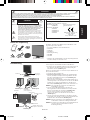
Contenido
Su nueva caja* de monitor LCD AccuSync NEC debería contener:
• Un monitor LCD AccuSync con base inclinable
• Cable de audio
• Cable de alimentación
• Cable de señal de vídeo
• Manual del usuario
• CD-ROM
• Base
*
Recuerde conservar la caja y el material de embalaje originales
para poder transportar el monitor en el futuro.
Manual del
usuario
Cable de
audio
Cable de
alimentación
Cable de señal
de vídeo
Base Monitor LCD AccuSync
(base no conectada)
Inicio rápido
Para conectar la base al soporte del monitor:
1. Conecte la base al soporte. Las lengüetas de sujeción del soporte
deberían encajar en el orificio de la base (figura S.1).
Para conectar el monitor LCD AccuSync a su sistema, siga estas
indicaciones:
1. Apague el ordenador.
2. Para PC con salida analógica: conecte el cable de señal del
mini D-SUB de 15 clavijas al conector de la tarjeta de
visualización de su sistema (figura A.1). Apriete todos los
tornillos.
Para los Mac: conecte el adaptador para Macintosh de MultiSync
(no incluido) al ordenador. Conecte el cable de señal del mini
D-SUB de 15 clavijas al adaptador para Macintosh de MultiSync
(figura A.2). Apriete todos los tornillos.
NOTA: algunos sistemas Macintosh no necesitan adaptador.
3. Conecte el mini D-SUB de 15 clavijas del cable de señal de vídeo
y el cable de audio al conector adecuado en la parte posterior del
monitor (figura B.1). Conecte los auriculares (no incluidos) al
conector apropiado de la parte izquierda del monitor (figura C.1).
4. Conecte un extremo del cable de alimentación al monitor y el otro
a la toma de corriente. Introduzca el cable de señal de vídeo y el
de alimentación en el pasacables (figura B.1).
NOTA: ajuste la posición del cable del pasacables para evitar
daños en él y el monitor.
NOTA:
consulte el apartado Peligro de este manual para
asegurarse de que selecciona el cable de alimentación
adecuado.
CD-ROM
Figura S.1
Base
Lengüetas de sujeción
Soporte
Figura A.1 Figura A.2
Adaptador para
Macintosh (no incluido)
Figura B.1
Pasacables
Entrada de audio
Entrada (D-Sub)
Conecte la salida de
audio del ordenador
Cable de alimentación
Manual
del
usuario
03_Spain 16/11/07, 11:03 AM1

Español-2
Español
Controles
Los botones de control OSD (On-Screen Display) situados en la parte frontal del monitor funcionan del siguiente modo:
1. Funciones básicas pulsando una tecla
Aparece OSD. Acceso rápido a la ventana
de ajuste del brillo.
Botón
Si no aparece
OSD
Acceso rápido a la ventana
de ajuste del volumen.
Si aparece OSD
(selección del icono)
Pasa al nivel de ajuste. El cursor se desplaza hacia
la izquierda.
El cursor se desplaza hacia
la derecha.
Si aparece OSD
(ajuste)
Pasa al nivel de selección
del icono.
Disminución del valor de
ajuste o el cursor para el
ajuste se desplaza hacia la
izquierda.
Aumento del valor de ajuste
o el cursor para el ajuste se
desplaza hacia la derecha.
SELECT
– +
Función de “Auto ajuste”.
Función de reajuste.
Silencio encendido/apagado
en la ventana de ajuste del
volumen.
AUTO/RESET
Lengüetas de sujeción
AURICULARES
Figura C.1
Botón de encendido
Figura TS.1
Figura R.1
Superficie no abrasiva
Figura R.2
Figura R.3
4 TORNILLOS (M4)
(profundidad MÁX.: 10 mm)
Si utiliza otros tornillos,
compruebe la profundidad
del orificio.
Peso del conjunto del monitor: 4,8 kg (MÁX.)
Especificaciones
Apriete todos los
tornillos
100 mm
Grosor de la escuadra
(brazo) 2,0 ~ 3,2 mm
4 arandelas de seguridad y
arandelas planas de 12 mm
M4
12 mm
100 mm
5. Encienda el monitor y el ordenador con el botón de encendido
(figura C.1).
6. Esta función No-touch ajusta automáticamente el monitor con la
configuración óptima inicial en la mayoría de cadencias.
Para llevar a cabo otros ajustes, utilice los siguientes controles de OSD:
• Contraste de autoajuste
• Auto ajuste
Consulte el apartado Controles de este manual del usuario si
desea obtener una descripción detallada de estos controles OSD.
NOTA: si surgiera algún problema, consulte la sección Solución
de problemas (CD-ROM).
Inclinación
Sostenga el monitor por ambos lados con las manos y ajuste la
inclinación que desee (figura TS.1).
Cómo retirar el soporte del monitor para el montaje
Para montar el monitor de otra forma:
1. Desconecte todos los cables.
2. Coloque el monitor boca abajo en una superficie no abrasiva
(figura R.1).
3. Retire los 2 tornillos que unen el monitor al soporte y retire el
soporte como se indica (figura R.2).
El monitor ya está preparado para montarlo de otro modo.
4. Conecte el cable de CA y el cable de señal a la parte posterior del
monitor (figura R.3).
5.
Repita el proceso en sentido inverso para volver a montar el soporte.
NOTA: utilice sólo métodos de montaje alternativos compatibles
con VESA.
NOTA: retire el soporte del monitor con cuidado.
Desmontaje de la base
NOTA: desmonte la base siempre que vaya a transportar el monitor.
1. Coloque el monitor boca abajo en una superficie
no abrasiva (figura R.1).
2. Con ayuda de sus dedos, pulse las 3
pestañas de bloqueo del lado izquierdo o
derecho al mismo tiempo para
desbloquear la Base.
3. Con ayuda de sus dedos, pulse las 3
pestañas de bloqueo del otro lado al mismo tiempo
para desbloquear la Base.
4. Tire de la base para sacarla.
Instalación de un brazo flexible
Este monitor LCD está diseñado para ser utilizado con un brazo flexible.
Para el montaje, utilice los tornillos (4) y colóquelos tal como se
muestra en la imagen. Para cumplir las normas de seguridad, el monitor
debe estar montado a un brazo que garantice la estabilidad necesaria
teniendo en cuenta el peso del monitor.
El monitor LCD sólo se podrá utilizar con un brazo homologado (por
ejemplo, de la marca GS).
03_Spain 16/11/07, 11:03 AM2

Español-3
Español
2. Estructura de OSD
AUDIO
Controla el volumen de los altavoces o auriculares.
Para poner el altavoz en silencio, pulse el botón “AUTO/RESET”.
BRILLO
Ajusta el brillo de la imagen global y del fondo.
Para poner el altavoz en silencio, pulse el botón “AUTO/RESET”.
CONTRASTE
Ajusta el brillo de la imagen respecto al fondo.
CONTRASTE AUTOM.
Ajusta la imagen que aparece para las entradas de vídeo no
estándar.
AUTO AJUSTE
Ajusta automáticamente la configuración de Image Position
(Posición de la imagen), Anchura y Estabilidad.
IZQ./DERECHA
Controla la posición horizontal de la imagen en el área de
visualización de la pantalla.
ABAJO/ARRIBA
Controla la posición vertical de la imagen en el área de
visualización de la pantalla.
ANCHURA
Ajusta el tamaño horizontal aumentando o reduciendo esta
configuración.
ESTABILIDAD
Mejora el enfoque, la claridad y la estabilidad de la imagen
aumentando o reduciendo esta configuración.
SISTEMAS DE CONTROL DEL COLOR
Con el preajuste de cinco colores (9300/7500/sRGB/USER/
ESTÁNDAR) se selecciona la configuración del color deseada.
COLOR ROJO
Aumenta o disminuye el Rojo. El cambio aparecerá en la
pantalla.
COLOR VERDE
Aumenta o disminuye el Verde. El cambio aparecerá en la
pantalla.
COLOR AZUL
Aumenta o disminuye el Azul. El cambio aparecerá en la pantalla.
HERRAMIENTA
Seleccionando TOOL (HERRAMIENTA) se accede al submenú.
CONF. DE FÁBRICA
Seleccionando Conf. de fábrica podrá restablecer todas las
configuraciones de control de OSD originales. Mantenga pulsado
el botón RESET durante unos segundos para que se active la
función. Podrá restablecer cada configuración resaltando el
control correspondiente y pulsando el botón RESET.
EXIT
Con EXIT podrá salir del menú/submenú de OSD.
IDIOMA
Los menús del control OSD están disponibles en nueve idiomas.
ACTIVIDAD OSD
El menú de control de OSD permanecerá activado mientras se
esté utilizando. En el submenú Actividad OSD puede indicar
cuánto tiempo debe transcurrir desde que se toca por última
vez un botón del menú de control de OSD hasta que éste se
desconecta. La opción preconfigurada permite un mínimo de
10 segundos y un máximo 120, variable en intervalos de
5 segundos.
BLOQUEO OSD
Este control bloquea totalmente el acceso a todas las funciones
de control de OSD excepto Brillo y Contraste. Si intenta activar
los controles de OSD mientras está activado el modo de
Bloqueo, aparecerá una ventana notificándole que los controles
de OSD están bloqueados. Para activar la función de Bloqueo
OSD, pulse “AUTO/ RESET” y la tecla “+” simultáneamente.
Para desactivar la función de Bloqueo OSD, pulse “AUTO/
RESET” y la tecla “+” simultáneamente.
EXPANSIÓN
Selecciona el modo de zoom.
COMPLETA: La imagen se amplía hasta 1680 x 1050
independientemente de cuál sea la resolución.
ASPECTO: La imagen se amplía sin modificar la relación
entre la altura y la anchura.
DDC/CI
Activa o desactiva la comunicación y control bidireccional del
monitor.
NOTIFICADOR ECO MODE
Si está activado, aparecerá un mensaje en la pantalla tras
encenderla notificándole que ECO MODE está ACTIVADO o
DESACTIVADO.
INFORMACIÓN MONITOR
Indica el número de modelo y de serie del monitor.
Mensaje de advertencia OSD
Los mensajes de advertencia OSD desaparecen con el botón
SELECT.
NO HAY SEÑAL: esta función avisa al usuario cuando no se
recibe ninguna señal. Una vez conectada la alimentación,
cuando se modifica la señal de entrada o el vídeo no está
activo, aparecerá la ventana No hay señal.
FUERA DE RANGO: esta función recomienda optimizar la
resolución y la velocidad de regeneración de la imagen. El
menú Fuera de rango puede aparecer después de encender
el monitor, al modificar la señal de entrada o si la cadencia de
la señal de vídeo no es la adecuada.
Submenú
(selección del
icono)
Pulse
“–” o “+”
Submenú (ajuste)
Pulse la tecla “SELECT”
Pulse
“–” o “+”
Ejemplo Tool (herramienta):
Pulse la tecla “SELECT”
Pulse la tecla “SELECT”
Menú principal (selección del icono) Menú principal (ajuste)
Pulse
la tecla
“SELECT”
Pulse
la tecla
“SELECT”
Pulse la tecla “SELECT”
Ajuste con
“–” o “+”
Ajuste con
“–” o “+”
03_Spain 16/11/07, 11:03 AM3

Français-1
Français
Déclaration du constructeur
Nous certifions par le présent document que le moniteur couleur
AccuSync LCD224WM (L227HK) est conforme à
la directive européenne
73/23/EEC :
– EN 60950-1
la directive européenne
89/336/EEC :
– EN 55022
– EN 61000-3-2
– EN 61000-3-3
– EN 55024
RISQUE D’ÉLECTROCUTION • NE PAS OUVRIR
POUR ÉVITER LES RISQUES D’INCENDIE OU D’ÉLECTROCUTION, N’EXPOSEZ PAS L’APPAREIL À LA PLUIE OU À L’HUMIDITÉ. DE MÊME,
N’UTILISEZ PAS LA PRISE POLARISÉE DE CET APPAREIL AVEC UNE RALLONGE OU D’AUTRES PRISES SI ELLES NE PEUVENT ÊTRE
TOTALEMENT ENFONCÉES.
N’OUVREZ PAS LE BOÎTIER CAR IL CONTIENT DES COMPOSANTS À HAUTE TENSION. CONFIEZ TOUS LES TRAVAUX DE DÉPANNAGE AU
PERSONNEL TECHNIQUE QUALIFIÉ.
AVERTISSEMENT
ATTENTION : POUR RÉDUIRE LES RISQUES D’ÉLECTROCUTION,
N’ENLEVEZ PAS LE CAPOT (OU L’ARRIÈRE). VOUS
NE POUVEZ RÉPARER AUCUNE PIÈCE INTERNE.
CONFIEZ TOUS LES TRAVAUX DE DÉPANNAGE AU
PERSONNEL TECHNIQUE QUALIFIÉ.
Ce symbole prévient l’utilisateur qu’une tension non
isolée dans l’appareil peut être suffisante pour provoquer
une électrocution. Il est donc dangereux d’établir le
moindre contact avec une pièce dans cet appareil.
Ce symbole prévient l’utilisateur que des documents
importants sur l’utilisation et le dépannage de cet
appareil ont été inclus. Ils doivent donc être lus
attentivement pour éviter tout problème.
ATTENTION
sous la marque suivante :
NEC Display Solutions, Ltd.
4-13-23, Shibaura,
Minato-Ku
Tokyo 108-0023, Japon
Sommaire
L’emballage* de votre nouveau moniteur LCD AccuSync NEC doit
contenir les éléments suivants :
• Moniteur LCD AccuSync avec socle inclinable
• Câble audio
• Cordon d’alimentation
• Câble de signal vidéo
• Manuel de l’utilisateur
• CD-ROM
• Support de socle
*
N’oubliez pas de conserver la boîte et le matériel d’emballage d’origine
pour le cas où vous seriez amené à transporter ou expédier le moniteur.
Manuel de
l’utilisateur
Câble
audio
Cordon
d’alimentation
Câble de signal
vidéo
Support
de socle
Moniteur LCD AccuSync
(sans support de socle)
Démarrage rapide
Pour fixer le socle au support du LCD :
1. Fixez le socle au support. Les loquets de verrouillage du support
doivent venir s’insérer dans l’orifice du socle (Figure S.1).
Pour connecter le moniteur LCD AccuSync à votre système, suivez
ces instructions :
1. Éteignez votre ordinateur.
2. Pour un PC équipé d’une sortie analogique : branchez le mini-
connecteur D-SUB à 15 broches du câble vidéo sur le connecteur
de la carte vidéo de votre ordinateur (Figure A.1). Serrez toutes
les vis.
Pour un Mac : Branchez l’adaptateur de câble (non fourni) pour
Macintosh du MultiSync à l’ordinateur. Branchez le câble signal
mini D-SUB à 15 broches à l’adaptateur de câble MultiSync pour
Macintosh (Figure A.2). Serrer toutes les vis.
REMARQUE : Certains systèmes Macintosh n’ont pas besoin
d’adaptateur de câble.
3. Branchez le mini-connecteur D-SUB à 15 broches du câble vidéo
et le câble audio au connecteur approprié à l’arrière du moniteur
(Figure B.1). Branchez les écouteurs (non fournis) au connecteur
approprié à gauche du moniteur (Figure C.1).
4. Connectez une extrémité du cordon d’alimentation au moniteur et
l’autre à la prise de courant. Mettez le câble du signal vidéo et le
cordon d’alimentation dans le support de câble (Figure B.1).
REMARQUE : Réglez l’emplacement du câble situé sous le
cache-câbles pour éviter de l’endommager ou
d’endommager le moniteur.
REMARQUE : Veuillez vous reporter à la section Attention de ce
manuel pour le choix d’un cordon d’alimentation
adapté.
CD-ROM
Figure S.1
Socle
Pattes de fixation
Support
Figure A.1 Figure A.2
Adaptateur de
câble pour Macintosh
(non inclus)
Figure B.1
Support de câble
Entrée Audio
Entrée (D-Sub)
Brancher à la sortie
audio de l’ordinateur
Cordon d’alimentation
Manuel
de
l’utilisateur
04_French 16/11/07, 11:03 AM1

Français-2
Français
Commandes
Les boutons de commande OSD (On-screen Display - Affichage à l’écran) sur la face avant du moniteur
fonctionnent comme suit :
1. Fonction de base en pressant chaque touche
Affichage de l’OSD. Raccourci vers la fenêtre de
réglage de la luminosité.
Bouton
Aucun affichage OSD Raccourci vers la fenêtre de
réglage du volume.
Affichage de l’OSD
(Phase de sélection d’icône)
Aller vers la phase de
réglage.
le curseur va vers la gauche. le curseur va vers la droite.
Affichage de l’OSD
(phase de réglage)
Aller vers la phase de
sélection de l’icône.
Règle en diminuant la valeur
ou le curseur de réglage va
vers la gauche.
Règle en augmentant la valeur
ou le curseur de réglage va
vers la droite.
SELECT
– +
La fonction « Réglage Auto. »
opère.
Opération de réinitialisation.
Muet (marche/arrêt) bascule
vers la fenêtre de réglage du
volume.
AUTO/RESET
5. Allumez le moniteur avec le bouton d’alimentation situé sur la face
inférieure ainsi que l’ordinateur (Figure C.1).
6. Le réglage automatique sans intervention applique automatiquement
au moniteur, pour la plupart des résolutions, les paramètres
optimaux en fonction de la configuration initiale. Pour des réglages
supplémentaires, utilisez les commandes OSD suivantes :
• Contraste automatique
• Réglage Automatique
Reportez-vous à la section Commandes de ce manuel de
l’utilisateur pour une description complète de ces commandes OSD.
REMARQUE :
Si vous rencontrez des problèmes, veuillez vous reporter
à la section Résolution des problèmes (CD-ROM).
Inclinaison
Tenez les deux côtés de l’écran du moniteur et ajustez manuellement
l’inclinaison souhaitée (Figure TS.1).
Dépose pour montage du support du moniteur
Pour préparer le moniteur en vue d’un autre montage :
1. Déconnectez tous les câbles.
2. Placez le moniteur face vers le bas sur une surface non abrasive
(Figure R.1).
3. Retirez les 2 vis fixant le moniteur à son support et enlevez le
support comme indiqué (Figure R.2).
Le moniteur est maintenant prêt pour un montage différent.
4. Connectez le cordon d’alimentation AC et le câble de signal à
l’arrière du moniteur (Figure R.3).
5. Inversez cette procédure pour fixer à nouveau le support.
REMARQUE : Utilisez uniquement une méthode de montage
alternative compatible VESA.
REMARQUE : Manipulez avec soin, en retirant le support du moniteur.
Pour retirer le socle
REMARQUE :
Veuillez toujours retirer le socle lors du transport du LCD.
1. Placez le moniteur face vers le bas sur une
surface non abrasive (Figure R.1).
2. Avec vos doigts, appuyez sur les 3
loquets de verrouillage ou sur les côtés
gauche et droit simultanément pour
déverrouiller le socle.
3. Avec vos doigts, appuyez sur les 3 loquets de
verrouillage d’un côté simultanément pour déverrouiller
le socle.
4. Retirez le socle une fois celui-ci déverrouillé.
Raccordement d’un bras flexible
Ce moniteur LCD est conçu pour être utilisé avec un bras flexible.
Veuillez utiliser les vis fournies (4) comme indiqué sur l’image lors de
l’installation. Afin de respecter les prescriptions relatives à la sécurité,
le moniteur doit être monté sur un bras garantissant la stabilité
nécessaire en fonction du poids du moniteur.
Le moniteur LCD doit être uniquement utilisé avec un bras
homologué (par exemple, portant la marque GS).
Ecouteurs
Figure C.1
Bouton
d’alimentation
Figure TS.1
Figure R.1
Surface non abrasive
Figure R.2
Figure R.3
4-VIS (M4)
(Profondeur MAXI. : 10 mm)
Si vous utilisez d’autres vis,
vérifiez la profondeur du trou.
Poids de l’assemblage du LCD : 4,8 kg (MAXI.)
Spécifications
Serrez toutes les vis
100 mm
Epaisseur de la fixation
(Bras) 2,0 ~ 3,2 mm
4 x 12 mm avec rondelle
frein et rondelle plate
M4
12 mm
100 mm
Loquets de verrouillage
04_French 16/11/07, 11:03 AM2

Français-3
Français
2. Structure du menu OSD
AUDIO
Contrôle le volume des haut-parleurs ou des écouteurs.
Pour mettre la sortie des haut-parleurs en sourdine, appuyez
sur le bouton « AUTO/RESET ».
LUMINOSITÉ
Règle la luminosité globale de l’image et du fond de l’écran.
Pour entrer dans le MODE ECO, appuyez sur le bouton
« AUTO/RESET ».
CONTRASTE
Règle la luminosité de l’image en fonction du fond.
CONTRASTE AUTO.
Règle l’image affichée pour des entrées vidéo non standard.
RÉGLAGE AUTO.
Règle automatiquement la position de l’image, la dimension
horizontale et la finesse.
GAUCHE/DROITE
Contrôle la position horizontale de l’image dans la zone
d’affichage du LCD.
BAS/HAUT
Contrôle la position verticale de l’image dans la zone
d’affichage du LCD.
LARGEUR
Règle la largeur par l’augmentation ou la diminution de ce paramètre.
FINESSE
Améliore le point, la clarté et la stabilité de l’image par
augmentation ou diminution de ce paramètre.
SYSTÊMES DE CONTRÔLE DES COULEURS
Cinq préréglages de couleurs (9300/7500/sRGB/USER/
NATIVE) déterminent la configuration de couleurs désirée.
COULEUR ROUGE
Augmente ou diminue le Rouge. La modification sera visible à
l’écran.
COULEUR VERTE
Augmente ou diminue le Vert. La modification sera visible à l’écran.
COULEUR BLEUE
Augmente ou diminue le Bleu. La modification sera visible à l’écran.
OUTIL
La sélection de l’option OUTIL vous permet d’entrer dans le
sous-menu.
PRÉRÉGLAGE USINE
En choisissant Préréglage usine, vous pouvez rétablir les
réglages d’usine pour tous les paramètres des commandes
OSD. Maintenez le bouton RESET enfoncé plusieurs secondes
pour qu’il prenne effet. Il est possible de réinitialiser
individuellement des réglages en mettant la commande
concernée en surbrillance et en appuyant sur le bouton RESET.
EXIT (Sortie)
La sélection du bouton EXIT vous permet de quitter le menu
de l’OSD, ou un sous-menu.
LANGUE
Les menus des commandes OSD sont disponibles en neuf
langues.
EXTINCTION DE L’OSD
Le menu des commandes OSD restera à l’écran aussi
longtemps qu’il sera utilisé. Dans le sous-menu Extinction
OSD, vous pouvez choisir la durée d’attente du moniteur
entre la dernière pression de touche et l’extinction du menu
des commandes OSD. Les choix prédéfinis sont situés entre
10 et 120 secondes, par pas de 5 secondes.
VERROUILLAGE OSD
Cette commande bloque totalement l’accès à toutes les fonctions
de commande OSD en dehors de la luminosité et du contraste.
Toute tentative d’activation de commande OSD lorsque ce
dernier est en mode verrouillé provoque l’apparition d ‘un écran
informant que les commandes OSD sont verrouillées. Pour
activer la fonction de verrouillage de l’OSD, maintenez enfoncés
en même temps le bouton « AUTO/ RESET » et la touche « + ».
Pour désactiver le verrouillage de l’OSD, maintenez enfoncés en
même temps le bouton « AUTO/ RESET » et la touche « + ».
EXPANSION
Sélectionne le mode de zoom.
PLEIN : La taille de l’image est agrandie à 1680 x 1050,
quelle que soit sa résolution.
ASPECT : L’image est agrandie sans modification des proportions.
DDC/CI
ACTIVE ou DÉSACTIVE le contrôle et la communication
bidirectionnels du moniteur.
ERREUR MODE ECO
Si ON (MARCHE) est sélectionné, un message apparaît à
l’écran après la mise sous tension, vous informant que le
MODE ECO est ALLUMÉ OU ÉTEINT.
INFORMATION ÉCRAN
Indique le nom du modèle et les numéros de série de votre
moniteur.
Avertissements OSD
Les menus Avertissements OSD disparaissent avec le bouton
SELECT.
PAS DE SIGNAL : Cette fonction vous avertit quand il n’y a
pas de signal. Après mise sous tension du moniteur, ou s’il y
a modification du signal d’entrée ou encore s’il n’y a pas de
signal vidéo actif, la fenêtre Pas de signal apparaît.
HORS LIMITE : Cette fonction affiche un conseil sur la résolution
optimisée et le taux de rafraîchissement recommandés. Après la
mise sous tension ou en cas de modification du signal d’entrée
ou encore si le signal vidéo ne possède pas la résolution
appropriée, le menu Hors limites s’affiche.
Sous-menu
(Sélection de
l’icône)
Sous-menu (réglage)
Appuyez sur la touche « SELECT »
Appuyez
sur « – »
ou « + »
Exemple Outil :
Appuyez sur la touche « SELECT »
Appuyez sur la touche « SELECT »
Menu principal (Sélection de l’icône) Menu principal (réglage)
Appuyez sur
la touche
« SELECT »
Appuyez sur la touche « SELECT »
Réglez en utilisant
« – » ou « + »
Réglez en utilisant
« – » ou « + »
Appuyez sur
la touche
« SELECT »
Appuyez
sur « – »
ou « + »
04_French 16/11/07, 11:03 AM3

Italiano-1
Italiano
Dichiarazione del Costruttore
Si certifica che il monitor a colori AccuSync LCD224WM (L227HK)
è in conformità con
Direttiva del Consiglio Europeo
73/23/CEE:
– EN 60950-1
Direttiva del Consiglio Europeo
89/336/CEE:
– EN 55022
– EN 61000-3-2
– EN 61000-3-3
– EN 55024
PERICOLO DI SCOSSA ELETTRICA • NON APRIRE
PER EVITARE PERICOLO DI INCENDI O DI SCOSSE ELETTRICHE, NON ESPORRE L’UNITA’ A PIOGGIA O UMIDITA’. INOLTRE, NON USARE LA
SPINA POLARIZZATA DELL’UNITA’ CON UNA PRESA DI CAVO DI PROLUNGA O ALTRE PRESE, A MENO CHE I POLI DELLA SPINA SI INSERISCANO
COMPLETAMENTE.
NON APRIRE LA CARROZZERIA POICHE’ ALL’INTERNO VI SONO COMPONENTI SOTTO ALTA TENSIONE. PER LA MANUTENZIONE RIVOLGERSI
A PERSONALE DI MANUTENZIONE QUALIFICATO.
AVVISO
ATTENZIONE: PER EVITARE IL RISCHIO DI SCOSSA ELETTRICA,
NON TOGLIERE IL COPERCHIO (O LA COPERTURA
POSTERIORE). ALL’INTERNO NON VI SONO PARTI
MANUTENIBILI DALL’UTENTE. PER LA
MANUTENZIONE RIVOLGERSI A PERSONALE DI
MANUTENZIONE QUALIFICATO.
Questo simbolo avverte l’utente che tensioni non isolate
all’interno dell’unità possono essere sufficientemente
elevate da provocare scossa elettrica. Pertanto è
pericoloso avere qualsiasi tipo di contatto con un
componente interno all’unità.
Questo simbolo avverte l’utente che sono state incluse
importanti informazioni relative al funzionamento ed alla
manutenzione dell’unità. Pertanto esse devono essere
lette attentamente al fine di evitare l’insorgere di problemi.
ed è contrassegnato con
NEC Display Solutions, Ltd.
4-13-23, Shibaura,
Minato-Ku
Tokyo 108-0023, Giappone
Contenuto
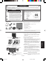
La confezione del nuovo monitor LCD NEC AccuSync* deve
contenere le seguenti parti:
• Monitor LCD AccuSync con base inclinabile
• Cavo audio
• Cavo di alimentazione
• Cavo segnali video
• Manuale Utente
• CD ROM
• Supporto base
*
Conservare la confezione ed il materiale di imballaggio originali
per trasportare o spedire il monitor.
Manuale
Utente
Cavo
audio
Cavo di
alimentazione
Cavo segnali
video
Supporto
base
Monitor LCD AccuSync
(supporto base non
collegato)
Guida rapida
Per collegare la base al supporto LCD:
1. Fissare la base al supporto. Le linguette di bloccaggio sul supporto
devono essere inserite nel foro della base (Figura S.1).
Per collegare il monitor LCD AccuSync al sistema, attenersi alle
seguenti istruzioni:
1. Spegnere il computer.
2. Per il PC con l’uscita analogica: Collegare il cavo segnali con
mini D-SUB a 15 pin al connettore della scheda video del sistema
(Figura A.1). Serrare tutte le viti.
Per Mac: Collegare l’adattatore cavo MultiSync-Macintosh (non
incluso) al computer. Fissare il cavo segnali mini D-SUB a 15 pin
all’adattatore cavo MultiSync Macintosh (Figura A.2). Serrare
tutte le viti.
NOTA: Alcuni sistemi Macintosh non dispongono di un adattatore
cavo Macintosh.
3. Collegare il mini D-SUB a 15 pin del cavo segnali video e il cavo
Audio al connettore appropriato sulla parte posteriore del monitor
(Figura B.1). Collegare le cuffie (non incluse) al connettore
appropriato sulla sinistra del monitor (Figura C.1).
4. Collegare un’estremità del cavo di alimentazione al monitor e
l’altra estremità alla presa di alimentazione. Collocare il cavo
segnali video e il cavo di alimentazione sul supporto cavi
(Figura B.1).
NOTA: Regolare la posizione del cavo posizionato sul supporto
cavi per evitare danni al cavo stesso o al monitor.
NOTA: Fare riferimento alla sezione “Attenzione” di questo
manuale per una scelta corretta del cavo di alimentazione.
ATTENZIONE
CD ROM
Figura S.1
Base
Linguette di bloccaggio
Supporto
Figura A.1 Figura A.2
Adattatore cavo
Macintosh (non incluso)
Figura B.1
Supporto cavi
Ingresso audio
Input (D-Sub)
Collegare all’uscita
audio del computer
Cavo di alimentazione
Manuale
Utente
05_Italian 16/11/07, 11:03 AM1

Italiano-2
Italiano
Linguette di bloccaggio
Controlli
I tasti di controllo OSD (On-Screen Display) sulla parte anteriore del monitor hanno le seguenti funzioni:
1. Funzioni principali tasti
Visualizzazione OSD. Collegamento alla finestra di
regolazione luminosità.
Visualizzazione OSD
nulla
Collegamento alla finestra di
regolazione del volume.
Visualizzazione OSD
(fase di selezione icone)
Si passa allo fase di
regolazione.
Il cursore va a sinistra. Il cursore va a destra.
Visualizzazione OSD
(fase di regolazione)
Si passa allo fase di
selezione icone.
Diminuzione valore
regolazione oppure il
cursore va a sinistra per
effettuare la regolazione.
Aumento valore di
regolazione oppure il
cursore per la regolazione
va a destra.
SELECT
– +
Si mette in funzione la
“regolazione automatica”.
Operazione di Reset.
Commutatore mute off/on
nella finestra di regolazione
volume.
AUTO/RESET
Pulsante
CUFFIE
Figura C.1
Pulsante di alimentazione
Figura TS.1
Figura R.1
Superficie non abrasiva
Figura R.2
Figura R.3
4 VITI (M4)
(profondità MAX: 10 mm)
Se si utilizza un’altra vite,
verificare la profondità del
foro.
Peso del gruppo LCD: 4,8 kg (MAX)
Specifiche tecniche
Serrare tutte le viti
100 mm
Spessore della staffa
(braccio) 2,0 ~ 3,2 mm
4 x 12 mm con rondella di
bloccaggio e rondella piatta
M4
12 mm
100 mm
5. Accendere il monitor con il pulsante di alimentazione inferiore e il
computer (Figura C.1).
6. La regolazione automatica No-touch regola automaticamente il
monitor sulle impostazioni ottimali al momento della
configurazione iniziale per la maggior parte delle temporizzazioni.
Per ulteriori regolazioni, usare i seguenti controlli OSD:
• Regolazione automatica del contrasto
• Auto Aggiust
Fare riferimento alla sezione Controlli di questo Manuale Utente
per una descrizione completa di questi controlli OSD.
NOTA: In caso di problemi, fare riferimento alla sezione Ricerca
guasti (CD-ROM).
Inclinazione
Afferrare con le mani i due lati dello schermo del monitor e inclinarlo
a piacere (Figura TS.1).
Rimozione del supporto monitor per il montaggio
Per predisporre il monitor a un diverso montaggio:
1. Scollegare tutti i cavi.
2. Sistemare il monitor verso il basso su una superficie non abrasiva
(Figura R.1).
3. Togliere le 2 viti che fissano il monitor al supporto e sollevare il
supporto come illustrato (Figura R.2).
Il monitor ora è pronto per essere montato in modo diverso.
4. Collegare il cavo di alimentazione AC ed il cavo segnali al retro
del monitor (Figura R.3).
5. Per rimontare sul supporto, ripetere queste operazioni nell’ordine
inverso.
NOTA: Utilizzare esclusivamente un metodo di montaggio
alternativo compatibile VESA.
NOTA: Rimuovere con cautela il supporto del monitor.
Rimozione della base
NOTA: Rimuovere sempre la base quando si sposta l’LCD.
1. Sistemare il monitor verso il basso su una
superficie non abrasiva (Figura R.1).
2. Con le dita premere contemporaneamente le
3 linguette di bloccaggio sul lato destro e
sinistro per sbloccare la base.
3. Con le dita premere
contemporaneamente le 3 linguette di bloccaggio
sull’altro lato per sbloccare la base.
4. Tirare per sbloccare la base.
Collegamento di un braccio flessibile
Il monitor LCD è progettato per essere utilizzato con il braccio
flessibile.
Durante l’installazione utilizzare le viti (4 pezzi) come indicato nella
figura. Secondo le norme di sicurezza, il monitor deve essere
montato ad un braccio in grado di garantire la stabilità necessaria in
base al peso del monitor.
Il monitor LCD deve essere utilizzato esclusivamente con un braccio
di tipo approvato (per es. marca GS).
05_Italian 16/11/07, 11:03 AM2

Italiano-3
Italiano
AUDIO
Controlla il volume degli altoparlanti o delle cuffie. Per disattivare
l’uscita degli altoparlanti, premere il pulsante “AUTO/RESET”.
LUMINOSITÀ
Regola la luminosità dell’immagine e dello schermo.
Per attivare la MODALITÀ ECO, premere il pulsante “AUTO/
RESET”.
CONTRASTO
Regola la luminosità dell’immagine in relazione allo sfondo.
AUTO-CONTRASTO
Regola l’immagine visualizzata per input video non standard.
REGOLAZIONE AUTOM.
Regola automaticamente la posizione immagine, la
dimensione orizzontale e la regolazione di precisione.
SIN./DEST.
Controlla la posizione orizzontale dell’immagine all’interno
dell’area di visualizzazione dell’LCD.
GIÙ/SU
Controlla la posizione verticale dell’immagine all’interno
dell’area di visualizzazione dell’LCD.
DIMENSIONE ORIZZ.
Regola la dimensione orizzontale aumentando o diminuendo
questa impostazione.
FINE
Migliora messa a fuoco, nitidezza e stabilità dell’immagine,
aumentando o diminuendo questa impostazione.
SISTEMI DI CONTROLLO COLORE
L’impostazione di colore desiderata può essere selezionata
tra cinque impostazioni predefinite di colore (9300/7500/
sRGB/UTENTE/NATIVO).
COLORE ROSSO
Aumenta o diminuisce il rosso. La modifica comparirà sullo
schermata.
COLORE VERDE
Aumenta o diminuisce il verde. La modifica comparirà sullo
schermata.
COLORE BLU
Aumenta o diminuisce il blu. La modifica comparirà sullo schermata.
STRUMENTO
Selezionando STRUMENTO è possibile ottenere il sottomenu.
CONFIG. DI FABBRICA
Selezionando Config. di fabbrica è possibile resettare tutte le
impostazioni dei controlli OSD riportandole alle configurazioni di
fabbrica. Il pulsante RESET deve essere tenuto premuto per
diversi secondi per avere effetto. È possibile resettare
impostazioni individuali selezionando il relativo comando e
premendo il pulsante RESET.
EXIT
Selezionando EXIT è possibile uscire dal menu/sottomenu OSD.
LINGUA
I menu di controllo OSD sono disponibili in nove lingue.
DISABILITAZIONE OSD
Il menu di controllo OSD rimane attivo per il tempo che è in
uso. Nel sottomenu Disabilitazione OSD, è possibile
selezionare l’intervallo di tempo dopo il quale, nel caso non
venga premuto nessun tasto, il menu di controllo OSD si
chiude. Le scelte preimpostate sono 10 - 120 secondi
intervallati da 5 secondi.
BLOCCO OSD
Questo comando blocca l’accesso a tutte le funzioni di
comando OSD ad eccezione di Luminosità e Contrasto. Se si
tenta di attivare i controlli OSD in modalità Blocco OSD ,
apparirà una schermata che informa del fatto che i controlli
OSD sono bloccati. Per attivare la funzione Blocco OSD,
premere il tasto “AUTO/ RESET”, quindi il tasto “+” e tenerli
premuti contemporaneamente. Per disattivare la funzione
Blocco OSD, premere il tasto “AUTO/ RESET”, quindi il tasto
“+” e tenerli premuti contemporaneamente.
ESPANSIONE
Seleziona la modalità zoom.
INTERO: L’immagine viene espansa a 1680 x 1050,
indipendentemente dalla risoluzione.
PROP.: L’immagine viene espansa senza cambiare il rapporto
proporzionale.
DDC/CI
ATTIVA o DISATTIVA la comunicazione bidirezionale e il
controllo del monitor.
NOTIF. MODALITÀ ECO
Se è selezionato ON, dopo l’accensione sullo schermo
appare un messaggio che avvisa che la MODALITÀ ECO è
attivata o disattivata.
MONITOR INFO
Indica il modello e i numeri di serie del monitor.
Avvertenza OSD
I menu di avvertenza OSD scompaiono quando si preme il
pulsante SELECT.
NESSUN SEGNALE: Questa funzione avverte in caso non vi
sia nessun segnale presente. Dopo l’accensione o quando vi
è un cambiamento del segnale di input o il video è inattivo,
apparirà la finestra Nessun Segnale.
FUORI PORTATA: Questa funzione suggerisce la risoluzione
e la frequenza di rinfresco ottimali. Dopo aver attivato
l’alimentazione, in caso di modifica del segnale di ingresso o
se il segnale video non ha una temporizzazione adatta,
apparirà il menu Fuori tolleranza.
2. Struttura OSD
Sottomenu
(icona Seleziona)
Sottomenu (Regolazione)
Premere il tasto “SELEZIONA”
Strumento di esempio:
Premere il tasto “SELEZIONA”
Premere il tasto “SELEZIONA”
Regolazione
utilizzando “–” o “+”
Premere
“–” o “+”
Premere
“–” o “+”
Menu principale
(icona Seleziona)
Menu principale
(Regolazione)
Premere il tasto “SELEZIONA”
Regolazione
utilizzando “–” o “+”
Premere
il tasto
“SELEZIONA”
Premere
il tasto
“SELEZIONA”
05_Italian 16/11/07, 11:03 AM3

Русский-1
Русский
Заявление изготовителя
Настоящим подтверждаем, что цветной ЖК-монитор AccuSync
LCD224WM (L227HK) соответствует
Директиве Совета 73/23/EEC:
– EN 60950-1
Директиве Совета 89/336/EEC:
– EN 55022
– EN 61000-3-2
– EN 61000-3-3
– EN 55024
ОПАСНОСТЬ ПОРАЖЕНИЯ ЭЛЕКТРИЧЕСКИМ ТОКОМ • НЕ ОТКРЫВАТЬ
ВО ИЗБЕЖАНИЕ ВОЗГОРАНИЯ ИЛИ ПОРАЖЕНИЯ ЭЛЕКТРИЧЕСКИМ ТОКОМ НЕ ПОДВЕРГАЙТЕ АППАРАТ ВОЗДЕЙСТВИЮ ДОЖДЯ ИЛИ
ВЛАГИ. КРОМЕ ТОГО, НЕ ВСТАВЛЯЙТЕ ПОЛЯРНУЮ ВИЛКУ УСТРОЙСТВА В РОЗЕТКУ УДЛИНИТЕЛЯ ИЛИ ДРУГИЕ РОЗЕТКИ, ЕСЛИ ЕЕ
ШТЫРЬКИ НЕ ВХОДЯТ ПОЛНОСТЬЮ.
НЕ ОТКРЫВАЙТЕ КОРПУС, ТАК КАК ВНУТРИ НАХОДЯТСЯ ДЕТАЛИ ПОД ВЫСОКИМ НАПРЯЖЕНИЕМ. ПО ВОПРОСАМ ОБСЛУЖИВАНИЯ
ОБРАТИТЕСЬ К КВАЛИФИЦИРОВАННОМУ СПЕЦИАЛИСТУ.
ПРЕДУПРЕЖДЕНИЕ
ВНИМАНИЕ. ЧТОБЫ УМЕНЬШИТЬ РИСК ПОРАЖЕНИЯ
ЭЛЕКТРИЧЕСКИМ ТОКОМ, НЕ СНИМАЙТЕ КРЫШКУ (ИЛИ
ЗАДНЮЮ ПАНЕЛЬ). ВНУТРИ АППАРАТА НЕТ ДЕТАЛЕЙ,
ОБСЛУЖИВАНИЕ КОТОРЫХ МОЖЕТ ВЫПОЛНЯТЬ
ПОЛЬЗОВАТЕЛЬ. ПО ВОПРОСАМ ОБСЛУЖИВАНИЯ
ОБРАТИТЕСЬ К КВАЛИФИЦИРОВАННОМУ СПЕЦИАЛИСТУ.
Этот знак предупреждает пользователей о том, что внутри
устройства находятся неизолированные детали под высоким
напряжением, которые могут стать причиной поражения
электрическим током. Поэтому ни в коем случае нельзя
прикасаться к каким-либо деталям внутри устройства.
Этот знак предупреждает пользователей о том, что имеется
важная документация по эксплуатации и обслуживанию
этого устройства. Поэтому ее необходимо внимательно
прочитать, чтобы избежать возможных проблем.
ВНИМАНИЕ
и содержит отметку
NEC Display Solutions, Ltd.
4-13-23, Shibaura,
Minato-Ku
To kyo 108-0023, Japan
Содержимое
В упаковочной коробке* нового монитора NEC AccuSync LCD
должно быть следующее:
• Монитор AccuSync LCD с шарнирной опорой
• Кабель аудиосигнала
• Кабель питания
• Кабель видеосигнала
• Руководство пользователя
• диск CD-ROM
•Подставка основания
* Обязательно сохраните коробку и упаковочный материал для
транспортировки или перевозки монитора.
Руководство
пользователя
Кабель
аудиосигнала
Кабель
питания
Кабель
видеосигнала
Подставка
основания
Монитор AccuSync LCD
(подставка основания не
подсоединена)
Краткое руководство по началу работы
Чтобы подсоединить основание к подставке ЖКД:
1. Закрепите подставку на основании. Защелки на подставке
должны войти в соответствующее отверстие основания
(Рисунок S.1).
Чтобы подключить ЖКД монитор AccuSync LCD к системе,
выполните следующие инструкции:
1. Отключите питание компьютера.
2.
Для ПК с аналоговым выходом: Подсоедините 15-штырьковый
мини-разъем D-SUB кабеля видеосигнала к разъему платы
видеоадаптера в компьютере (Рисунок A.1). Затяните все винты.
Для Mac: Подсоедините адаптер кабеля для MultiSync
Macintosh (не входит в комплект) к компьютеру. Подключите
кабель видеосигнала с 15-штырьковым мини-разъемом D-SUB
к адаптеру кабеля для MultiSync Macintosh (Рисунок A.2).
Затяните все винты.
ПРИМЕЧАНИЕ. Для некоторых компьютеров Macintosh адаптер
кабеля Macintosh не требуется.
3. Подключите 15-штырьковый миниразъем D-SUB видеокабеля
и аудиокабель к соответствующим разъемам на задней
панели монитора (Рисунок B.1). Подключите наушники (не
входят в комплект) к соответствующему разъему на левой
панели монитора (Рисунок С.1).
4. Подключите один конец кабеля питания к монитору,
а другой — к розетке электропитания. Поместите кабель
видеосигнала и кабель питания в держатель (Рисунок B.1).
ПРИМЕЧАНИЕ. Отрегулируйте положение кабеля в держателе
таким образом, чтобы предотвратить
повреждение кабеля или монитора.
ПРИМЕЧАНИЕ. Рекомендации по правильному выбору кабеля
питания см. в разделе “Внимание” настоящего
руководства.
ME06
CD-ROM
Рисунок S.1
Основание
Фиксирующие
выступы
Подставка
Рисунок A.1 Рисунок A.2
Адаптер кабеля для
Macintosh (не входит
в комплект)
Рисунок B.1
Держатель кабелей
Аудиовход
Вход (D-Sub)
Подключите к
аудиовыходу компьютера
Кабель питания
Руководство
пользователя
06_Russian 16/11/07, 11:03 AM1
La pagina sta caricando ...
La pagina sta caricando ...
La pagina sta caricando ...
La pagina sta caricando ...
La pagina sta caricando ...
La pagina sta caricando ...
-
 1
1
-
 2
2
-
 3
3
-
 4
4
-
 5
5
-
 6
6
-
 7
7
-
 8
8
-
 9
9
-
 10
10
-
 11
11
-
 12
12
-
 13
13
-
 14
14
-
 15
15
-
 16
16
-
 17
17
-
 18
18
-
 19
19
-
 20
20
-
 21
21
-
 22
22
-
 23
23
-
 24
24
-
 25
25
-
 26
26


NEC AccuSync® LCD224WM Manuale del proprietario
- Categoria
- TV
- Tipo
- Manuale del proprietario
in altre lingue
Documenti correlati
-
NEC ACCUSYNC LCD73V Manuale utente
-
NEC MultiSync® LCD190V Manuale del proprietario
-
-
NEC AccuSync® LCD51VM Manuale utente
-
-
-
NEC MultiSync E271N Manuale del proprietario
-
NEC LCD205WXM, LCD225WXM Manuale utente
-
-
NEC AccuSync® LCD24WMCX Manuale del proprietario