CAME BXE Manuale del proprietario
- Categoria
- Gate Opener
- Tipo
- Manuale del proprietario

Documentazione
Tecnica
S20
rev. 2.1
08/2001
©
CAME
CANCELLI
AUTOMATICI
119BS20
SERIE BX |
BX SERIES
|
SÉRIE BX |
BAUREIHE BX
|
SERIE BX
BXE
CANCELLI AUTOMATICI
Automazioni per cancelli scorrevoli
Automation systems for sliding gates
Automatisations pour portails coulissant
Antriebe für den Schiebetore
Automatización para puertas correderas
3 x 1.5 / 230V
2 x 1 - TX
2 x 1
2 x 1.5
RG58
6
5
9
3
1
2
8
10
4 x 1 - RX
11
3 x 1.5 / 230V
2 x 1 - TX
3 x 1
2 x 1.5
RG58
6
5
4
8
3
1
2
9
9
2 x 1 - TX
4 x 1 - RX
10
4 x 1 - RX
7
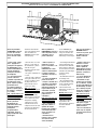
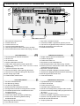
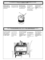
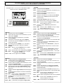
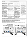
1 - Gruppo BXE
2 - Quadro comando
incorporato
3 - Ricevitore radio
4 - Cremagliera
5 - Selettore a chiave
6 - Lampeggiatore di
movimento
7 - Antenna
8 - Fotocellule di
sicurezza
9 - Colonnina per
fotocellula
10 - Fermo anta
1 - BXE Antriebsmotor
2 - Schalttafel im Antrieb
3 - Funkempfänger
4 - Zahnstange
5 - Außenantenne
6 - Blinkleuchte “Tor in
Bewegung”
7 - Schlüsselschalter
8 - IR Lichtschranke
9 - Lichtschrankeensäule
10 -Toranschlag
1 - BXE unit
2 - Control panel
(incorporated)
3 - Radio receiver
4 - Rack
5 - Electric lock
6 - Flashing light indica-
ting door movement
7 - Antenna
8 - Safety photocells
9 - Photocell column
10 - Closure stop
Impianto tipo Installation type
Standard montage
Instalación tipo
1 - Conjunto BXE
2 - Cuadro de mando
incorporado
3 - Radiorreceptor
4 - Cremallera
5 - Selector mediante
llave
6 - Lámpara intermiten-
te de movimiento
7 - Antena receptora
8 - Fotocélulas de
seguridad
9 - Columna para
fotocélula
10 - Tope puerta
1 - Groupe BXE
2 - Armoire de
commande
incorporé
3 - Récepteur radio
4 - Crémaillère
5 - Sélecteur a clé
6 - Clignotant de
mouvement
7 - Antenne de
réception
8 - Photocellules de
sécurité
9 - Colonne pour
photocellule
10 - Butée d'arrêt
Standard installation

2
CARATTERISTICHE GENERALI -
GENERAL SPECIFICATIONS
- CARACTÉRISTIQUES GÉNÉRALES
ALLGEMEINES MERKMALE
- CARACTERÍSTICAS GENERALES
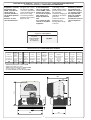
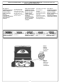
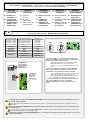
MISURE D'INGOMBRO -
OVERALL DIMENSIONS
- MESURES D'ENCOMBREMENT -
ABMESSUNGEN
- MEDIDAS
Progettato e costruito
interamente dalla
CAME, risponde alle
vigenti norme di
sicurezza (UNI 8612),
con grado di protezio-
ne IP54.
Garantito 12 mesi
salvo manomissioni.
Il a été entièrement
conçu et realisé par
les Ets CAME, confor-
mément aux normes
de sécurité en vigueur
(NFP 25362) avec
degré de protection
IP54.
Il est garanti 12 mois
sauf en cas d'endom-
magement.
Designed and construc-
ted entirely by CAME;
conforms to (UNI 8612)
safety standards with IP
54 protection rating.
12 mounth guarantee;
guarantee void if unit is
tampered with.
Vollständig von der
CAME geplant und her-
gestellt, entsprechend
den geltenden
Sicherheits-bedigungen
(UNI 8612) mit Schutz-
grad IP54.
12 Monate Garantie,
Bedienungs und
Montagefehler ausge-
schlossen.
Diseñado y construi-
do totalmente por
CAME, con arreglo a
las vigentes normas
de seguridad (UNI
8612) con grado de
protección IP54.
Garantia de 12 meses
salvo manipulacio-
nes.
CARATTERISTICHE TECNICHE -
TECHNICAL CHARACTERISTICS -
CARACTERISTIQUES TECHNIQUES
TECNISCHE DATEN -
CARACTERISTICAS TECNICAS
240
105
150
290
125165
105
310
22 max.
-amissamatatroP
-stimilesU
xameétroP
-thciwegroT
atreuposeP
elaiznediserosu
laitnediseR
leitnediseregasu
ztasnienetavirp
laicnediserosu
008gK
MOTORIDUTTORE
GRADO DI
PROTEZIONE
PESO ALI MENTA ZIONE ASSORBIMENTO POTENZA
INTERMITTENZA
LAVORO
COPPIA RAPPORTO DI RI DU ZIONE SPI NTA VELOCITA ' MA X. CONDENSATORE
GEARMOTOR
PROTECTION
RATING
WEIGHT POWER SUPPLY CUR RENT POWER DUTY CICLE MAX TOR QUE
RED UCTION
RATIO
PUSH MAX. SPEED CAPACITOR
MOTOR ÉDUCTEUR
DEGRÉ DE
PROTECTION
POIDS ALI MENTATI ON ABSORPTI ON PUISSANCE
INTERMIT TENCE
DE TRAVAIL
COUPLE RAPPOR T DE REDUC TION POUSSÉE VITESSE MAX. CONDENSATEUR
GET RI EBEMOTOR SCHUTZGRAD GEWI CH T
STROM_
VERSORGU NG
STROMAUF NAHME LEI STUNG EINSCHALTDAUER DREHMOMEN T
UNTERSET ZUNGS_
VERHÄLTN IS
REGELBARER
MAX.
ÜBERTRAGU NGS
KONDENSATOR
MOTORREDUCTOR
GRADO DE
PROTECCION
PESO ALIM ENTACI ON ABSORBENCIA POTENCIA
INTERMITENCIA
TRA BAJO
PAR E JA
(MOTOR)
RELACION DE
RED UCCION
EMPUJE
VELOCIDAD
MAX.
CONDEN SADOR
BXE IP 54 15 Kg 230V a.c. 2,4A 300W 30 % * 32 Nm 1/33 800 N 10 m/min. 20 µF
* Ottenuta mediante quadro comando CAME
* Obtained with CAME control panel
* Obtenue au moyen armoire de commande CAME
* Erreicht mit Hilte der "CAME" Schalttafel
* Se obtiene mediante el cuadro de mando CAME

3
PRIMA DELL'INSTALLAZIONE ... -
BEFORE INSTALLING .....
- AVANT D'INSTALLER L'AUTOMATISME .....
VOR DEN INSTALLATION ÜBERPRÜFEN
... - ANTES DE INSTALAR EL AUTOMATISMO...
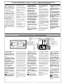
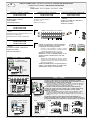
FISSAGGIO BASE MOTORE -
MOTOR TO BASE ANCHORAGE
- FIXATION DE LA PLAQUE DU MOTEUR
BEFESTIGUNGS DER MOTORBASIS
- FIJACIÓN BASE MOTOR
- La hoja de la puerta debe
estar suficientemente rigida
y compacta
- Las ruedas de desliza-
miento deben estar perfecta
y engrasadas adecuada-
mente.
- La guia de deslizamiento
debe estar bien fijada en el
suelo, sobresaliendo a lo
largo de su entera longitud,
sin huecos ni irregularida-
des (que podrian
obstaculizar el movimiento
de la puerta).
- La guia superior debe
tener el justo juego con la
puerta metálica (para ga-
rantizar un movimiento
regular y silencioso).
- Disponer un tope para
apertura y el cierre.
- Disponer un conducto
para los cables eléctricos
que cumpla con las disposi-
ciones de mando y
seguridad.
- Die Leistungfähigkeit der
feststehenden und bewegli-
chen Teile des Tores
überprüfen.
- Das Tor sollte ausreichend
stabil sein. Die Gleitrollen
sollten in guten Zustand und
angemessen geschmiert sein.
- Die Gleitführung auf dem
Boden sollte sich in optimaler
Position befinden: gut auf
dem Boden befestigt, in sei-
ner Gesamtlänge vollständig
über dem Boden, ohne Ver-
tiefungen und/oder
Unebenheiten, die die Tor-
bewegung behindern können.
- Die oberen Führungsschie-
nen sollten das richtige Spiel
zum Tor haben, um ein präzi-
ses und regelmäßiges Gleiten
zu garantieren.
- Einen Anschlag für Tor Auf
und Tor Tu sollte vorhanden
sein.
- Den Lauf der elektrischen
Kabel nach den Steuerungs
und Sicherheitsbestim-
mungen vorsehen.
- Le panneau mobile du
portail devra être suf-
fisamment rigide et solide.
- Les roues de coulis-
sement devront être en très
bon état. En outre, elles
devront être conve-
nablement graissées.
- Le rail de guidage devra
être bien fixé au sol. De
plus, il devra se présenter
entièrement en surface sans
affaissement ou irrégularité
(qui pourraient empêcher le
mouvement du portail).
- Le guide supérieur devra
avoir un jeu convenable
avec le portail (pour per-
mettre un mouvement
régulier et silencieux).
- Prévoir une butée d’arrêt à
l’ouverture et à la ferme-
ture.
- Prévoir le passage des
câbles électriques selon les
dispositifs de commande et
de sécurité.
- The gate must be suffi-
ciently rigid and solid.
- The wheels on which the
gate slide must be in perfect
condition and adequately
lubricated.
- The wheel guide must be
firmly attached to the
ground, completely expo-
sed, and without any dips or
irregular sections which
might hinder the movement
of the gate.
- The upper guide must allow
for the correct amount of
play in order to guarantee
smooth and silent movement
of the gate.
- Opening and closure stops
must be installed.
- The wiring must be routed
as specified by the control
and safety requirements.
- Controllare che l'anta sia
rigida e compatta e che le
ruote di scorrimento siano
in buono stato e adeguata-
mente ingrassate.
- La guida a terra dovrà es-
sere ben fissata al suolo,
completamente in superficie
in tutta la sua lunghezza e
priva di irregolarità che
possano ostacolare il movi-
mento del cancello.
- I pattini-guida superiori
non devono creare attriti.
- Prevedere un fermo anta
in apertura e uno in chiusu-
ra ed il percorso dei cavi
elettrici come da impianto
tipo.
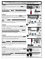
- Inserire le viti nella pia-
stra di ancoraggio
bloccandole con i dadi in
dotazione, ed estrarre le
zanche preformate verso il
basso.
- Predisporre, dimensio-
nandola in base alle misure
del motoriduttore, una piaz-
zola in cemento (si
consiglia di farla sporgere
dal terreno di circa 50 mm.)
con annegata la piastra di
ancoraggio e relative
zanche sulla quale sara'
fissato il gruppo.
- La base di fissaggio dovra'
risultare perfettamente in
bolla, pulita in tutte le sue
estremita', con il filetto
delle viti completamente in
superfice.
N.B.: Dalla stessa dovranno
emergere i tubi flessibili
per il passaggio dei cavi di
collegamento elettrico.
- Install the screws in the
anchor plate and fasten them
with a nut, then bend the pre-
formed clamps downwards.
- Construct a cement founda-
tion that is large enough to
accomodate the gear motor
(it is a good idea to protrude
50 mm. from the ground).
When pouring the founda-
tion, embed the gear motor
anchor plate and the relative
clamps in the cement.
- The anchor bolts should be
embedded in the concrete in
the positions indicated;
the drive unit is then attached
to this bots. The anchor plate
must be perfectly level and
absolu-tly clean; the bolts
threads must be completly
exposed.
N.B.: The flexible tubes for
the electrical wiring must be
embedded in the base and
protude in the correct posi-
tion.
- Introduire les vis dans la
plaque d'ancrage en les
bloquant avec un écrou, et
replier les agrafes préfor-
mées ver le bas.
- Préparer une base en
ciment d'une dimension
adéquate aux mesures du
motoréducteur (il est con-
seillé de la faire dépasser
du terrain d'environ 50
mm.), et noyer dedans la
plaque d'ancrage et les
agrafes correspondantes
afin de permettre le fixage
du groupe.
- La base de fixation devrà
être parfaitement de niveau
et propre sur toute sa
surface et le filet des vis
devra être complètement en
surface.
N.B. Les câbles pour le
branchement électrique
devront sortir de cette base.
- Die Schrauben in die Anker-
platte einfügen und mit einer
Schraubenmutter blockieren,
die vorgeformten Fundament-
anker nach unten umbiegen.
- Eine den Abmessungen des
Getriebemotors entsprechen-
de Betonfundamentplatte (Es
empfiehlt sich, diese ca. 50
mm. vom Boden herausragen
zu las-sen) zum Einbetten der
Ankerplatte und der entspre-
chenden Fundamentanker,
die zur Befestigung des An-
triebsaggregats dienen,
vorbereiten.
- Die Befestigungs-unterlage
muß in seiner gesamten Län-
ge vollkommen eben und
sauber sein. Das Gewinde der
Schrauben müssen gänzlich.
hervorstehen.
Wichtig: die Kabel für den
Elektroanschluß müssen
herausrgen.
- Introducir los tornillos en
la placa de anclaje, blo-
queándolos con una tuerca,
y doblar las palancas
preformadas hacia abajo.
- Preparar, dándole las di-
mensiones adecuadas en
función de las medidas del
motorreductor, una platafor-
ma de cemento (se
aconseja dejarla sobresalir
del suelo aprox. 50 mm.)
con la placa de enclaje
embedida y con las corres-
pondientes varillas, que
permitrá la fijación del gru-
po.
- La base de fijación debe
estar perfectamente nivela-
da, limpia en todos sus
extremos, con la rosca de
los tornillos totalmente in
superficie.
N.B.: De ésta deben
sobresilar los tubos flexi-
bles para el paso de los
cables para las conexiones
eléctricas.
50 mm.
75 mm.
105 mm.
Struttura fissa
Wall
Structrure fixe
Feste Struktur
Estructura fija
Anta cancello
Gate wing
Panneau mobile du portail
Gleitachse
Puerta
Piazzola in cemento
Concrete base
Plate-forme en ciment
Plattenachse
Plataforma de cemento
Cavi
Cable
Câbles
Kabel
Cables
Cremagliera
Rack-limit
Cremaillére
Zahnstange
Cremallera
Piastra di ancoraggio / Zanche
Fixing plate / Anchor stays
Plaque de fixation / Agrafes
Gleitachse / Verankerung
Placa de fijación / Barras de fijción

4
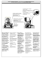
INSTALLAZIONE DEL GRUPPO -
UNIT INSTALLATION -
INSTALATION DU GROUPE
AUFSTELLUNG DES AGGREGATS
- COLOCACIÓN DEL GRUPO
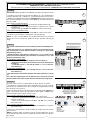
Nella fase preliminare di
installazione, i piedini
dovranno sporgere di 5-
10 mm. per permettere
allineamenti, fissaggio
della cremagliera e
regolazioni successive.
L'accoppiamento esatto
con la linea di scor-
rimento del cancello è
ottenibile dal sistema di
regolazione integrale
(brevettato) composto da:
- le asole che permet-
tono la regolazione
orizzontale;
- i piedini filettati in
acciaio che permettono
la regolazione verticale e
la messa in bolla;
- le piastrine e i dadi di
fissaggio che rendono
solidale l'aggancio del
gruppo alla base.
During the initial phase of
installation, the feet
should protrude by 5-10
mm. in order to allow for
alignment, anchorage of
the rack and further
adjustments.
Perfect alignment with the
guide rail is made possible
by the (patented) built-in
regulation system, which
consists of:
- slots for horizontal
adjustment;
- threaded steel feet for
vertical adjustment and
levelling;
- plates and bolts for
anchorage to the base.
Dans la phase de
instalation préliminaire,
les broches devront
dépasser de 5 à 10 mm
afin de permettre les
alignements et les
réglages nécessaires
après la pose.
L’accouplement exact
avec la ligne de
coulissement du portail
s’effectue par le système
de réglage hauteur
(breveté) dont le groupe
est pourvu, et qui
comprend plus
précisément:
- les trous oblong
permettant le réglage
horizontal;
- les broches filetées en
acier qui donnent le
réglage vertical et la
mise à niveau;
- les plaques et les
écrous de fixation qui
assemblent solidement le
groupe à la plaque de
fixation scellée.
Nun die Montage des
Antriebsmotors vorneh-
men. Die genaue Kop-
plung mit der Gleitlinie des
Tors wird von dem
integrierten Einstel-
lungssystem (patentiert)
garantiert, mit dem das
Aggregat ausgestattet ist
und zwar:
- die Osen für die
horizontale Einstellung,
- die Gewindefüße aus
Stahl für die vertikale
Einstellung und die
Nivellierung,
- die Befestigungsplät-
tchen und muttern zur
soliden Befestigung des
Aggregats an die
Bodenplatte.
Während der Vorberei-
tungsarbeiten der Montage
sollten die Füße 5-10 mm
herausragen, um
Ausfluchtungen und
Einstellung auch nach der
Fertigstellung zu
ermöglich.
En la fase previa de la
colocación, los pies
deben sobresalir 5-10
mm para consentir la
alineación, la fijación de
la cremallera y las regu-
laciones sucesivas.
El acoplamiento exacto
con la linea de desli-
zamiento de la puerta
metálica se obtiene
mediante el sistema de
regulación integral
(patentado) que consta
de:
- los agujeros ovalados
que consienten la
regulación horizontal;
- las tuercas de acero
que permiten la
regulación vertical y la
nivelación;
- las placas y las tuercas
de fijación que hacen
solidario el enganche del
conjunto con la base.
5÷10 mm.
Ingresso cavi
Cable entrances
Passage des câbles
Kabeleinführungen
Accoppiamento pignone-cremagliera
con gioco 1÷2 mm.
Rack-to-pinion coupling with 1÷2 mm. clearance
Assemblage pignon-crémailère avec jeu
de 1 à 2 mm.
Zwischen Zahnstange und dem Antriebsritzel
1÷2 mm. Spiel einstellen
Acoplamiento piñon-cremaliera
1÷2 mm. de juego
Regolazione orizzontale e fissaggio
Horizontal adjustment unit and achorage
Réglage horizontal et fixation
Horizontale Einstellung
Regulación horizontal y fijación
Regolazione verticale - messa in bolla
Vertical adjustment and unit leveling
Réglage vertical - mise à niveau
Vertikale Einstellung
Regulación vertical y nivelación
Entrada cables
1÷2 mm.

5
FISSAGGIO CREMAGLIERA-
ATTACHING THE RACK/LIMIT
- FIXATION CREMAILLÉRE
MONTAGE DE ZAHNSTANGE -
FIJACIÓN DE LA CREMALLERA
Con el fin de permitir al
ENCODER medir la
carrera de la puerta, fijar
la cremallera con el
mismo a mitad de
carrera:
- coloque la hoja en la
mitad de la carrera,
apoye la cremallera
sobre el piñon del
motorreductor y deslice
manualmente la puerta,
fijando la cremallera a
todo lo largo;
- La carrera máxima de
la puerta es de 14 m;
- Finalizadas las ope-
raciones para la fijacion
de la cremallera, regular
los pies (por medio de un
destornillador) de modo
que se obtenga el justo
juego entre el piñón y la
cremallera (1-2 mm).
N.B. Esto hace que el
peso de la puerta
metálica no cargue sobre
el conjunto.
- Si la cremallera ya ha
sido fijada, hay que
regular el acoplamiento
piñón/cremallera.
- Una vez realizados los
ajuste, fijar el conjunto
cerrando las dos tuercas
de fijación.
Ist der ENCODER zur
Erfassung bzw. Überwa-
chung des Torlaufs auf
halber Laufhöhe auf der
Zahnstange zu befestigen:
- den Torflügel halb öffnen
und die Zahnstange auf
dem Ritzel vom Getriebe-
motor auflegen. Dann das
Tor von Hand verschieben
und dabei die Zahnstange
auf ganzer Länge
befestigen;
- Der maximale Lauf vom
Tor beträgt 14 m;
- Die verstellbaren Füße
des Antriebsmotors (mit
einem Schraubenzieher)
so einstellen, daß
zwischen Ritzel und
Zahnstange ein Spiel (1-2
mm) besteht.
Wichtig: Dadurch wird
vermieden, daß das
Gewicht des Tores auf
dem Aggregat lastet.
- Nach diesen Einstel-
lungsarbeiten das
Aggregat durch Anziehen
der beiden Muttem
befestigen.
Afin de permettre à
l'ENCODEUR de relever la
course du portail, fixer la
crémaillère avec le
portail à micourse:
- mettre la porte à la
moitié de sa course,
poser la crémaillère sur
le pignon du
motoréducteur et faire
coulisser manuellement
le portail en fixant la
crémaillère sur toute sa
longueur;
- La course maximum du
portail est de 14 m;
- Lorsque la fixation de la
crémaillère est terminée
régler les broches (en
utilisant un tournevis) de
façon à obtenir un jeu
convenable (1-2 mm)
dans l’assemblage du
pignon et de la
crémaillère.
N.B. Ceci pour éviter que
le poids du portail ne
repose sur le groupe.
- Si la crémaillère est
déjà fixée, utiliser le
système de réglage
hauteur pour assembler
correctement de facon
exacte le pignon et la
crémaillère.
- Exécuter tous les
réglages, fixer le groupe
en serrant les deux
écrous de fixation.
Install the rack with the
gate at the half-way point.
This will enable the
ENCODER to detect gate
travel properly:
- allow the door to reach
mid-run, set the rack on
the rationmotor's pinion
and slide the gate
manually, fixing the rack's
entire lenght;
- The gate's maximum run
is 14 m;
- when the rack is attached
to the gate, adjust the feet
using a screwdriver until
the play between the
pinion and the rack is
correct (1-2 mm.).
N.B.: This position
ensures that the weight of
the gate does not rest on
the gearmotor.
- If the rack is already
attached, proceed directly
to the adjustment of the
rack/pinion coupling.
- When the necessary
adjustment have been
completed, fasten the unit
in position by tightening
the two anchor bolts.
Al fine di permettere
all'ENCODER di rilevare
la corsa del cancello,
fissare la cremagliera
con il cancello a meta'
corsa:
- portare l'anta a meta'
corsa, appoggiare la
cremagliera sul pignone
del motoriduttore e far
scorrere manualmente il
cancello fissando la
cremagliera in tutta la
sua lunghezza;
- La corsa massima del
cancello é di 14 m;
- ultimata l'operazione di
fissaggio della crema-
gliera, regolare i piedini
(servendosi di un
cacciavite) in modo da
ottenere il giusto giuoco
tra pignone e cremaglie-
ra (1-2 mm).
N.B. : Questo evitera' che
il peso del cancello vada
a gravare sul gruppo.
- Se la cremagliera é gia'
fissata, procedere
direttamente alla
regolazione dell'accop-
piamento pignone/
cremagliera.
- Eseguite tutte le
regolazioni, fissare il
gruppo stringendo i dadi
di fissaggio.

6
SBLOCCO MOTORIDUTTORE -
GEAR RELEASE
- OPÉRATION DE DÉBLOCAGE
- ANTRIEBSENTRIEGELUNG
DESBLOQUEO MOTORREDUCTOR
Per aprire lo
sportellino inserire la
chiave, spingerla e
ruotala in senso
orario; sbloccare
quindi il
motoriduttore
ruotando la manopola
nella direzione
indicata.
Pour ouvrir la trappe,
introduire la clé, la
pousser et la tourner
dans le sens des
aiguilles d'une
montre. Débloquer
ensuite le
motoréducteur en
tournant la poignée
dans la direction
indiquée.
Para abrir la
portezuela introducir
la llave, empujarla y
girarla en sentido
horario; desbloqear el
motorreductor
girando la manilla en
la dirección indicada.
To open the access
door, insert the key,
push down and rotate
clockwise. Now, release
the gear motor by
rotating the knob in the
direction shown.
Zum Öffnen der klappe
den Schlüssel
einfügen,
hineindrücken und im
Uhrzeigersinn drehen.
Dann den
Getriebemotor durch
Drehen des Knopfs in
die angegebene
Richtung entsperren.
ATTENZIONE:
l'apertura dello spor-
tellino di sblocco im-
pedisce il funziona-
mento del motore.
ATTENTION:
the opening of the
unblock panel arrests
the motor.
ATTENTION:
l’ouverture de la por-
te de déblocage
empêche le fonction-
nement du moteur.
ACHTUNG:
Wenn das Freigabetür-
chen geöffnet wird,
funktioniert der Motor
nicht.
ATENCIÓN:
la apertura de la tapa
de desbloqueo,
impide el funciona-
miento del motor.
Release
Sblocco
Blocco
Engage
Blockierend
Entriegelt
Blocage
Déblocage
Desbloqueo
Bloqueo
CAME

7
Important:
- the opening of the unblock panel arrests
the motor.
- Shut off the mains power and disconnect
the batteries before servicing the inside
of the unit.
La scheda comando va alimentata a (230V
a.c.) sui morsetti L1 e L2 ed è protetto in
ingresso con fusibili da 5A.
I dispositivi di comando sono a bassa ten-
sione (24V), e sono protetti con fusibile da
1A. La potenza complessiva degli acces-
sori a 24V, non deve superare i 20W.
Il tempo lavoro è fisso a 90 secondi.
SICUREZZA
Le fotocellule possono essere collegate e
predisposte per:
-
Riapertura
in fase di chiusura (2-C1);
-
Stop parziale,
arresto del cancello se in
movimento con conseguente pre-
disposizione alla chiusura automatica
(2-C3);
-
Stop totale,
(1-2) arresta il cancello esclu-
dendo l'eventuale ciclo di chiusura
automatica; per riprendere il movimento
bisogna agire sulla pulsantiera o sul
radiocomando;
Nota: Se un contatto di sicurezza normal-
mente chiuso (2-C1, 2-C3, 1-2) si apre,
viene segnalato dal lampeggio del LED di
segnalazione (n°5)
-
Rilevazione di presenza ostacolo.
A mo-
tore fermo (cancello chiuso, aperto o dopo
un comando di stop totale), impedisce
qualsiasi movimento se i dispositivi di si-
curezza (es.fotocellule) rilevano un
ostacolo.
- La scheda, inoltre, integra e gestisce
automaticamente una funzione di sicurez-
za che, in caso di rilevazione di ostacoli,
funziona nel seguente modo:
in apertura
il cancello si ferma e attiva la chiusura
automatica;
in chiusura
il cancello inverte il senso di marcia fino
alla completa apertura con conseguente
intervento della chiusura automatica.
Attenzione! dopo tre inversioni consecuti-
ve, il cancello resta aperto escludendo la
chiusura automatica: per chiudere, usare
il radiocomando o il pulsante di chiusura.
ACCESSORI COLLEGABILI
-
Lampada ciclo.
Lampada che illumina la
zona di manovra, rimane accesa dal mo-
mento in cui l'anta inizia l'apertura fino alla
completa chiusura (compreso il tempo di
chiusura automatica). La funzione della
lampada ciclo si ottiene in uscita W-E solo
se i dip n°1 «chiusura automatica» e n°10
«lampada ciclo» sono posizionati in ON,
vedi pagina 17;
-
Lampada spia cancello aperto.
Lampada
che segnala la posizione di apertura del
cancello e che si spegne quando il cancel-
lo attiva il finecorsa chiude; collegarla ai
morsetti 10-5.
Nota: gli accessori a 24V non necessitano
di collegamento a terra.
ALTRE FUNZIONI
-
Chiusura automatica.
Il temporizzatore di
chiusura automatica si autoalimenta a
finecorsa in apertura. Il tempo prefissato
regolabile, é comunque subordinato dal-
l'intervento di eventuali accessori di
sicurezza e si esclude dopo un intervento
Attenzione:
- l'apertura dello sportellino di sblocco
impedisce il funzionamento del motore.
- prima di intervenire all'interno dell'appa-
recchiatura, togliere la tensione di linea e
scollegare le batterie (se inserite).
DESCRIZIONE TECNICA SCHEDA BASE ZBXE
ITALIANO
di «stop» totale o in mancanza di energia
elettrica;
-
Apertura parziale.
Apertura del cancello
per passaggio pedonale, viene attivata
collegandosi ai morsetti 2-3P ed è
regolabile mediante trimmer AP.PARZ.;
-
Funzionamento a uomo presente.
Fun-
zionamento del cancello mantenendo
premuto il pulsante (selezionandolo si
esclude la funzione del radiocomando);
-
Programmazione
taratura dei finecorsa
elettronici di apertura e di chiusura;
-
Funzione master,
il quadro assume tutte
le funzioni di comando nel caso di due
motori abbinati (vedi pagina 15);
-
Funzione slave
; il quadro viene esclusi-
vamente pilotato dal "master" (vedi pagina
15);
-
Prelampeggio
in apertura e chiusura;
-
Tipo di comando:
- apre-chiude-inversione;
- apre-stop-chiude-stop;
- solo apertura.
REGOLAZIONI
- Trimmer AP.PARZ. = Apertura parziale:
da 1"a 14";
- Trimmer TCA = Tempo chiusura automa-
tica: da 1" a 150";
This control board is powered by 230V
AC across terminals L1 and L2, and is
protected by a 5A fuse on the main power
line. Control systems are powered by low
voltage and protected with by a 1A fuse.
The total power consumption of 24 V ac-
cessories must not exceed 20 W.
Fixed operating time of 90 seconds.
SAFETY
Photocells can be connected to obtain:
-
Re-opening
during the closing cycle (2-
C1);
-
Partial stop,
shutdown of moving gate,
with activation of an automatic closing
cycle (2-C3);
-
Total stop,
(1-2) shutdown of gate move-
ment without automatic closing; a
pushbutton or radio remote control must
be actuated to resume movement;
Note: If a safety contact which is normally
closed (2-C1, 2-C3, 1-2) is opened, the
LED (n°11) will flash to indicate this fact;
-
Obstacle presence detection.
When the
motor is stopped (gate is closed, open or
half-open after an emercency stop com-
mand), the transmitter and the control
pushbutton will be deactivated if an ob-
stacle is detected by one of the safety
devices (for example, the photocells).
- In addition, the board automatically inte-
grates and runs a safety function that
works in the following manner in case
obstacles are detected;
during opening
the gate stops and the automatic closure is
activated;
during closure
the gate inverts its direction until it is com-
pletely open, after which it closes
automatically.
Warning! after three consecutive inver-
sions, the gate will remain open and
automatic closure will be discontinued.
Toclose the gate, use the radio remote
control or the push-button.
ACCESSORIES WHICH CAN BE CON-
NECTED
-
Cycle lamp.
The lamp which lights the
manoeuvring zone: it remains lit from the
moment the gate begin to open until it is
completely closed (including the time re-
quired for the automatic closure). The
function of the cycle lamp is obtained in
output W-E1 only if dip switch No.1 «auto-
matic closing» and No. 10 «Cycle lamp»
are set to ON (see page 17).
-
Open gate pilot lamp.
It is a light that indi-
cates the sliding gate's open position and
turns off when the gate activates the clos-
ing end-stop, connect it to terminal blocks
10-5.
N.B.: the 24V accessories do not need a
earth connection.
OTHER FUNCTIONS
-
Automatic closing
. The automatic clos-
ing timer is automatically activated at the
end of the opening cycle. The preset, ad-
justable automatic closing time is
automatically interrupted by the activation
of any safety system, and is deactivated
after a STOP command or in case of power
failure;
-
Partial opening.
Gate opening for pas-
sage on foot is activated by connecting to
the 2-3P terminal blocks and it can be
adjusted by the AP.PARZ. trimmer;
-
"Operator present"
function: Gate oper-
ates only when the pushbutton is held
down (radio remote control is deactivated
when function is selected);
-
Programming
the calibration of the elec-
tronic opening and closing limit switches;
-
Master function;
the panel assumes all
the command functions when two paired
motors are used (see pag. 15);
-
Slave function;
this panel is exclusively
controlled by the “MASTER” (see page
15);
-
Flashing light
activated before opening
and closing cycle begins;
-
Selection of command sequence:
-open-close-reverse;
-open-stop-close-stop;
-open only
ADJUSTMENTS
-Trimmer AP.PARZ. = Partial opening: 1" to
14";
-Trimmer TCA = Automatic closing time:
1" to 150";
TECHNICAL DESCRIPTION ZBXE MOTHERBOARD
ENGLISH
La pagina sta caricando ...
La pagina sta caricando ...

10
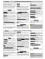
SCHEDA BASE ZBXE -
ZBXE MOTHERBOARD
- CARTE BASE ZBXE -
GRUNDPLATINE ZBXE
- TARJETA BASE ZBXE
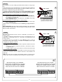
MAIN COMPONENTS
1 Terminal block for external connections
2 5A line fuses
3 1A accessories fuse
4 Socket radiofrequency board
5 Radio code and program encoder signal LED
6 Buttons for storing radio code and limit switch
programming
7 "Function selection" dip-switch
8 Trimmer AP.PARZ.: Partial opening adjustment
9 Trimmer TCA: automatic closing time adjustment
10 24V voltage signal LED
11 Fixed Encoder mother board
COMPOSANTS PRINCIPAUX
1 Plaque à bornes pour les branchements
2 Fusibles de ligne 5A
3 Fusible accessoires 1A
4 Branchement carte radiofréquence
5 LED de signalisation code radio et prog. encoder
6 Boutons-poussoirs mémorisation codes code radio et
programmation fin de course
7 Dip-switch "sélection fonction"
8 Trimmer AP.PARZ.: Réglage Ouverture partielle
9 Trimmer TCA: Réglage Temps de fermeture automatique
10 LED de signalisation tension 24V
11 Carte fixe Encodeur
COMPONENTES PRINCIPALES
1 Caja de bornes para las conexiónes
2 Fusibles de linea 5A
3 Fusible accesorios 1A
4 Conexión tarjeta radiofrecuencia
5 LED de señal código radio y programación encoder
6 Teclas memorización código radio y programación final
de carrera
7 Dip-switch "seleción función"
8 Trimmer AP.PARZ.: Regulación Apertura parcial
9 Trimmer TCA: Regulación cierre automático
10 LED de señal de tensión 24V
11 Tarjeta fija Encoder
HAUPTKOMPONENTEN
1 Anschluss-Klemmenleiste
2 5A-Sicherung Leitungs
3 1A-Sicherung Zubehörs
4 Steckanschluß Funkfrequenze-Platine
5 Anzeige-LED Funkcode und Programmier encoder
6 Funkcode-Speichertasten und Endausschalter-
Programmiertaste
7 "Funktionswahl" dip-switch
8 Trimmer AP.PARZ.: Einstellung Teilöffnung
9 Trimmer TCA: Einstellung Zeiteinstellung
Schließautomatik
10 Anzeige-LED der 24V-Spannung
11 feste Encoder-Platine
D
GB
COMPONENTI PRINCIPALI
1 Morsettiere di collegamento
2 Fusibili di linea 5A
3 Fusibile accessori 1A
4 Innesto scheda radiofrequenza
5 LED di segnalazione codice radio e prog. encoder
6 Pulsanti memorizzazione codice radio e prog. finecorsa
F
E
I
7 Dip-switch "selezione funzioni"
8 Trimmer AP.PARZ.: regolazione apertura parziale
9 Trimmer TCA: regolazione tempo di chiusura automatica
10 LED di segnalazione di tensione 24V
11 Scheda fissa Encoder
CHIUDE / CH1
APRE / CH2
AF
ENCODER
AP.PARZ.
T.C.A.
21 345678910O
N
1
2
3
4
10
6
7
8 9 5
11
Dis. 26221
La pagina sta caricando ...

12
Pulsante chiude (N.O.)
Close button (N.O.)
Poussoir de fermeture (N.O.)
Taste Schließen (Arbeitskontakt)
Pulsador de cierre (N.O.)
Contatto radio e/o pulsante per comando (vedi dip-switch 2-3-4 sel.funzioni)
Contact radio and/or button for control (see dip-switch 2-3-4function selection)
Contact radio et/ou poussoir pour commande (dip-switch 2-3-4 sel.fonction)
Funkkontakt und/oder Taste Steuerart (dip-switch 2-3-4
Funktionswahl)
Contacto radio y/o pulsador para mando (dip-switch 2-3-4 sel.fonción)
Contatto (N.C.) di «riapertura durante la chiusura»
Contact (N.C.) for «re-aperture during closure»
Contact (N.F.) de «réouverture pendant la fermeture»
Kontakt (Ruhekontakt) Wiederöffnen beim Schliessen
Contacto (N.C.) para la apertura en la fase de cierre
Contatto (N.C.) stop parziale
Partial stop contact (N.C.)
Contact (N.F.) d'arrêt partial
Teil-Stop (Ruhekontakt) Kontakt
Contacto (N.C.) de stop parcial
Lampada spia (24V-3W) cancello aperto
24V-3W gate-opened signal lamp
Lampe-témoin (24V-3W) portail ouverture
Signallampe (24V-3W), Öffnen
Lampara indicadora (24V-3W) puerta abierta
Collegamento antenna
Antenna connection
Connexion antenne
Antennenanschluß
Conexión antena
Uscita contatto (N.O.) Portata contatto: 5A a 24V(d.c.)
Contact output (N.O.) Resistive load: 5A 24V (d.c.)
Sortie contact (N.O.) Portée contact: 5A a 24V(c.c.)
Ausgang Arbeitskontakt Stromfestigkeit: 5A bei 24V (Gleichstrom)
Salida contacto (N.O.) Carga resistiva: 5A a 24V (d.c.)
Uscita per comando simultaneo di n.2 motori abbinati
Connection for simultaneous control of 2 combined motors
Sortie pour commande simultanée de 2 moteurs accouples
Ausgang zur gleichzeitigen Steuerung von 2 parallelgeschalteten Motoren
Salida para el mando simultáneo de n.2 motores acoplados
2 2
2 2
2
7 7
7 7
7
2 2
2 2
2
C1C1
C1C1
C1
2 2
2 2
2
C3C3
C3C3
C3
1010
1010
10
5 5
5 5
5
B1B1
B1B1
B1
B2B2
B2B2
B2
2MOT 2MOT
2MOT 2MOT
2MOT
2 2
2 2
2
4 4
4 4
4
L1
L2
UVWE
10 11 1 2 3 3P 4 5 7
2MOT
E
_
_
_
2C1C3B1B2

13
1
234
L2T
L1T
0
24
12
LIMITATORE DI COPPIA MOTORE /
MOTOR TORQUE LIMITER
/ LIMITEUR DE COUPLE MOTEUR
DREHMOMENTBEGRENZER DES MOTORS
/ LIMITADOR DE PAR MOTOR
COLLEGAMENTO A TERRA /
EARTH CONNECTION
/ BRANCHEMENT Á LA TERRE
ERDUNG
/ CONEXIÓN A TIERRA
(A)
Conecte el hilo de
tierra usando el
tornillo
autoterrajante (A) de
serie.
Das Massekabel
anschließen und
dazu die
selbsteinschneidenden
Schrauben verwen-
den (A), die der
Packung beiliegen.
Para variar el par
motor, desplazar el
faston indicado
hasta una de las 4
posiciones; 1 mín. -
4 máx.
Zur Änderung des
Motor-Drehmoments
den angegebenen
Faston auf eine der 4
Stellungen
positionieren: 1 min. -
4 max.
Pour varier le couple
du moteur, déplacer
le connecteur
indiqué sur l'une des
4 positions; 1 min. -
4 max.
To vary the motor
torque, move the
indicated faston to
one of the four
positions: 1=min,
4=max.
Per variare la coppia
motore, spostare il
faston indicato su
una delle 4 posizio-
ni; 1 min - 4 max.
Collegare il filo di
terra usando la vite
automaschiante (A)
in dotazione.
Connect the earth wire
by using the provided
self-tapping screw (A).
Brancher le fil de
terre en utilisant la
vis autoforeuse (A)
fournie de série.

14
AF
ENCODER
21 345678910O
N
APRE / CH2
AF
ENCODER
21 345678910O
N
CHIUDE / CH1
APRE / C H2
AP.PARZ. T.C.A.
Chiudere lo sportello dello sblocco e inserire il dip-switch 8 in ON, il led di
segnalazione inizia a lampeggiare (1). Portare il cancello in finecorsa chiude,
premere il tasto "CHIUDE", il led rimane acceso finchè si mantiene premuto
il tasto (2).
Procedere portando il cancello a finecorsa apre e premere il tasto "APRE" (3).
Riposizionare il Dip-switch 8 in OFF (4), aprire lo sportello e inserire la
manopola di sblocco.
N.B. In fase di programmazione finecorsa apre, se premendo il tasto "APRE"
il led rimane spento, invertire le fasi del motore ed Encoder come illustrato (5).
Close the door panel of the outlet and set dip-switch 8 to ON. The LED will
begin flashing (1). Bring the gate to the close limit-switch, press button
“CHIUDE”; the LED will remain lit as long as the button is released (2).
Now, move the gate to the end-of-travel position when open, and press the
"APRE" key (3).
Move Dip-switch 8 to OFF (4), open the access door and turn the release
Knob.
N.B. If the LED does not light up when the "APRE" key is pressed to program
the end-of-travel position when opened, reverse the motor and encoder
connections as shown on the diagram (5).
Fermer le volet de déblocage et insérer le dip-switch 8 sur ON, le del de
signalisation commence à clignoter (1). Mettre le grille sur la butée de fin de
course ferme, appuyer sur la touche “CHIUDE“, le led reste allumé tant que
l’on appuie sur la touche (2).
Procéder en amenantle portail en position de fin de course ouverture puis
appuyer sur la touche "APRE" (3). Déconnecter le Dip-switch 8 sur OFF (4),
ouvrir la porte et insérer la poignée de déblocage.
N.B. Pendant la phase de programmation de la fin de course ouverture, si, en
appuyant sur la touche "APRE", le led reste éteint, inverser les phases du
moteur et de l'encodeur de la façon indiquée (5).
Schließen Sie das Freigabetürchen und schalten Sie den Dip-Switch 8 auf ON.
Jetzt beginnt die Kontrolleuchte zu blinken (1). Das Tor bis zum Endanschlag
Schließen bringen. Dazu die Taste "CHIUDE" drücken. Das LED bleibt so
lange an, wie die Taste gedrückt gehalten wird (2).
Das Tor ganz Öffnen (Öffnungsendstellung) und die Taste "APRE" drücken
(3).
Dip-Switch 8 ausschalten (4), Abdeckung öffnen und Entriegelungsgriff
einfügen.
HINWEIS: wenn die Anzeige-LED wõhrend des Drückens der Taste "APRE"
in der Öffnungsendschalter-Programmierphase erloschenbleibt, dann sind
die Anschlüsse der Motorphasendrõhte und des Encoders der Abbildung
entsprechend zu wechseln (5).
Cierre la tapa del dispositivo de desbloqueo y conecte el dip-switch 8 en ON;
el indicador luminoso inicia a parpadear (1). Lleve la verja hasta el final de
carrera de cierre, pulsar la tecla “CHIUDE”; el indicador luminoso permanece
encendido mientras se mantenga apretado la tecla (2).
Proceder llevando la puerta a la posición final de carrera abre, pulsar la tecla
"APRE" (3).
Desconetar el Dip-switch 8 en OFF (4), abrir la portezuela e introducir la
manópola de desbloqueo.
NOTA. En la fase de programación final de carrera abre, si pulsando la tecla
"APRE" el LED está apagado, invertir las fases del motor y Encoder como
indicado en la figura (5).
LED intermittente
Signal LED
LED de signalisation
Anzeige-LED
LED de señal
PROGRAMMAZIONE FINECORSA -
LIMIT SWITCH PROGRAMMING -
PROGRAMMATION FIN DE COURSE
ENDAUSSCHALTER-PROGRAMMIER -
PROGRAMMACION FINAL DE CARRERA
ITALIANO
ENGLISH
FRANÇAIS
ESPANOL
DEUTSCH
2
1 34567
8910
ON
CHIUDE / CH1
APRE / C H2
AP.PARZ. T.C.A.
CHIUDE
2
LED acceso
Signal LED
LED de
signalisation
Anzeige-LED
LED de señal
1
3
LED acceso
Signal LED
LED de signalisation
Anzeige-LED
LED de señal
4
APRE
montaggio a sinistra vista interna
mounting on the left-hand side
of the gate
montage à gauche vue de l'intérieur
die Montage auf der linken Seite
angeschlossen, interne Ansicht
montaje a la izquierda vista interior
E1
UVW
M
E
2
1
3
45
6
78910
ON
eventuale montaggio a destra
if right-hand installation is desired
éventuel montage à droite
eventuelle Montage auf der rechten
Seite
eventual montaje a la derecha
U
VWE1
M
E
5

15
COLLEGAMENTO PER 2 MOTORI ABBINATI -
CONNECTIONS FOR 2 COMBINED MOTORS
CONNEXIONS POUR 2 MOTEURS ACCOUPLÉS
ANSCHLUSSE FÜR 2 PARALLELGESCHALTETEN MOTOREN
- CONEXIÓN PARA 2 MOTORES ACOPLADOS
AB
1
AF
ENCODER
2
SCHEDA RADIOFREQUENZA "AF"
"AF" RADIO FREQUENCY BOARD
CARTE FREQUENCE RADIO "AF"
RADIOFREQUENZKARTE «AF»
TARJETA RADIOFRECUENCIA AF
E
/ CH1
/
CH2
AP.PARZ. T.C.A.
21 345678910O
N
FUNZIONI
FUNCTIONS
FONCTIONS
FUNKTIONEN
FUNCIONES
3
REGOLAZIONI
SETTING
RÉGLAGES
EINSTELLUNGEN
REGULACIONES
UVWE
10 11 1 2 3 3P 4 5 7
2M O T
2C1C3B1B2
COLLEGAMENTI ELETTRICI
ELECTRICAL CONNECTIONS
BRANCHEMENTS ÉLECTRIQUES
ELEKRISCHE ANSCHLÜSSE
CONEXIONES ELÉCTRICAS
ENGLISH
In case two combined motors are installed, proceed in the following man-
ner:
- Match the directions
(
1) in which gear motors A and B rotate by chang-
ing the direction in which motor B rotates, see page 14 “limit switch
programming” point 5;
- Decide between A and B which is to be the Master motor (or pilot, i.e. the
motor that controls both the gates) and which is to be the Slave (i.e. that
piloted by the Master), then
on the Master control board:
- check that the (AF) radio frequency board is fitted (2);
- make the normal electrical connections and select the functions
desired (3);
- set the dip-switch 7 to ON and dip-switch 9 to OFF on the func-
tion selector (4);
on the Slave control board:
- set the dip-switch 7 to OFF and dip-switch 9 to ON on the func-
tion selector (5);
- Wire the electrical connections between the terminal boards, as shown
(6)
NB: If the two coupled gates are of different sizes, the master function
must be fitted to the motor control board installed on the longer door.
FRANÇAIS
Procéder comme suit en cas d'installation de deux moteurs accouplés:
- Coordonner le sens de marche (1) des motoréducteurs "A" et "B" en modi-
fiant le sens de rotation du moteur "B", voir page 14 "programmation interrup-
teur de fin de course" point 5;
- Entre les deux moteurs A et B, choisir quel est celui qui doit être Master (ou
pilote, c'est-à-dire le moteur qui commande les deux grilles) et Slave (c'est-
à-dire celui piloté par le moteur master) et puis
sur la carte de commande du moteur Master:
- contrôler si carte AF de radiofréquence (2) a été insérée;
- effectuer les branchements électriques normaux et sélectionner les
fonctions voulues (3);
- mettre les microinterrupteurs 7 in ON et 9 in OFF sur le sélecteur
des fonctions (4);
sur la carte de commande du moteur Slave:
- mettre les microinterrupteurs 7 in OFF et 9 in ON sur le sélecteur
des fonctions (5);
- Effectuer les branchements comme indiqué sur la figure (6) entre les pla-
ques à bornes
NOTE: Si les deux grilles accouplées n'ont pas la même dimension, la fonc-
tion master doit être insérée dans le tableau du moteur installé sur la porte la
plus longue.
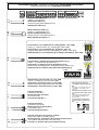
ITALIANO
Nel caso di installazione di due motori abbinati, procedere nel seguente modo:
- Coordinare il senso di marcia (1) dei motoriduttori "A" e "B", modificando la
rotazione del motore "B", vedi pag. 14 "programmazione finecorsa" punto 5;
- Stabilire tra A e B quale deve essere il motore Master (o pilota, cioè il motore
che comanda ambedue i cancelli) e quale Slave (e cioè quello pilotato dal
master); quindi
sulla scheda comando del Master:
- assicurarsi che sia inserita la scheda AF di radiofrequenza (2);
- eseguire i normali collegamenti elettrici e selezionare le funzioni
desiderate (3);
- posizionare il dip 7 in ON e il 9 in OFF sul selettore funzioni (4);
sulla scheda comando dello Slave:
- posizionare il dip 7 in OFF e il 9 in ON sul selettore funzioni (5);
- Eseguire tra le morsettiere i collegamenti come da figura (6)
NOTA: Se i due cancelli abbinati sono di dimensioni diverse, la funzione
master deve essere inserita nel quadro del motore installato sull'anta più
lunga.
La pagina sta caricando ...

17
CHIUDE / CH1
APRE / CH2
AF
ENCODER
AP.PARZ. T.C.A.
2
1 34567
8910
O
N
SELEZIONI FUNZIONI -
SELECTION OF FUNCTIONS
- SÉLECTION FONCTIONS
FUNKTIONSWAHL
- SELECCIÓN DE LAS FUNCIONES
ON
OFF
DIP-SWITCH 10 VIE
/ 10-WAY DIP-SWITCH
/ DIP-SWITCH 10 VOIES
ZEHNWEG-DIP-SWITCH /
DIP-SWITCH 10 VÍAS
FRANÇAIS
1 ON Fonction fermeture automatique sélectionnée;
2 ON Fonction "ouverture-stop-fermeture-stop" avec bouton
(2-7) et commande-radio sélectionnée;
2 OFF Fonction "ouverture-fermeture" avec bouton (2-7) et
commande-radio sélectionnée;
3 ON Fonction "seulement ouverture" avec commande-radio
sélectionnée;
4 ON Fonction "contact mantenu" sélectionnée (exclut la
fonction radiocommande)
5 ON Fonction preclignotement sélectionnée (Temps fix
5sec.);
6 ON Dispositif de détection de présence, à moteur arrête,
sélectionnée;
7 ON - 9 OFF Fonction "Master" sélectionnée (seulement
pour le branchement accouplé, voir p. 15);
8 ON Fonction "Spare" (programmation fin de course) sé-
lectionnée;
9 ON - 7 OFF Fonction "Slave" sélectionnée (seulement pour
le branchement accouplé, voir p. 15);
10 ON - 1 ON Fonction lampe cycle sélectionnée;
ESPANIOL
1 ON Función cierre automático activada;
2 ON Función "apertura-stop-cierre-stop" con botón (2-7) y
radiomando activada;
2 OFF Función "apertura-cierre" con botón (2-7) y radiomando
activada;
3 ON Función "sólo apertura" con radiomando activada;
4 ON Función "hombre presente" activada (escluye la fun-
ción del radiomando)
5 ON Función preintermitencia activada; (tiempo fijo 5 sec.)
6 ON Función detección del obstàculo, a motor parado, acti-
vada;
7 ON - 9 OFF Función "Master" activada (sólo para la co-
nexión combinada, véase p.15)
8 ON Función "Spare" (programación final de carrera) activa-
da;
9 ON - 7 OFF Función "Slave" activada (sólo para la co-
nexión combinada, véase p.15)
10 ON - 1 ON Función lámpara ciclo activada;
ITALIANO
1 ON Chiusura automatica attivata;
2 ON Funzione "apre-stop-chiude-stop" con pulsante (2-7) e
radiocomando attivata;
2 OFF Funzione "apre-chiude" con pulsante (2-7) e
radiocomando attivata;
3 ON Funzione "solo apertura" con radiocomando attivata;
4 ON "uomo presente" attivato (esclude la funzione del
radiocomando);
5 ON Prelampeggio attivato (tempo fisso 5 sec.);
6 ON Rilevazione ostacolo, a motore fermo, attivato;
7 ON - 9 OFF Funzione "Master" attivata; (solo per collega-
mento abbinato, pag. 15);
8 ON Funzione "Spare" attivata (programmazione
finecorsa);
9 ON - 7 OFF Funzione "Slave" attivata; (solo per collega-
mento abbinato, pag. 15);
10 ON - 1 ON Funzione lampada ciclo attivata;
ENGLISH
1 ON Automatic closure function enabled;
2 ON "Open-stop-close-stop" function with button (2-7) and
radio control enabled;
2 OFF "Open-close" function with button (2-7) and radio
control enabled,
3 ON "Only open" function with radio control enabled;
4 ON "Present man" operation enabled (and radio remote
control deactivated)
5 ON Pre-flashing function enabled (5 sec. fixed time);
6 ON Obstacle detection device, with motor stopped,
enabled;
7 ON - 9 OFF "Master" function enabled (only for coupled
connection, see pag. 15);
8 ON "Spare" function (limit switch programming) enabled;
9 ON - 7 OFF "Slave" function enabled (only for coupled
connection, see pag. 15);
10 ON - 1 ON Courtesy light function enabled;
2
1 34567
8910
O
N
DEUTSCH
1 ON Funktion Schließautomatik zugeschaltet;
2 ON Funktion "Öffnen-stop-Schließen-stop" mit Druckknopf
(2-7) und Fernsteuerung zugeschaltet;
2 OFF Funktion "Öffnen-Schließen" mit Druckknopf (2-7) und
Fernsteuerung zugeschaltet;
3 ON Funktion "nur Öffnen" mit Fernsteuerung zugeschaltet;
4 ON Bedienung vom "Steuerpult" zugeschaltet (bei Wahl
dieser Betriebsart wird die Funkfernsteuerung ausge-
schlossen)
5 ON Funktion Vorblinker zugeschaltet (Zeiteinstellung feste
5 sek.);
6 ON Funktion Hindernisaufnahme, bei stillstehendem Motor,
zugeschaltet;
7 ON - 9 OFF Master-Funktion zugeschaltet (nur für kombi-
nierte Anschlüsse, siehe S. 15);
8 ON Funktion "Spare" (Programmierendausschalter) zu-
geschaltet;
9 ON - 7 OFF Slave-Funktion zugeschaltet (nur für kombi-
nierte Anschlüsse, siehe S. 15);
10 ON - 1 ON Funktion Beleuchtung Zyklus zugeschaltet;

18
ENGLISH
PROCEDURE
A. insert an
AF card **.
B. encode
transmitter/s.
C. store code in the
motherboard.
FRANÇAIS
PROCEDURE
A. placer une carte
AF **.
B. codifier le/s
émetteur/s.
C. mémoriser la
codification sur
la carte base.
DEUTSCH
PROZEDUR
A. Stecken Sie eine
Karte AF **.
B. Codieren Sie den/
die Sender.
C. Speichern Sie die
Codierung auf der
Grundplatine.
ZBXE
INSTALLAZIONE DEL RADIOCOMANDO -
RADIO CONTROL INSTALLATION -
INSTALLATION DE LA RADIOCOMMANDE
INSTALLATION DER RADIOSTEUERUNG -
INSTALACIÓN DEL RADIOMANDO
ITALIANO
PROCEDURA
A. inserire una
scheda AF **.
B. codificare il/i
trasmettitore/i.
C. memorizzare la
codifica sulla
scheda base.
ESPANOL
PROCEDIMIENTO
A. introducir una
tarjeta AF **.
B. codificar el/los
transmisor/es.
C. memorizar la
codificación en
la tarjeta base.
La schedina AF deve essere inserita OBBLIGATORIAMENTE in assenza di tensione, perché la scheda madre la riconosce
solo quando viene alimentata
The AF board should ALWAYS be inserted when the power is off because the motherboard only recognises it when it is
powered.
La carte AF doit OBLIGATOIREMENT être branchée en l’absence de tension car la carte mère ne la reconnaît que quand
elle est alimentée.
Vor Einschieben der Karte die Stromzufuhr UNBEDINGT abschalten, da die Erkennung durch die Hauptkarte nur über eine
Neueinschaltung ( nur durch Versorgung) erfolgt.
La tarjeta AF se debe montar OBLIGATORIAMENTE en caso de falta de corriente, porque la tarjeta madre la reconoce sólo
cuando está alimentada
(**) Per trasmettitori con frequenza 433.92 AM (serie
TOP e serie TAM) bisogna, sulla relativa scheda AF43S,
posizionare il jumper come illustrato.
(**) On AM transmitters operating at 433.92 MHz
(TOP and TAM series), position the jumper
connection on circuit card AF43S as shown on the
sheet.
(**) Pour les émetteurs de fréquence 433.92 AM (série
TOP et série TAM) il faut positionner le pontet sur la
carte AF43S correspondante de la façon indiquée.
(**) Bei Sendern mit einer Frequenz von 433.92 AM
(Reihe TOP und Reihe TAM) ist der auf der
entsprechenden Platine AF43S befindliche Jumper
der Abbildung entsprechend zu positionieren.
(**) Para transmisores con frecuencia 433.92 AM (serie
TOP y serie TAM) es necesario, en la tarjeta
corespondiente AF43S, colocar el jumper como se
indica
TOP TAM
AF43S/SM
SCHEDA BASE
MOTHERBOARD
CARTE DE BASE
BASISKARTE
TARJETA BASE
SCHEDA "AF"
"AF" BOARD
CARTE "AF"
KARTE «AF»
TARJETA «AF»
zHM/azneuqerF
zHM/ycneuqerF
zHM/ecneuqerF
zHM/zneuqerF
zHM/aicneucerF
azneuqerfoidaradehcS
draobycneuqerfoidaR
ecneuqérfoidaretraC
enitalP-zneuqerfknuF
aicneucerfoidaratejraT
erotittemsarT
rettimsnarT
ruettemE
rednesknuF
rosimsnarT
599.62MF 031FA MFT
009.03MF 051FA MFT
599.62MA 62FA POT
009.03MA 03FA POT
29.334MA
MS34FA/S34FA POT/MAT
RS34FA OMOTA
INSERIMENTO SCHEDA AF -
AF BOARD INSERTION
- NSTALLATION DE LA CARTE AF
EINSTECKEN DER KARTE AF -
MONTAJE DE LA TARJETA AF
A

19
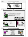
CODIFICA TRASMETTITORI -
TRANSMITTER ENCODING
- CODIFICATION DES EMETTEURS
CODIERUNG DER SENDER
- CODIFICACIÓN TRANSMISORES
B
TOP
QUARZATI
- QUARTZ
- AU QUARTZ
- QUARTZGENAUE
- CUARZO
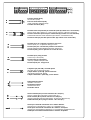
PROCEDURA COMUNE DI CODIFICA
T262M-T264M-T2622M
T302M-T304M-T3022M
1.segnare un codice (anche per archivio)
2.inserire jumper codifica J
3.memorizzarlo
4.disinserire jumper J
STANDARD ENCODING PROCEDURE
T262M-T264M-T2622M
T302M-T304M-T3022M
1.assign a code (also on file)
2.connect encoding jumper J
3.register code
4.disconnect jumper J
PROCEDURE COMMUNE DE CODIFICATION
T262M-T264M-T2622M
T302M-T304M-T3022M
1.taper un code (également pour les
archives)
2.placer un cavalier de codification J
3.mémoriser le code
4.enlever le cavalier J
ANLEITUNGEN ZUR CODIERUNG
T262M-T264M-T2622M
T302M-T304M-T3022M
1.Ordnen Sie einen Code zu (auch für das
Archiv).
2.Schalten Sie den Codierungs-Jumper J ein.
3.Speichern Sie den Code.
4.Schalten Sie den Jumper J wieder aus.
PROCEDIMIENTO COMÚN DE CODIFICACIÓN
T262M-T264M-T2622M
T302M-T304M-T3022M
1.marcar un código (también para el
archivo)
2.conectar un jumper codificación J
3.registrar el código
4.desconectar jumper J
2.
J
ON
OFF
P1
P2
codice/
codice
/codice/
codice
/codice
1.
4.
J
premere in sequenza P1 o P2 per registrare il
codice; al decimo impulso un doppio suono
confermerà l'avvenuta registrazione
Press P1 or P2 in sequence in order to register
the code; at the tenth pulse, a double beep will
confirm that registration has occurred
appuyer en séquence sur P1 ou P2 pour
mémoriser le code; à la dixième impulsion, une
double sonnerie confirme que le code a été
mémorisé
Drücken Sie nacheinander P1 oder P2, um den
Code zu speichern. Nach dem zehnten Impuls
signalisiert ein doppelter Piepton, daß der Code
gespeichert worden ist.
oprimir repetidamente P1 ó P2 para registrar el
código; con el décimo impulso un doble sonido
señalará que el registro se ha efectuado.
P1=OFF
P2=ON
3.
P1 P2
T2622M - T3022M
2° codice/
codice
/codice/
codice
/codice
ON
OFF
P1
P2
P3=CH1
P4=CH2
J
1° codice/
codice
codice/
codice
/codice
P1=CH1
P2=CH2
J
P1 P2
P3 P4
P1=CH1 - P2=CH2
P3=CH3 - P4=CH4
J
T264M - T304M
La prima codifica deve essere effettuata mantenendo i jumper
posizionati per i canali 1 e 2 come da fig. A; per eventuali e succes-
sive impostazioni su canali diversi vedi fig. B
The first encoding operation must be carried out whilst keeping the
jumpers positioned for channels 1 and 2 as per fig. A; see fig. B for
any subsequent settings on different channels.
La première codification doit être effectuée en maintenant les
cavaliers en position pour les canaux 1 et 2, comme d'après la fig.
A; pour des saisies successives éventuelles sur des canaux
différents, voir fig. B
Für die erste Codierung muß der Jumper auf den Kanälen 1 und 2
positioniert bleiben (siehe Abb. A). Für eventuelle weitere oder
spätere Einstellungen auf anderen Kanälen halten Sie sich bitte an
Abb. B.
La primera codificación tiene que efectuarse manteniendo los
jumper conectados para los canales 1 y 2 como se ilustra en la fig.
A; para planteamientos posteriores en canales distintos ver la fig. B
T262M - T302M
P1 P2
J
P1=CH1
P2=CH2
fig. A
fig. B
P1=CH1 - P2=CH4
P1=CH1 - P2=CH3
P1=CH3 - P2=CH2
P1=CH3 - P2=CH4
La pagina sta caricando ...

21
ITALIANO
-Assicurarsi che il dip 8 sia in
OFF (programmazione
finecorsa disattivata);
-Tenere premuto il tasto "CH1"
sulla scheda base (il led di
segnalazione lampeggia), con
un tasto del trasmettitore
s'invia il codice, il led rimarrà
acceso a segnalare l'avvenuta
memorizzazione (vedi fig.1).
Eseguire la stessa procedura
con il tasto "CH2" associandolo
con un altro tasto del trasmetti-
tore (fig.2).
CH1 = Canale per comandi
diretti ad una funzione della
centralina del motoriduttore
(comando "solo apre" / "apre-
chiude-inversione" oppure
"apre-stop-chiude-stop", a
seconda della selezione
effetuata sui dip-switch 2 e 3).
CH2 = Canale per comandi
diretti ad un dispositivo
accessorio collegato su B1-B2.
N.B.: Se in seguito si vuol
cambiare codice, basta
ripetere la sequenza descritta.
DEUTSCH
-Stellen Sie den Dip-Switch 8 auf
OFF (Programmierung
Endanschlag ausgeschlossen).
-Halten Sie die Taste CH1 an der
Basiskarte gedrückt (die
Kontrolleuchte blinkt). Senden
Sie den Code mit einer Taste
vom Sender. Der Kontrolleuchte
bleibt jetzt an und zeigt dadurch
das erfolgte Speichern an
(Abb.1).
Gehen Sie ebenso mit Taste CH2
vor und ordnen sie ihr eine an-
dere Taste des Senders zu
(Abb.2)
CH1 = Kanal für die Direkt-
steuerung einer Funktion des
Getriebemotor-Schaltkastens
(Steuerung "nur Öffnen" / "Öff-
nen-Schließen-Sicherheits-
rücklauf" bzw. "Öffnen-Stp-
Schließen-Stop", je nach über
Dip-Switch 2 und 3 ausgeführter
Wahl).
CH2 = Kanal für Direktsteuerung
eines über B1-B2 angeschlosse-
nen Zubehörs.
HINWEIS: bei eventuell er-
wünschter Sender
codeänderung ist der beschrie-
bene Vorgang zu wiederholen.
ESPANOL
-Coloque el dip 8 en OFF (programación final de carrera desactivada);
-Mantener oprimida la tecla "CH1" en la tarjeta base (el led de señalización parpadea), con una tecla del transmisor se envía el
código, el led permanece encendido para indicar que el almacenamendo se ha efectuado (fig.1).
Efectuar el mismo procedimiento con la tecla "CH2" asociándola a otra tecla del transmisor (fig.2).
CH1 = Canal para mando directo a una función de la central del motorreductor (mando "solo abre" / "abre-cierra-inversión" o "abre-
stop-cierra-stop", según la selección efectuada en los dip-switch 2 y 3).
CH2 = Canal para un mando directo a un dispositivo accesorio conectado en B1-B2.
NOTA: Si posteriormente se quisiera cambiar el código de los propios transmisores, sólo hay que repetir la secuencia descrita.
ENGLISH
-Position Dip 8 to OFF ( limit
switch programming deacti-
vated);
-Keep the CH1 key pressed on
the base card (the signal LED
will flash), and with a key on the
transmitter the code is sent, the
LED will remain lit to signal the
successful saving of the code
(figure 1).
Perform the same procedure
with the CH2 key, associating it
with another transmitter key
(figure 2).
CH1 = Channel for direct control
of one function performed by
the control unit on the gear
motor ("open only" / "open-
close-reverse" or "open-stop-
close-stop", depending on the
position of dip switches 2 and
3).
CH2 = Channel for direct control
of an accessory connected
across B1-B2.
N.B. If you wish to change the
code on your transmitters in the
future, simply repeat the proce-
dure described above.
FRANÇAIS
-Positionner le dip 8 sur OFF
(programmation des butées de
fin de course désenclenchée);
-Appuyer sur la touche "CH1"
sur la carte de base (le led de
signalisation clignote), avec
une touche du emetteur on en-
voie le code, le led restera al-
lumé pour signaler que la mé-
morisation s'est effectuèe
(fig.1).
Suivre la même procédure avec
la touche "CH2" en l'associant
avec une autre touche du
emetteur (fig.2).
CH1 = Canal pour obtenir la
commande directe d'une fonc-
tion du boîtier du
motoréducteur ( commande
"uniquement ouverture" /
"ouverture-fermeture-inversion"
ou "ouverte-stop-ferme-stop"
en fonction de la sélection ef-
fectuée sur les dip-switchs 2 et
3).
CH2 = Canal pour obtenir la
commande directe d'un dispo-
sitif accessoire branché sur B1-
B2.
N.B.: Si, successivement, on
veut changer le code des émet-
teur, il suffit de répéter la sé-
quence décrite ci-dessus.
MEMORIZZAZIONE CODICE -
CODE STORAGE
- MEMORISATION DU CODE
SPEICHERN VOM CODE
- MEMORIZACIÓN CÓDIGO
C
CHIUDE / CH1
APRE / CH2
AP.PARZ.
T.C.A.
Fig. 1 / Abb. 1
LED di segnalazione codice radio
Radio code signal LED
LED de signalisation code radio
Funkcode-Anzeigeleuchtdiode
LED de señal código radio
CHIUDE / CH1
APRE / CH2
AP.PARZ.
T.C.A.
Fig. 2 / Abb. 2
LED di segnalazione codice radio
Radio code signal LED
LED de signalisation code radio
Funkcode-Anzeigeleuchtdiode
LED de señal código radio
La pagina sta caricando ...
La pagina sta caricando ...
La pagina sta caricando ...
-
 1
1
-
 2
2
-
 3
3
-
 4
4
-
 5
5
-
 6
6
-
 7
7
-
 8
8
-
 9
9
-
 10
10
-
 11
11
-
 12
12
-
 13
13
-
 14
14
-
 15
15
-
 16
16
-
 17
17
-
 18
18
-
 19
19
-
 20
20
-
 21
21
-
 22
22
-
 23
23
-
 24
24


CAME BXE Manuale del proprietario
- Categoria
- Gate Opener
- Tipo
- Manuale del proprietario
in altre lingue
- English: CAME BXE Owner's manual
- français: CAME BXE Le manuel du propriétaire
- español: CAME BXE El manual del propietario
- Deutsch: CAME BXE Bedienungsanleitung

