
1
Documentazione
Tecnica
S20
rev. 1.1
01/2001
©
CAME
CANCELLI
AUTOMATICI
119BS20
SERIE BX |
BXSERIES
|
SÉRIE BX |
BAUREIHE BX
|
SERIE BX
BXE
CANCELLI AUTOMATICI
Automazioni per cancelli scorrevoli
Automation systems for sliding gates
Automatisations pour portails coulissant
Antriebe für den Schiebetore
Automatización para puertas correderas
3 x 1.5 / 230V
2 x 1 - TX
2 x 1
2 x 1.5
RG58
6
5
9
3
1
2
8
10
4 x 1 - RX
11
3 x 1.5 / 230V
2 x 1 - TX
3 x 1
2 x 1.5
RG58
6
5
4
8
3
1
2
9
9
2 x 1 - TX
4 x 1 - RX
10
4 x 1 - RX
7
1 - Gruppo BXE
2 - Quadro comando
incorporato
3 - Ricevitore radio
4 - Cremagliera
5 - Selettore a chiave
6 - Lampeggiatore di
movimento
7 - Antenna
8 - Fotocellule di
sicurezza
9 - Colonnina per
fotocellula
10 - Fermo anta
1 - BXE Antriebsmotor
2 - Schalttafel im Antrieb
3 - Funkempfänger
4 - Zahnstange
5 - Außenantenne
6 - Blinkleuchte “Tor in
Bewegung”
7 - Schlüsselschalter
8 - IR Lichtschranke
9 - Lichtschrankeensäule
10 -Toranschlag
1 - BXE unit
2 - Control panel
(incorporated)
3 - Radio receiver
4 - Rack
5 - Electric lock
6 - Flashing light indica-
ting door movement
7 - Antenna
8 - Safety photocells
9 - Photocell column
10 - Closure stop
Impianto tipo Installation type
Standard montage
Instalación tipo
1 - Conjunto BXE
2 - Cuadro de mando
incorporado
3 - Radiorreceptor
4 - Cremallera
5 - Selector mediante
llave
6 - Lámpara intermiten-
te de movimiento
7 - Antena receptora
8 - Fotocélulas de
seguridad
9 - Columna para
fotocélula
10 - Tope puerta
1 - Groupe BXE
2 - Armoire de
commande
incorporé
3 - Récepteur radio
4 - Crémaillère
5 - Sélecteur a clé
6 - Clignotant de
mouvement
7 - Antenne de
réception
8 - Photocellules de
sécurité
9 - Colonne pour
photocellule
10 - Butée d'arrêt
Standard installation

2
CARATTERISTICHE GENERALI -
GENERAL SPECIFICATIONS
- CARACTÉRISTIQUES GÉNÉRALES
ALLGEMEINES
- CARACTERÍSTICAS GENERALES
MISURE D'INGOMBRO -
OVERALL DIMENSIONS
- MESURES D'ENCOMBREMENT -
ABMESSUNGEN
- MEDIDAS
Progettato e costruito
interamente dalla CAME,
risponde alle vigenti
norme di sicurezza (UNI
8612), con grado di pro-
tezione IP54.
Garantito 12 mesi salvo
manomissioni.
Il a été entièrement
conçu et realisé par les
Ets CAME, conformé-
ment aux normes de
sécurité en vigueur
(NFP 25362) avec degré
de protection IP54.
Il est garanti 12 mois
sauf en cas d'endom-
magement.
Designed and construc-
ted entirely by CAME;
conforms to (UNI 8612)
safety standards with IP
54 protection rating.
12 mounth guarantee;
guarantee void if unit is
tampered with.
Vollständig von der CAME
geplant und hergestellt,
entsprechend den
geltenden Sicherheits-
bedigungen (UNI 8612)
mit Schutzgrad IP54.
12 Monate Garantie,
Bedienungs - und Monta-
gefehler ausgeschlossen.
Diseñado y construido
totalmente por CAME,
con arreglo a las vigen-
tes normas de seguridad
(UNI 8612) con grado de
protección IP54.
Garantia de 12 meses
salvo manipulaciones.
CARATTERISTICHE TECNICHE -
TECHNICAL CHARACTERISTICS -
CARACTERISTIQUES TECHNIQUES
TECNISCHE DATEN -
CARACTERISTICAS TECNICAS
240
105
150
290
125165
105
310
22 max.
-amissamatatroP
-stimilesU
xameétroP
-thciwegroT
atreuposeP
elaiznediserosu
laitnediseR
leitnediseregasu
ztasnienetavirp
laicnediserosu
008gK
MOTORIDUTTORE
GRADO DI
PROTEZIONE
PESO ALIMENTAZIONE ASSORBIMENTO POTENZA
INTERMITTENZA
LAVORO
COPPIA RAPPORTO DI RIDUZIONE SPI NTA VELOCITA' MAX. COND ENSATORE
GEARMOTOR
PROTECTION
RATING
WEIGHT POWER SU PPLY CUR REN T POWER DUTY CICLE MAX TORQUE
REDUC TION
RATIO
PUSH MAX. SPEED CAPACITOR
MOTORÉDUCTEUR
DEGRÉ DE
PROTECTION
POI DS ALI MENTATION ABSOR PTION PUISSAN CE
INTERMITTENCE
DE TRAVAIL
COU PLE RAPPORT DE RED UCTION POUSSÉE VI TESSE MAX. CONDENSATEU R
GETRIEBEMOTOR SCHUTZGRAD GEWICHT
STROM_
VERSORGUNG
STROMAUF NAH ME LEISTUNG EINSC HALTDAUER DREHMOMENT
UNTERSETZUNGS_
VERHÄLTN IS
REGELBARER
MAX.
ÜBERTRAGUNGS
KONDENSATOR
MOTORREDUCTOR
GRADO DE
PROTECCION
PESO ALIMENTACION ABSORBENCIA POTENCIA
INTERMITENCIA
TRABAJO
PAR E JA
(MOTOR)
RELACI ON DE
REDUC CION
EMPUJE
VELOCIDAD
MAX.
CONDENSADOR
BXE IP 54 15 Kg 230V a.c. 2,4A 300W 30 % * 32 Nm 1/33 800 N 10 m/min. 20 µF
* Ottenuta mediante quadro comando CAME
* Obtained with CAME control panel
* Obtenue au moyen armoire de commande CAME
* Erreicht mit Hilte der "CAME" Schalttafel
* Se obtiene mediante el cuadro de mando CAME

3
PRIMA DELL'INSTALLAZIONE ... -
BEFORE INSTALLING .....
- AVANT D'INSTALLER L'AUTOMATISME .....
VOR DEN INSTALLATION ÜBERPRÜFEN
... - ANTES DE INSTALAR EL AUTOMATISMO...
FISSAGGIO BASE MOTORE -
MOTOR TO BASE ANCHORAGE
- FIXATION DE LA PLAQUE DU MOTEUR
BEFESTIGUNGS DER MOTORBASIS
- FIJACIÓN BASE MOTOR
- La hoja de la puerta debe
estar suficientemente ri-
gida y compacta
- Las ruedas de desliza-
miento deben estar
perfecta y engrasadas
adecuadamente.
- La guia de deslizamiento
debe estar bien fijada en
el suelo, sobresaliendo a
lo largo de su entera
longitud, sin huecos ni
irregularidades (que
podrian obstaculizar el
movimiento de la puerta).
- La guia superior debe te-
ner el justo juego con la
puerta metálica (para
garantizar un movimiento
regular y silencioso).
- Disponer un tope para
apertura y el cierre.
- Disponer un conducto
para los cables eléctricos
que cumpla con las
disposiciones de mando
y seguridad.
- Die Leistungfähigkeit der
feststehenden und
beweglichen Teile des Tores
überprüfen.
- Das Tor sollte ausreichend
stabil sein. Die Gleitrollen
sollten in guten Zustand
und angemessen gesch-
miert sein.
- Die Gleitführung auf dem
Boden sollte sich in
optimaler Position befinden:
gut auf dem Boden
befestigt, in seiner
Gesamtlänge vollständig
über dem Boden, ohne
Vertiefungen und/oder
Unebenheiten, die die
Torbewegung behindern
können.
- Die oberen Führungs-
schienen sollten das
richtige Spiel zum Tor
haben, um ein präzises und
regelmäßiges Gleiten zu
garantieren.
- Einen Anschlag für Tor Auf
und Tor Tu sollte vorhanden
sein.
- Den Lauf der elektrischen
Kabel nach den Steuerungs
und Sicherheitsbestim-
mungen vorsehen.
- Le panneau mobile du
portail devra être suf-
fisamment rigide et soli-
de.
- Les roues de coulis-
sement devront être en
très bon état. En outre,
elles devront être conve-
nablement graissées.
- Le rail de guidage devra
être bien fixé au sol. De
plus, il devra se présenter
entièrement en surface
sans affaissement ou
irrégularité (qui pour-
raient empêcher le
mouvement du portail).
- Le guide supérieur devra
avoir un jeu convenable
avec le portail (pour
permettre un mouvement
régulier et silencieux).
- Prévoir une butée d’arrêt
à l’ouverture et à la
fermeture.
- Prévoir le passage des
câbles électriques selon
les dispositifs de com-
mande et de sécurité.
- The gate must be sufficiently
rigid and solid.
- The wheels on which the
gate slide must be in perfect
condition and adequately
lubricated.
- The wheel guide must be
firmly attached to the
ground, completely expo-
sed, and without any dips
or irregular sections which
might hinder the movement
of the gate.
- The upper guide must allow
for the correct amount of
play in order to guarantee
smooth and silent move-
ment of the gate.
- Opening and closure stops
must be installed.
- The wiring must be routed
as specified by the control
and safety requirements.
- Controllare che l'anta sia
rigida e compatta e che le
ruote di scorrimento
siano in buono stato e
adeguatamente ingras-
sate.
- La guida a terra dovrà
essere ben fissata al
suolo, completamente in
superficie in tutta la sua
lunghezza e priva di
irregolarità che possano
ostacolare il movimento
del cancello.
- I pattini-guida superiori
non devono creare attriti.
- Prevedere un fermo anta
in apertura e uno in
chiusura ed il percorso
dei cavi elettrici come da
impianto tipo.
- Inserire le viti nella piastra
di ancoraggio bloccan-
dole con i dadi in dota-
zione, ed estrarre le
zanche preformate verso
il basso.
- Predisporre, dimensio-
nandola in base alle
misure del motoriduttore,
una piazzola in cemento
(si consiglia di farla
sporgere dal terreno di
circa 50 mm.) con
annegata la piastra di
ancoraggio e relative
zanche sulla quale sara'
fissato il gruppo.
- La base di fissaggio
dovra' risultare perfet-
tamente in bolla, pulita in
tutte le sue estremita',
con il filetto delle viti
completamente in
superfice.
N.B.: Dalla stessa dovranno
emergere i tubi flessibili
per il passaggio dei cavi di
collegamento elettrico.
- Install the screws in the
anchor plate and fasten
them with a nut, then bend
the pre-formed clamps
downwards.
- Construct a cement
foundation that is large
enough to accomodate the
gear motor (it is a good idea
to protrude 50 mm. from the
ground). When pouring the
foundation, embed the gear
motor anchor plate and the
relative clamps in the
cement.
- The anchor bolts should be
embedded in the concrete
in the positions indicated;
the drive unit is then
attached to this bots. The
anchor plate must be
perfectly level and absolu-
tly clean; the bolts threads
must be completly
exposed.
N.B.: The flexible tubes for
the electrical wiring must be
embedded in the base and
protude in the correct
position.
- Introduire les vis dans la
plaque d'ancrage en les
bloquant avec un écrou,
et replier les agrafes
préformées ver le bas.
- Préparer une base en
ciment d'une dimension
adéquate aux mesures du
motoréducteur (il est con-
seillé de la faire dépasser
du terrain d'environ 50
mm.), et noyer dedans la
plaque d'ancrage et les
agrafes correspondantes
afin de permettre le
fixage du groupe.
- La base de fixation devrà
être parfaitement de
niveau et propre sur toute
sa surface et le filet des
vis devra être complè-
tement en surface.
N.B. Les câbles pour le
branchement électrique
devront sortir de cette
base.
- Die Schrauben in die
Ankerplatte einfügen und
mit einer Schraubenmutter
blockieren, die vorgefor-
mten Fundamentanker
nach unten umbiegen.
- Eine den Abmessungen
des Getriebemotors ents-
prechende Betonfunda-
mentplatte (Es empfiehlt
sich, diese ca. 50 mm. vom
Boden herausragen zu las-
sen) zum Einbetten der
Ankerplatte und der ents-
prechenden Fundamen-
tanker, die zur Befestigung
des Antriebsaggregats
dienen, vorbereiten.
- Die Befestigungs-unterlage
muß in seiner gesamten
Länge vollkommen eben
und sauber sein.
Das Gewinde der Schrau-
ben müssen gänzlich.
hervorstehen.
Wichtig: die Kabel für den
Elektroanschluß müssen
herausrgen.
- Introducir los tornillos en
la placa de anclaje,
bloqueándolos con una
tuerca, y doblar las
palancas preformadas
hacia abajo.
- Preparar, dándole las
dimensiones adecuadas
en función de las medi-
das del motorreductor,
una plataforma de ce-
mento (se aconseja
dejarla sobresalir del
suelo aprox. 50 mm.) con
la placa de enclaje
embedida y con las
correspondientes varil-
las, que permitrá la
fijación del grupo.
- La base de fijación debe
estar perfectamente
nivelada, limpia en todos
sus extremos, con la ro-
sca de los tornillos total-
mente in superficie.
N.B.: De ésta deben
sobresilar los tubos
flexibles para el paso de
los cables para las
conexiones eléctricas.
50 mm.
75 mm.
105 mm.
Struttura fissa
Wall
Structrure fixe
Feste Struktur
Estructura fija
Anta cancello
Gate wing
Panneau mobile du portail
Gleitachse
Puerta
Piazzola in cemento
Concrete base
Plate-forme en ciment
Plattenachse
Plataforma de cemento
Cavi
Cable
Câbles
Kabel
Cables
Cremagliera
Rack-limit
Cremaillére
Zahnstange
Cremallera
Piastra di ancoraggio / Zanche
Fixing plate / Anchor stays
Plaque de fixation / Agrafes
Gleitachse / Verankerung
Placa de fijación / Barras de fijción

4
INSTALLAZIONE DEL GRUPPO -
UNIT INSTALLATION -
INSTALATION DU GROUPE
AUFSTELLUNG DES AGGREGATS
- COLOCACIÓN DEL GRUPO
Nella fase preliminare di
installazione, i piedini
dovranno sporgere di 5-
10 mm. per permettere
allineamenti, fissaggio
della crema-gliera e
regolazioni successive.
L'accoppiamento esat-
to con la linea di scor-
rimento del cancello è
ottenibile dal sistema di
regolazione integrale
(brevettato) composto
da:
- le asole che permet-
tono la regolazione
orizzontale;
- i piedini filettati in
acciaio che permet-
tono la regolazione
verticale e la messa in
bolla;
- le piastrine e i dadi di
fissaggio che rendono
solidale l'aggancio del
gruppo alla base.
During the initial phase of
installation, the feet should
protrude by 5-10 mm. in
order to allow for
alignment, anchorage of
the rack and further
adjustments.
Perfect alignment with the
guide rail is made possible
by the (patented) built-in
regulation system, which
consists of:
- slots for horizontal
adjustment;
- threaded steel feet for
vertical adjustment and
levelling;
- plates and bolts for
anchorage to the base.
Dans la phase de
instalation préliminaire,
les broches devront
dépasser de 5 à 10 mm
afin de permettre les
alignements et les
réglages nécessaires
après la pose.
L’accouplement exact
avec la ligne de
coulissement du portail
s’effectue par le
système de réglage
hauteur (breveté) dont
le groupe est pourvu, et
qui comprend plus
précisément:
- les trous oblong
permettant le réglage
horizontal;
- les broches filetées en
acier qui donnent le
réglage vertical et la
mise à niveau;
- les plaques et les
écrous de fixation qui
assemblent solide-
ment le groupe à la
plaque de fixation
scellée.
Nun die Montage des
Antriebsmotors vorneh-
men. Die genaue Kop-
plung mit der Gleitlinie des
Tors wird von dem
integrierten Einstel-
lungssystem (patentiert)
garantiert, mit dem das
Aggregat ausgestattet ist
und zwar:
- die Osen für die
horizontale Einstellung,
- die Gewindefüße aus
Stahl für die vertikale
Einstellung und die
Nivellierung,
- die Befestigungsplät-
tchen und muttern zur
soliden Befestigung des
Aggregats an die
Bodenplatte.
Während der Vorberei-
tungsarbeiten der
Montage sollten die
Füße 5-10 mm herau-
sragen, um Ausfluch-
tungen und Einstellung
auch nach der Fertig-
stellung zu ermöglich.
En la fase previa de la
colocación, los pies
deben sobresalir 5-10
mm para consentir la
alineación, la fijación de
la cremallera y las regu-
laciones sucesivas.
El acoplamiento exacto
con la linea de desli-
zamiento de la puerta
metálica se obtiene me-
diante el sistema de
regulación integral
(patentado) que consta
de:
- los agujeros ovalados
que consienten la
regulación horizontal;
- las tuercas de acero
que permiten la
regulación vertical y la
nivelación;
- las placas y las tuercas
de fijación que hacen
solidario el enganche
del conjunto con la
base.
5÷10 mm.
Ingresso cavi
Cable entrances
Passage des câbles
Kabeleinführungen
Accoppiamento pignone-cremagliera
con gioco 1÷2 mm.
Rack-to-pinion coupling with 1÷2 mm. clearance
Assemblage pignon-crémailère avec jeu
de 1 à 2 mm.
Zwischen Zahnstange und dem Antriebsritzel
1÷2 mm. Spiel einstellen
Acoplamiento piñon-cremaliera
1÷2 mm. de juego
Regolazione orizzontale e fissaggio
Horizontal adjustment unit and achorage
Réglage horizontal et fixation
Horizontale Einstellung
Regulación horizontal y fijación
Regolazione verticale - messa in bolla
Vertical adjustment and unit leveling
Réglage vertical - mise à niveau
Vertikale Einstellung
Regulación vertical y nivelación
Entrada cables
1÷2 mm.

5
FISSAGGIO CREMAGLIERA-
ATTACHING THE RACK/LIMIT
- FIXATION CREMAILLÉRE
MONTAGE DE ZAHNSTANGE -
FIJACIÓN DE LA CREMALLERA
Con el fin de permitir al
ENCODER medir la
carrera de la puerta, fijar
la cremallera con el
mismo a mitad de
carrera:
- coloque la hoja en la
mitad de la carrera,
apoye la cremallera
sobre el piñon del
motorreductor y
deslice manualmente
la puerta, fijando la
cremallera a todo lo
largo;
- La carrera máxima de
la puerta es de 14 m;
- Finalizadas las ope-
raciones para la
fijacion de la cremal-
lera, regular los pies
(por medio de un
destornillador) de
modo que se obtenga
el justo juego entre el
piñón y la cremallera
(1-2 mm).
N.B. Esto hace que el
peso de la puerta
metálica no cargue
sobre el conjunto.
- Si la cremallera ya ha
sido fijada, hay que
regular el acoplamien-
to piñón-cremallera.
- Una vez realizados los
ajuste, fijar el conjunto
cerrando las dos
tuercas de fijación.
Ist der ENCODER zur
Erfassung bzw. Überwa-
chung des Torlaufs auf
halber Laufhöhe auf der
Zahnstange zu befesti-
gen:
- den Torflügel halb öffnen
und die Zahnstange auf
dem Ritzel vom
Getriebe-motor aufle-
gen. Dann das Tor von
Hand verschieben und
dabei die Zahnstange
auf ganzer Länge
befestigen;
- Der maximale Lauf vom
Tor beträgt 14 m;
- Die verstellbaren Füße
des Antriebsmotors (mit
einem Schrauben-
zieher) so einstellen,
daß zwischen Ritzel und
Zahnstange ein Spiel (1-
2 mm) besteht.
Wichtig: Dadurch wird
vermieden, daß das
Gewicht des Tores auf
dem Aggregat lastet.
- Nach diesen Einstel-
lungsarbeiten das
Aggregat durch Anzie-
hen der beiden Muttem
befestigen.
Afin de permettre à
l'ENCODEUR de rele-
ver la course du portail,
fixer la crémaillère avec
le portail à mi-course:
- mettre la porte à la
moitié de sa course,
poser la crémaillère
sur le pignon du
motoréducteur et faire
coulisser manuel-
lement le portail en
fixant la crémaillère sur
toute sa longueur;
- La course maximum du
portail est de 14 m;
- Lorsque la fixation de
la crémaillère est
terminée régler les
broches (en utilisant
un tournevis) de façon
à obtenir un jeu
convenable (1-2 mm)
dans l’assemblage du
pignon et de la
crémaillère.
N.B. Ceci pour éviter
que le poids du portail
ne repose sur le groupe.
- Si la crémaillère est
déjà fixée, utiliser le
système de réglage
hauteur pour assem-
bler correctement de
facon exacte le pignon
et la crémaillère.
- Exécuter tous les
réglages, fixer le
groupe en serrant les
deux écrous de
fixation.
Install the rack with the
gate at the half-way point.
This will enable the
ENCODER to detect
gate travel properly:
- allow the door to reach
mid-run, set the rack on
the rationmotor's pinion
and slide the gate
manually, fixing the
rack's entire lenght;
- The gate's maximum run
is 14 m;
- when the rack is attached
to the gate, adjust the
feet using a screwdriver
until the play between
the pinion and the rack is
correct (1-2 mm.).
N.B.: This position
ensures that the weight of
the gate does not rest on
the gearmotor.
- If the rack is already
attached, proceed
directly to the adjustment
of the rack/pinion
coupling.
- When the necessary
adjustment have been
completed, fasten the
unit in position by
tightening the two anchor
bolts.
Al fine di permettere
all'ENCODER di rileva-
re la corsa del cancello,
fissare la cremagliera
con il cancello a meta'
corsa:
- portare l'anta a meta'
corsa, appoggiare la
cremagliera sul
pignone del moto-
riduttore e far scorrere
manualmente il can-
cello fissando la
cremagliera in tutta la
sua lunghezza;
- La corsa massima del
cancello é di 14 m;
- ultimata l'operazione
di fissaggio della
cremagliera, regolare i
piedini (servendosi di
un cacciavite) in modo
da ottenere il giusto
giuoco tra pignone e
cremagliera (1-2 mm).
N.B. : Questo evitera'
che il peso del cancello
vada a gravare sul
gruppo.
- Se la cremagliera é gia'
fissata, procedere
direttamente alla re-
golazione dell'ac-
coppiamento pignone-
cremagliera.
- Eseguite tutte le
regolazioni, fissare il
gruppo stringendo i
dadi di fissaggio.

6
SBLOCCO MOTORIDUTTORE -
GEAR RELEASE
- OPÉRATION DE DÉBLOCAGE
- ANTRIEBSENTRIEGELUNG
DESBLOQUEO MOTORREDUCTOR
Per aprire lo sportellino
inserire la chiave,
spingerla e ruotala in
senso orario; sbloccare
quindi il motoriduttore
ruotando la manopola
nella direzione indicata.
Pour ouvrir la trappe,
introduire la clé, la
pousser et la tourner
dans le sens des
aiguilles d'une montre.
Débloquer ensuite le
motoréducteur en
tournant la poignée
dans la direction
indiquée.
Para abrir la portezuela
introducir la llave,
empujarla y girarla en
sentido horario;
desbloqear el motorre-
ductor girando la
manilla en la dirección
indicada.
To open the access door,
insert the key, push down
and rotate clockwise.
Now, release the gear
motor by rotating the knob
in the direction shown.
Zum Öffnen der klappe
den Schlüssel einfügen,
hineindrücken und im
Uhrzeigersinn drehen.
Dann den Getriebemotor
durch Drehen des Knopfs
in die angegebene
Richtung entsperren.
Release
Sblocco
Blocco
Engage
Blockierend
Entriegelt
Blocage
Déblocage
Desbloqueo
Bloqueo
CAME
ATTENZIONE:
l'apertura dello sportel-
lino di sblocco impedi-
sce il funzionamento del
motore.
ATTENTION:
the opening of the unblock
panel arrests the motor.
ATTENTION:
l’ouverture de la porte
de déblocage empêche
le fonctionnement du
moteur.
ACHTUNG:
Wenn das Freigabetür-
chen geöffnet wird,
funktioniert der Motor
nicht.
ATENCIÓN:
la apertura de la tapa de
desbloqueo, impide el
funcionamiento del
motor.

7
La scheda comando va alimentata a (230V
a.c.) sui morsetti L1 e L2 ed è protetto in
ingresso con fusibili da 5A e varistore V1.
I dispositivi di comandi sono a bassa tensio-
ne (24V), e sono protetti con fusibile da 1A
e varistori V2. La potenza complessiva de-
gli accessori a 24V, non deve superare i
20W.
Il tempo lavoro è fisso a 90 secondi.
SICUREZZA
Le fotocellule possono essere collegate e
predisposte per:
-
Riapertura
in fase di chiusura (2-C1);
-
Stop parziale,
arresto del cancello se in
movimento con conseguente pre-
disposizione alla chiusura automatica
(2-C3);
-
Stop totale,
(1-2) arresta il cancello esclu-
dendo l'eventuale ciclo di chiusura
automatica; per riprendere il movimento bi-
sogna agire sulla pulsantiera o sul
radiocomando;
Nota: Se un contatto di sicurezza normal-
mente chiuso (2-C1, 2-C3, 1-2) si apre,
viene segnalato dal lampeggio del LED di
segnalazione (n°11)
-
Rilevazione di presenza ostacolo.
A moto-
re fermo (cancello chiuso, aperto o dopo un
comando di stop totale), impedisce qualsia-
si movimento se i dispositivi di sicurezza
(es.fotocellule) rilevano un ostacolo.
- La scheda, inoltre, integra e gestisce auto-
maticamente una funzione di sicurezza che,
in caso di rilevazione di ostacoli, funziona
nel seguente modo:
This control board is powered by 230V AC
across terminals L1 and L2, and is protected
by a 5A fuse on the main power line with
varistor V1. Control systems are powered
by low voltage and protected with by a 1A
fuse with varistor V2.
The total power consumption of 24 V
accessories must not exceed 20 W.
Fixed operating time of 90 seconds.
SAFETY
Photocells can be connected to obtain:
-
Re-opening
during the closing cycle (2-
C1);
-
Partial stop,
shutdown of moving gate, with
activation of an automatic closing cycle (2-
C3);
-
Total stop,
(1-2) shutdown of gate
movement without automatic closing; a
pushbutton or radio remote control must be
actuated to resume movement;
Note: If a safety contact which is normally
closed (2-C1, 2-C3, 1-2) is opened, the LED
(n°11) will flash to indicate this fact;
-
Obstacle presence detection.
When the
motor is stopped (gate is closed, open or
half-open after an emercency stop
command), the transmitter and the control
pushbutton will be deactivated if an obstacle
is detected by one of the safety devices (for
example, the photocells).
- In addition, the board automatically
integrates and runs a safety function that
works in the following manner in case
obstacles are detected;
in apertura
il cancello inverte il senso di marcia fino alla
completa apertura;
in chiusura
il cancello inverte il senso di marcia fino alla
completa apertura con conseguente inter-
vento della chiusura automatica.
Attenzione! dopo tre inversioni consecuti-
ve, il cancello resta aperto escludendo la
chiusura automatica: per chiudere, usare il
radiocomando o il pulsante di chiusura.
ACCESSORI COLLEGABILI
-
Lampada ciclo.
Lampada che illumina la
zona di manovra, rimane accesa dal mo-
mento in cui l'anta inizia l'apertura fino alla
completa chiusura (compreso il tempo di
chiusura automatica). La funzione della lam-
pada ciclo si ottiene in uscita W-E1 solo se
i dip n°9 «chiusura automatica» e n°8
«rilevazione di presenza ostacolo» sono
posizionati in ON, vedi pagina 12;
-
Lampada spia cancello aperto.
Lampada
che segnala la posizione di apertura del
cancello e che si spegne quando il cancello
attiva il finecorsa chiude; collegarla ai
morsetti 10-5.
Nota: gli accessori a 24V non necessitano
di collegamento a terra.
ALTRE FUNZIONI
-
Chiusura automatica.
Il temporizzatore di
chiusura automatica si autoalimenta a
finecorsa in apertura. Il tempo prefissato
regolabile, é comunque subordinato dall'in-
tervento di eventuali accessori di sicurezza
e si esclude dopo un intervento di «stop»
totale o in mancanza di energia elettrica;
during opening
the gate inverts the movement direction until
it is completely close;
during closure
the gate inverts its direction until it is
completely open, after which it closes
automatically.
Warning! after three consecutive inversions,
the gate will remain open and automatic
closure will be discontinued. Toclose the
gate, use the radio remote control or the
push-button.
ACCESSORIES WHICH CAN BE
CONNECTED
-
Cycle lamp.
The lamp which lights the
manoeuvring zone: it remains lit from the
moment the gate begin to open until it is
completely closed (including the time
required for the automatic closure). The
function of the cycle lamp is obtained in
output W-E1 only if dip switch numbers: No.9
«automatic closing» and No.8 «detect
obstacle presence» are set to ON (see
page 12).
-
Open gate pilot lamp.
It is a light that indi-
cates the sliding gate's open position and
turns off when the gate activates the closing
end-stop, connect it to terminal blocks 10-5.
N.B.: the 24V accessories do not need a
earth connection.
OTHER FUNCTIONS
-
Automatic closing
. The automatic closing
timer is automatically activated at the end
of the opening cycle. The preset, adjustable
automatic closing time is automatically
interrupted by the activation of any safety
system, and is deactivated after a STOP
command or in case of power failure;
-
Partial opening.
Gate opening for passage
on foot is activated by connecting to the 2-
3P terminal blocks and it can be adjusted
by the AP.PARZ. trimmer;
-
"Operator present"
function: Gate operates
only when the pushbutton is held down (ra-
dio remote control is deactivated when
function is selected);
-
Programming
the calibration of the
electronic opening and closing limit
switches;
-
Master function;
the panel assumes all the
command functions when two paired
motors are used (see pag. 15);
-
Flashing light
activated before opening and
closing cycle begins;
-
Selection of command sequence:
-open-close-reverse;
-open-stop-close-stop;
-open only
ADJUSTMENTS
-Trimmer AP.PARZ. = Partial opening: 4" to
15";
-Trimmer TCA = Automatic closing time: 1"
to 160";
-
Apertura parziale.
Apertura del cancello
per passaggio pedonale, viene attivata col-
legandosi ai morsetti 2-3P ed è regolabile
mediante trimmer AP.PARZ.;
-
Funzionamento a uomo presente.
Funzio-
namento del cancello mantenendo premuto
il pulsante (selezionandolo si esclude la
funzione del radiocomando);
-
Programmazione
taratura dei finecorsa
elettronici di apertura e di chiusura;
-
Funzione master,
il quadro assume tutte le
funzioni di comando nel caso di due motori
abbinati (vedi pagina 15);
-
Prelampeggio
in apertura e chiusura;
-
Tipo di comando:
- apre-chiude-inversione;
- apre-stop-chiude-stop;
- solo apertura.
Regolazioni
- Trimmer AP.PARZ. = Apertura parziale:
da 4"a 15";
- Trimmer TCA = Tempo chiusura automa-
tica: da 1" a 160";
Attenzione:
- l'apertura dello sportellino di sblocco impe-
disce il funzionamento del motore.
- prima di intervenire all'interno dell'appa-
recchiatura, togliere la tensione di linea e
scollegare le batterie (se inserite).
Important:
- the opening of the unblock panel arrests
the motor.
- Shut off the mains power and disconnect
the batteries before servicing the inside of
the unit.
TECHNICAL DESCRIPTION ZBXE MOTHERBOARD
ENGLISH
DESCRIZIONE TECNICA SCHEDA BASE ZBXE
ITALIANO

8
La carte de commande doit être alimentée
avec une tension de 230V sur les bornes
L1 et L2 et elle est protégée en entrée par
un fusible de ligne de 5A avec varistor V1.
Les dispositifs de commande sont à basse
tension et protégés avec fusible de 1A avec
varistor V2. La puissance totale des
accessoires à 24V, ne doit pas dépasser
20W.
Temps de fonctionnement fixe de 90 sec.
SÉCURITÉ
Il est possible de brancher des
photocellules et de les programmer pour:
-
Réouverture
en phase de fermeture (2-
C1);
-
Stop partiel
, arrêt du portail, si en
mouvement, et conséquente programmation
pour la fermeture automatique (2-C3);
-
Stop total
, (1-2) arrêt du portail et
désactivation d’un éventuel cycle de
fermeture automatique; pour activer de
nouveau le mouvement, il faut agir sur les
boutons-poussoirs ou sur la radio-
commande;
Remarque: Le voyant (LED - n°11) de
signalisation qui clignote indique qu'un
contact de sécurité normalment fermé (2-
C1, 2-CX, 1-2) s'ouvre.
-
Détection de présence obstacle
.
Quand le moteur est arrête (portail fermé,
ouvert ou semi-ouvert, cette position est
obtenue avec une commande de stop total),
annule toute fonction de l'émetteur ou du
bouton-poussoir en cas d'obstacle détecté
par les dispositifs de sécurité (ex.
Photocellules).
- Par ailleurs, la carte contient et gère
automatiquement une fonction de sécurité
qui fonctionne de la façon suivante en cas de
détection d'obstacles:
en ouverture
le portail inverse le sens de marche jusqu'à
le fermeture complète;
en fermeture
le portail inverse le sens de marche jusqu'à
l'ouverture complète avec par conséquent
intervention de la fermeture automatique.
Attention! le portail reste ouvert en excluant
la fermeture automatique après trois
inversions consécutives: utiliser la
radiocommande ou le bouton de fermeture
pour refermer le portail.
ACCESSOIRES POUVANT ÊTRE
BRANCHÉS
-
Lampe cycle.
Ampoule qui illumine la zone
de manoeuvre; elle reste allumée à partir du
moment ou les portes commencent l'ouver-
ture jusqu'à la fermeture complète (y
compris le temps de fermeture automatique).
On n'obtient la fonction de la lampe cycle à
la sortie W-E1 que si les commutateurs à
bascule n°9 «fermeture automatique» et n°8
«relevé présence obstacle» sont
positionnés sur ON, voir pag.12;
-
Lampe porte ouverte
, Lampe qui signale la
position d'ouverture de la porte coulissante,
elle s'éteint quand la porte active
l'interrupteur de fin de course fermeture, la
brancher aux bornes 10-5.
Note: les accessoires à 24V non't pas besoin
d'être branchés à la terre.
AUTRES FONCTIONS
-
Fermeture automatique.
Le temporisateur
de fermeture automatique est autoalimenté
à la fin du temps de la course en ouverture.
Le temps réglable est programmé,
cependant, il est subordonné à l’intervention
d’éventuels accessoires de sécurité et il est
exclu après une intervention de “stop” ou
en cas de coupure de courant;
-
Ouverture partielle
. Ouverture de la grille
pour le passage pour piétons, elle est
enclenchée en se reliant aux bornes 2-3P
et est réglable par un trimmer AP.PARZ..
-
Fonction "homme mort".
Fonctionnement
du portail en maintenant appuyé le bouton-
poussoir (en le sélectionnant, on exclut la
fonction radiocommande);
-
Programmation
calibrage des butées de fin
de course électroniques d'ouverture et de
fermeture;
-
Fonction master
, le pupitre prend toutes les
fonctions de commande si les deux moteurs
sont mis ensemble (voir p.15);
-
Préclignotement
en ouverture et en
fermeture;
-
Types de commande:
-ouverte-fermé- inversion;
-ouverte-stop-fermée-stop;
-seulement ouverture.
RÉGLAGES
-Trimmer AP.PARZ.= Ouverture partielle: de
4" à 15"
-Trimmer T.C.A. = Temps de fermeture
automatique : de 1" à 160";
Die grundplatine wird mit einer Spannung
von 230V über die Klemmen L1 und L2
gespeist und ist am Eingang mit einer 5A-
Hauptsicherung mit varistor V1. Die Steuer-
ungen erfolgen mit Niederspannung und
geschützen enie 1A-Sicherung varistor V2.
Die Gesamtleistung des 24-V-Zubehörs
darf 20W nicht überschreiten.
Feste Laufzeit von 90 Sekunden.
SICHERHEITSVORRICHTUNGEN
Die Lichtschranken können für folgende
Funktionen angeschlossen bzw. vorbereitet
werden:
-
Wiederöffnen
beim Schließen (2-C1);
-
Teilstop
, Stillstand des Tores während des
Torlaufs, mit darauffolgender automatischer
Torschließung (2-C3);
-
Totalstop
(1-2), sofortiger Stillstand des
Tores mit Ausschluß eventueller
Schließautomatik: Fortsetzung des Torlaufs
über Drucktaster- bzw. Funksteuerung;
Hinweis: Wenn sich ein normalerweise
geschlossener (NC) Sicherheitskontakt (2-
C1, 2-C3, 1-2) öffnet, wird dies durch
Blinken der Kontrolleuchte (n°11) angezeigt.
-
Ermittlung eventuell vorhandener
Hindernisse
. Bei stillstehendem Motor (Tor
geschlossen, geöffnet oder durch eine
Totalstop Steuerung halb geöffnet) wird bei
durch die Sicherheitsvorrichtungen (z.B.:
Lichtschranken) erfaßtem Hindernis jede
Sensor-oder Drucktasterfunktion annulliert.
- Die Karte enthält und verwaltet außerdem
automatisch eine Sicherheitsfunktion, die
die Torbewegung bei Ermittlung von
Hindernissen folgendermaßen regelt:
DESCRIPTION TECHNIQUE CARTE BASE ZBXE
Beim Öffnen
wird die Laufrichtung vom Tor umgekehrt,
bis das Tor vollständig Schlißen ist;
Beim Schließen
wird die Laufrichtung vom Tor umgekehrt,
bis das Tor vollständig geöffnet ist.
Anschließend wird das automatische
Schließen ausgelöst.
Achtung! Wenn dreimal hintereinander die
Laufrichtung vom Tor umgekehrt wurde,
bleibt das Tor offen und das automatische
Schließen wird deaktiviert. Das Tor kann in
diesem Fall mit der Fernsteuerung oder dem
Schließ-Knopf wieder zugemacht werden.
ANSCHLIEßBARES ZUBEHÖR
-
Betriebszyklus-Anzeigeleuchte
. Das Licht,
das den Torbereich beleuchtet, bleibt vom
Beginn des Öffnens bis zum vollständigen
Schließen der Torflügel eingeschaltet
(einschließlich Wartezeit für automatisches
Schließen). Die Funktion der Lampe für den
Zyklus erhält man nur dann auf dem
Ausgang W-E1, wenn die Dip-Switches Nr.9
«Automatisches Schließen» und Nr.8
«Ermittlung von Hindernisen» auf ON
stehen (siehe S.12).
-
Kontrollampe bei geöffnetem Tor
. Die
Kontrollampe zeigt an, daß das Tor geöffnet
ist; sie erlischt wenn das Tor den
Endanschlag des Schließvorganges
erreicht hat, mit den Klemmen 10-5
verbinden.
Hinweis: Die 24V Zubehörteile müssen nicht
geertet werden.
ANDERE FUNKTIONEN
-
Schließautomatik
. Der Schließautomatik-
Zeischalter speist sich beim Öffnen am Ende
der Torlaufzeit selbst . Die voreingestellte
Zeit ist auf jeden Fall immer dem Eingriff
eventueller Sicherheitsvorrichtungen
untergeordnet und schließt sich nach einem
“Stop”-Eingriff bzw. bei Stromausfall selbst
aus;
-
TeilÖffnung
Das Öffnen des Tores für das
Durchlassen von Fußgängern wird durch
Anschluß an die Klemmen 2-3P arktiviert
und kann über den Timer AP.PARZ.
eingestellt werden;
-
Funktion "Bedienung vom Steuerpult".
Torbetrieb durch Drucktasterbetätigung (bei
Wahl dieser Betriebsart wird die
Funkfernsteuerung ausg-eschlossen);
-Programmierung
der Eichung der
elektronischen Endanschläge Öffnen und
Schließen;
-
Master-Funktion
(übergeordnet).Wenn
zwei Motoren kombiniert Steuerungs-
funktionen (siehe S.15);
-
Vorblinken
beim Öffnen und Schließen;
-
Steuerart
:
-Öffnen-Schließen- Torlaufumsteuer.;
-Öffnen-Stop-Schließen-Stop;
-nur Öffnen.
EINSTELLUNGEN
-Trimmer AP.PARZ.= Teilöffnung: von 4" bis
15";
-Trimmer TCA = Zeiteinstellung Schließ-
automatik: von 1" bis 160";
Attention:
- l’ouverture de la porte de déblocage
empêche le fonctionnement du moteur.
- avant d'intervenir à l'intérieur de
l'appareillage, couper la tension de ligne
et débrancher les batteries (si
branchées).
Achtung:
- Wenn das Freigabetür-chen geöffnet wird,
funktioniert der Motor nicht.
- Das Gerät vor Eingriffen im inneren span-
nungsfrei schalten und die Stromzufuhr
mittels Batterien (falls zugeschaltet)
unterbrechen.
FRANÇAIS
TECHNISCHE BESCHREIBUNG GRUNDPLATINE ZBXE
DEUTSCH

9
La tarjeta de mando se alimenta con una
tensión de 230V en los bornes L1 y L2 y
está protegido en entrada con fusible de
línea de 5A con varistor V1. Los dispositivos
de mando son a baja tensión y està
protegidos por fusible a 1A con varistor V2.
La potencia total de los accesorios a 24V,
no debe superar los 20W.
Tiempo de trabajo fijo a 90 segundos.
SEGURIDAD
Las fotocélulas pueden estar conectadas
y predispuestas para:
-
Reapertura
en la fase de cierre (2-C1);
-
Stop parcial
parada de la puerta si se
encuentra en movimiento con la con-
siguiente predisposición al cierre
automático (2-C3);
-
Stop total
(1-2), parada de la puerta
excluyendo el posible ciclo de cierre
automático; para reactivar el movimiento es
preciso actuar en el teclado o en el mando
a distancia);
Nota: La apertura de un contacto de
seguridad normalmente cerrado (2-C1, 2-
C3, 1-2) es señalada por medio del destello
del LED de señalización (n°11).
-
Detección de presencia obstáculo
. Con el
motorparado (puerta cerrada, abierta o en
posición semi-abierta obtenida a través de
un comando de stop total), anula cualquier
función del transmisor o del botón en caso
de obstáculo detectado por los dispositivos
de seguridad (por ejemplo: fotocélulas);
- Además la tarjeta integra y maneja
automáticamente una función de seguridad,
que si se detectaran obstáculos funciona
de la siguiente manera:
durante la apertura
la puerta inverte la dirección de marcha
hasta la cierre completa;
durante el cierre
la puerta invierte la dirección de marcha
hasta la apertura completa con el
consiguiente accionamiento del cierre
automático.
¡Atención! tras tres inversiones
consecutivas, la puerta queda abierta
desconectando el cierre automático: para
cerrar use el radiocontrol o el botón de
cierre.
ACCESORIOS CONECTABLES
-
Lámpara ciclo.
Lámpara que alumbra la
zona de maniobra; se queda encendida a
partir del momento en que las hojas
empiezan la apertura hasta el cierre com-
pleto (incluyendo el tiempo de cierre
automático). El funcionamiento de la
lámpara ciclo se obtiene en la salida W-E1
sólo si los dips n°9 «cierre automático» y
n°8 «detección presencia obstáculo» están
colocados en ON, véase página 12;
-
Indicador luminoso de puerta abierta.
Lámpara que indica que la puerta de
corredera está, se apaga cuando la puerta
activa el final de carrera de cierre, conéctela
a los bornes 10-5.
Nota: los accesorios 24V no requieren la
conexión a tierra.
OTRAS FUNCIONES
-
Cierre automático.
El temporizador de
cierre automático se autoalimenta en fin-de-
tiempo carrera en fase de apertura. El
tiempo prefijado regulable, sin embargo,
está subordinado a la intervención de
posibles accesorios de seguridad y se
excluye después de una intervención de
parada o en caso de falta de energía
eléctrica;
-
Apertura parcial.
La apertura de la puerta
para paso peatonal se activa con la
conexión a los bornes 2-3P y se regula me-
diante el trimmer AP.PARZ.;
-
Función a " hombre presente"
. Fun-
cionamiento de la puerta manteniendo
pulsada la tecla (seleccionándolo se
escluye la función del mando de radio);
-
Programación
regulación de los
microinterruptores de tope electrónicos de
apertura y cierre;
-
Función master
, el cuadro asume todas las
funciones de mando en el caso de dos
motores combinados (véase p.15);
-
Preintermitencia
en fase de apertura y
cierre;
-
Tipo de mando:
-apertura-cierre-inversión;
-apertura-stop-cierre-stop;
-sólo apertura.
REGULACIONES
-Trimmer AP.PARZ.= Apertura parcial: de 4"
a 15";
-Trimmer TCA = Tiempo cierre automático:
de 1" a 160”;
Atención:
- la apertura de la tapa de desbloqueo,
impide el funcionamiento del motor.
- antes de actuar dentro del aparato, quitar
la tensión de línea y desecnetar las
baterías (si estuvieran conectadas).
DESCRIPCIÓN TÉCNICA TARJETA BASE ZBXE
ESPAÑOL

10
MAIN COMPONENTS
1 Terminal block for external connections
2 5A line fuse and varistor 420V
3 1A accessories fuse and 6 varistors 60V
4 Socket radiofrequency board (see table)
5 Radio code signal LED
6 Buttons for storing radio code numbers
7 "Function selection" dip-switch
8 Trimmer AP.PARZ.: Partial opening adjustment
9 Trimmer TCA: automatic closing time adjustment
10 Automatic closing and program encoder signal LED
11 Closing limit switch programming button
12 Opening limit switch programming button
13 Encoder mother board
COMPOSANTS PRINCIPAUX
1 Plaque à bornes pour les branchements
2 Fusibles de ligne 5A et varistance 420V
3 Fusible accessoires 1A et 6 varistance 60V
4 Branchement carte radiofréquence (voir tableau)
5 LED de signalisation code radio
6 Boutons-poussoirs mémorisation codes code radio
7 Dip-switch "sélection fonction"
8 Trimmer AP.PARZ.: Réglage Ouverture partielle
9 Trimmer TCA: Réglage Temps de fermeture
automatique
10 LED de signalisation fermeture automatique et
prog.encoder
11 Bouton-poussoir programmation fin de course
fermeture
12 Bouton-poussoir programmation fin de course ou-
verture
13 Carte fixe Encodeur
COMPONENTES PRINCIPALES
1 Caja de bornes para las conexiónes
2 Fusible de linea 5A y varistor 420V
3 Fusible accesorios 5A y 6 varistor 60V
4 Conexión tarjeta radiofrecuencia (ver tabla)
5 LED de señal código radio
6 Teclas memorización código radio
7 Dip-switch "seleción función"
8 Trimmer AP.PARZ.: Regulación Apertura parcial
9 Trimmer TCA: Regulación cierre automático
10 LED de señal cierre automático y programación
encoder
11 Tecla programación final de carrera cierre
12 Tecla programación final de carrera abierta
13 Tarjeta fija Encoder
HAUPTKOMPONENTEN
1 Anschluss-Klemmenleiste
2 5A-Sicherung Leitungs und varistor 420V
3 1A-Sicherung Zubehörs und 6 varistor 60V
4 Steckanschluß Funkfrequenze-Platine (sehen Tabelle)
5 Anzeige-LED Funkcode
6 Funkcode-Speichertasten
7 "Funktionswahl" dip-switch
8 Trimmer AP.PARZ.: Einstellung Teilöffnung
9 Trimmer TCA: Einstellung Zeiteinstellung
Schließautomatik
10 Anzeige-LED Schließautomatik und Programmier encoder
11 Endausschalter Schließen-Programmiertaste
12 Endausschalter Öffnen-Programmiertaste
13 feste Encoder-Platine
D
GB
F
E
APRE
CHIUDE
AF
ENCODER
CH2
CH1
2
1
3
45
6
78910
O
N
1
2
3
4
7
5
9
8
10
11
12
13
6
ZBXE
SCHEDA BASE ZBXE -
ZBXE MOTHERBOARD
- CARTE BASE ZBXE -
GRUNDPLATINE ZBXE
- TARJETA BASE ZBXE
COMPONENTI PRINCIPALI
1 Morsettiere di collegamento
2 Fusibili di linea 5A e varistore 420V
3 Fusibile accessori 1A e 6 varistori 60V
4 Innesto scheda radiofrequenza (vedi tabella)
5 LED di segnalazione codice radio
6 Pulsanti memorizzazione codice radio
7 Dip-switch "selezione funzioni"
8 Trimmer AP.PARZ.: regolazione apertura parziale
9 Trimmer TCA: regolazione tempo di chiusura auto-
matica
10 LED di segnalazione chiusura automatica e
prog.encoder
11 Pulsante programmazione finecorsa chiude
12 Pulsante programmazione finecorsa apre
13 Scheda fissa Encoder
I

11
COLLEGAMENTI ELETTRICI -
ELECTRICAL CONNECTIONS -
BRANCHEMENTS ÉLECTRIQUES
- ELEKRISCHE ANSCHLÜSSE -
CONEXIONES ELÉCTRICAS
10
11
1
2
2
3
2
3P
ZBXE
Alimentazione 230V (a.c.)
230V (a.c.) power input
Alimentation 230V (c.a.)
Stromversorgung 230V (Wechselstrom)
Alimentación 230V (a.c.)
Motore monofase 230V(a.c.)
230V (a.c.) single-phase motor
Moteur monophasé 230V (c.a.)
Einphasenmotor 230V (Wechselstrom)
Motor monofásico 230V (a.c.)
Uscita 230V (a.c.) in movimento (es.lampeggiatore - max. 25W)
230V (a.c.) output in motion (e.g. flashing light - MAX. 25W)
Sortie 230V (c.a.) en mouvement (ex. branchement clignotant max. 25)
Ausgang 230V (Wechselstrom) in Bewegung (z.B. Blinker-Anschluß - max.25W)
Salida de 230V (a.c.) en movimento (p.ej. conexión lámpara intermitente
max. 25W)
Uscita 230V (a.c.) lampada ciclo - max. 60W (vedi descrizione pag. 7)
230V (a.c.) max. 60W -cycle lamp (see description pg. 7)
Sortie 230V (c.a.) lampe cycle - max. 60W (voir description pag. 7)
Betriebszyklus-Anzeigeleuchte - 230V (Wechselstrom) - max.60W (sehen S. 7)
Salida de 230V (a.c.) lámpara ciclo - max. 60W (mirar descripción pág. 7)
Alimentazione accessori 24V (a.c.) max. 20W
24V (a.c.) Powering accessories (max 20W)
Alimentation accessoires 24V (a.c.) max.20W
Zubehörspeisung 24V (Wechselstrom) max. 20W
Alimentación accesorios 24V (a.c.) max. 20W
Pulsante stop (N.C.)
Pushbutton stop (N.C.)
Bouton-poussoir arrêt (N.F.)
Stop-Taste (N.C.)
Pulsador de stop (N.C.)
Pulsante apre (N.O.)
Pushbutton open (N.O.)
Bouton-possoir ouverture (N.O.)
Taste Öffnen (N.O.)
Pulsador de apertura (N.O.)
Pulsante apre (N.O.) per apertura parziale
Open button (N.O.) for partial opening
Bouton-poussoir d'ouverture (N.O.) pour ouverture partial
Taste Öffnen (Arbeitskontakt) für Partial-Stop
Pulsador de apertura (N.O.) para apertura parcial
N.B. Rispettare la polarità nel
collegamento delle fotocellule (TX e
RX).
N.B. When connecting the photocells
(TX and RX), observe the correct
polarities.
N.B. Respecter la polarité lors de la
connexion des photocellules (TX et
RX).
Anmerkung: beim Anschließen der
Photozellen (TX und RX) auf die
Polung achten.
N.B. Respetar la polaridad en la
conexión de las fotocélulas (TX y
RX).
10 11
4:
NO C NC
6:
2
1 34567
8910
ON
UVWE1
UVWE1
L1 L2
U
VW
E1
0
220
CT
0
12 24
B1
B22
C1
C3
10
11
2MOT
1
72
53
4
3P
E
+
_
W
E1
U
W
V
L1
L2

12
Terra
Ground
Terre
Erde
Tierra
Pulsante chiude (N.O.)
Close button (N.O.)
Poussoir de fermeture (N.O.)
Taste Schließen (Arbeitskontakt)
Pulsador de cierre (N.O.)
Contatto radio e/o pulsante per comando (vedi dip-switch 2-3-4 sel.funzioni)
Contact radio and/or button for control (see dip-switch 2-3-4function selection)
Contact radio et/ou poussoir pour commande (dip-switch 2-3-4 sel.fonction)
Funkkontakt und/oder Taste Steuerart (dip-switch 2-3-4
Funktionswahl)
Contacto radio y/o pulsador para mando (dip-switch 2-3-4 sel.fonción)
Contatto (N.C.) di «riapertura durante la chiusura»
Contact (N.C.) for «re-aperture during closure»
Contact (N.F.) de «réouverture pendant la fermeture»
Kontakt (Ruhekontakt) Wiederöffnen beim Schliessen
Contacto (N.C.) para la apertura en la fase de cierre
Contatto (N.C.) stop parziale
Partial stop contact (N.C.)
Contact (N.F.) d'arrêt partial
Teil-Stop (Ruhekontakt) Kontakt
Contacto (N.C.) de stop parcial
Lampada spia (24V-3W) cancello aperto
24V-3W gate-opened signal lamp
Lampe-témoin (24V-3W) portail ouverture
Signallampe (24V-3W), Öffnen
Lampara indicadora (24V-3W) puerta abierta
Collegamento antenna
Antenna connection
Connexion antenne
Antennenanschluß
Conexión antena
Uscita contatto (N.O.) Portata contatto: 5A a 24V(d.c.)
Contact output (N.O.) Resistive load: 5A 24V (d.c.)
Sortie contact (N.O.) Portée contact: 5A a 24V(c.c.)
Ausgang Arbeitskontakt Stromfestigkeit: 5A bei 24V (Gleichstrom)
Salida contacto (N.O.) Carga resistiva: 5A a 24V (d.c.)
Uscita per comando simultaneo di n.2 motori abbinati
Connection for simultaneous control of 2 combined motors
Sortie pour commande simultanée de 2 moteurs accouples
Ausgang zur gleichzeitigen Steuerung von 2 parallelgeschalteten Motoren
Salida para el mando simultáneo de n.2 motores acoplados
2
7
2
C1
2
C3
10
5
B1
B2
2MOT
ZBXE
COLLEGAMENTI ELETTRICI -
ELECTRICAL CONNECTIONS -
BRANCHEMENTS ÉLECTRIQUES
- ELEKRISCHE ANSCHLÜSSE -
CONEXIONES ELÉCTRICAS
2
4

13
1
2 3 4
L2T
L1T
0
24
12
LIMITATORE DI COPPIA MOTORE /
MOTOR TORQUE LIMITER
/ LIMITEUR DE COUPLE MOTEUR
DREHMOMENTBEGRENZER DES MOTORS
/ LIMITADOR DE PAR MOTOR
Per variare la coppia motore, spostare il faston indicato su una
delle 4 posizioni; 1 min - 4 max.
To vary the motor torque, move the indicated faston to one of the four
positions: 1=min, 4=max.
Pour varier le couple du moteur, déplacer le connecteur indiqué sur
l'une des 4 positions; 1 min. - 4 max.
Zur Änderung des Motor-Drehmoments den angegebenen Faston auf
eine der 4 Stellungen positionieren: 1 min. - 4 max.
Para variar el par motor, desplazar el faston indicado hasta una de
las 4 posiciones; 1 mín. - 4 máx.
ENGLISH
ITALIANO
FRANÇAIS
ESPANIOL
DEUTSCH
COLLEGAMENTO A TERRA /
EARTH CONNECTION
/ BRANCHEMENT Á LA TERRE
ERDUNG
/ CONEXIÓN A TIERRA
Collegare il filo di terra usando la vite
automaschiante (A) in dotazione.
Connect the earth wire by using the provi-
ded self-tapping screw (A).
Brancher le fil de terre en utilisant la vis
autoforeuse (A) fournie de série.
Das Massekabel anschließen und dazu die
selbsteinschneidenden Schrauben verwen-
den (A), die der Packung beiliegen.
Conecte el hilo de tierra usando el tornillo
autoterrajante (A) de serie.
(A)

14
APRE
CHIUDE
APRE
CHIUDE
APRE
CHIUDE
ZBXE
Chiudere lo sportello dello sblocco e inserire il dip-switch 6 in ON, il
led di segnalazione inizia a lampeggiare (1). Portare il cancello in
finecorsa chiude, premere il tasto "CHIUDE", il led rimane acceso
finchè si mantiene premuto il tasto (2).
Procedere portando il cancello a finecorsa apre e premere il tasto
"APRE" (3).
Riposizionare il Dip-switch 6 in OFF (4), aprire lo sportello e inserire
la manopola di sblocco.
N.B. In fase di programmazione finecorsa apre, se premendo il tasto
"APRE" il led rimane spento, invertire le fasi del motore ed Encoder
come illustrato (5).
Close the door panel of the outlet and set dip-switch 6 to ON. The LED will
begin flashing (1). Bring the gate to the close limit-switch, press button
“CHIUDE”; the LED will remain lit as long as the button is released (2).
Now, move the gate to the end-of-travel position when open, and press the
"APRE" key (3).
Move Dip-switch 6 to OFF (4), open the access door and turn the release
Knob.
N.B. If the LED does not light up when the "APRE" key is pressed to program
the end-of-travel position when opened, reverse the motor and encoder
connections as shown on the diagram (5).
Fermer le volet de déblocage et insérer le dip-switch 6 sur ON, le del
de signalisation commence à clignoter (1). Mettre le grille sur la butée
de fin de course ferme, appuyer sur la touche “CHIUDE“, le led reste
allumé tant que l’on appuie sur la touche (2).
Procéder en amenantle portail en position de fin de course ouverture
puis appuyer sur la touche "APRE" (3). Déconnecter le Dip-switch 6 sur
OFF (4), ouvrir la porte et insérer la poignée de déblocage.
N.B. Pendant la phase de programmation de la fin de course ouverture,
si, en appuyant sur la touche "APRE", le led reste éteint, inverser les
phases du moteur et de l'encodeur de la façon indiquée (5).
Schließen Sie das Freigabetürchen und schalten Sie den Dip-Switch 6 auf
ON. Jetzt beginnt die Kontrolleuchte zu blinken (1). Das Tor bis zum
Endanschlag Schließen bringen. Dazu die Taste "CHIUDE" drücken. Das
LED bleibt so lange an, wie die Taste gedrückt gehalten wird (2).
Das Tor ganz Öffnen (Öffnungsendstellung) und die Taste "APRE" drücken
(3).
Dip-Switch 6 ausschalten (4), Abdeckung öffnen und Entriegelungsgriff
einfügen.
HINWEIS: wenn die Anzeige-LED wõhrend des Drückens der Taste
"APRE" in der Öffnungsendschalter-Programmierphase erloschenbleibt,
dann sind die Anschlüsse der Motorphasendrõhte und des Encoders der
Abbildung entsprechend zu wechseln (5).
Cierre la tapa del dispositivo de desbloqueo y conecte el dip-switch 6
en ON; el indicador luminoso inicia a parpadear (1). Lleve la verja
hasta el final de carrera de cierre, pulsar la tecla “CHIUDE”; el indicador
luminoso permanece encendido mientras se mantenga apretado la
tecla (2).
Proceder llevando la puerta a la posición final de carrera abre, pulsar
la tecla "APRE" (3).
Desconetar el Dip-switch 6 en OFF (4), abrir la portezuela e introducir
la manópola de desbloqueo.
NOTA. En la fase de programación final de carrera abre, si pulsando
la tecla "APRE" el LED está apagado, invertir las fases del motor y
Encoder como indicado en la figura (5).
CHIUDE
LED di segnalazione
Signal LED
LED de signalisation
Anzeige-LED
LED de señal
montaggio a sinistra vista interna
mounting on the left-hand side
of the gate
montage à gauche vue de l'intérieur
die Montage auf der linken Seite
angeschlossen, interne Ansicht
montaje a la izquierda vista interior
eventuale montaggio a destra
if right-hand installation is desired
éventuel montage à droite
eventuelle Montage
auf der rechten Seite
eventual montaje a la derecha
5
4
3
2
1
PROGRAMMAZIONE FINECORSA -
LIMIT SWITCH PROGRAMMING -
PROGRAMMATION FIN DE COURSE
ENDAUSSCHALTER-PROGRAMMIER -
PROGRAMMACION FINAL DE CARRERA
LED di segnalazione
Signal LED
LED de signalisation
Anzeige-LED
LED de señal
APRE
LED di segnalazione
Signal LED
LED de signalisation
Anzeige-LED
LED de señal
E1
U V W
M
E
U
V W E1
M
E
ITALIANO
ENGLISH
FRANÇAIS
ESPANIOL
DEUTSCH
2
1
34
5
67
8910
O
N
2
1 34567
8910
O
N

15
AF
ENCODER
2
1
3
45
6
78910
O
N
COLLEGAMENTO PER 2 MOTORI ABBINATI -
CONNECTIONS FOR 2 COMBINED MOTORS
- CONNEXIONS POUR 2 MOTEURS ACCOUPLÉS
ANSCHLUSSE FÜR 2 PARALLELGESCHALTETEN MOTOREN
- CONEXIÓN PARA 2 MOTORES ACOPLADOS
A B
2
SCHEDA BASE DEL MOTORE "MASTER"
"MASTER" MOTOR MAIN BOARD
CARTE DE BASE DU MOTEUR "MASTER"
BASISKARTE VOM MOTOR "MASTER"
TARJETA BASE DEL MOTOR «MASTER»
SCHEDA RADIOFREQUENZA "AF"
"AF" RADIO FREQUENCY BOARD
CARTE FREQUENCE RADIO "AF"
RADIOFREQUENZKARTE «AF»
TARJETA RADIOFRECUENCIA AF
Nel caso di installazione di due motori abbinati, procedere nel
seguente modo:
- Coordinare il senso di marcia dei motoriduttori "A" e "B", modi-
ficando la rotazione del motore "B" (vedi programmazione
finecorsa);
- Stabilire tra A e B il motore master (o pilota), posizionare il dip 5
in ON sul selettore funzioni della scheda base (1). Per "master"
s'intende il motore che comanda ambedue i cancelli;
- Assicurarsi che sia inserito il ricevitore radio (AF) sul quadro del
motore "master" (2);
- Eseguire solo sulla morsettiera master i collegamenti elettrici e
selezionare le funzioni predisposte normalmente (3);
- Eseguire tra le morsettiere i collegamenti come da "Figura A"
- Assicurarsi che i dip del quadro del 2° motore siano in OFF (4).
NOTA: Se i due cancelli abbinati sono di dimensioni diverse, la
funzione master deve essere inserita nel quadro del motore instal-
lato sull'anta più lunga.
ITALIANO
ENGLISH
FRANÇAIS
FUNZIONI -
FUNCTIONS
- FONCTIONS
FUNKTIONEN
- FUNCIONES
In case two combined motors are installed, proceed in the following man-
ner:
- Match the directions in which gear motors A and B rotate by changing the
direction in which motor B rotates (see limit switch);
- Set the master (or pilot) motor between A and B by setting dip-switch 5
to ON on the control board (1). "Master" refers to the motor that controls
both the gates.
- Check that the (AF) radio receiver is activated only on the MASTER
board (2);
- Make the electrical connections and the normally used selections only
on the MASTER terminal board (3);
- Wire the electrical connections between the terminal boards, as shown
in the "Figure A";
- Make sure that all the dip-switches on the board of the 2nd motor are OFF
(4).
NB: If the two coupled gates are of different sizes, the master function
must be fitted to the motor control board installed on the longer door.
Pour installer deux moteurs accouplés, procéder comme suit:
- Coordonnerle le sens de marche des motoreducteurs A et B en
modifiantle sens de rotation du moteur B (voir fin de course);
- Fixer entre A et B le moteur master (ou pilote) en positionnant le dip-
switch 5 sur ON sur la carte commande (1). Par "master" il s'agit du
moteur qui commande les deux grilles.
- S'assurer que le récepteur radio (AF) est inséré sur le cadre MASTER
(2);
- Effecteur seulement sur la barrette de connexion MASTER les
liaisons électriques et les sélections normalment prédisposées (3);
- Effectuer les branchements entre les plaques à bornes de la façon
indiquée sur la "Figure A";
- S'assurer que tous les dip du pupitre du 2sd moteur sont èteints OFF
(4).
NOTE: Si les deux grilles accouplées ont une dimension différente,
la fonction maîtresse doit être prévue dans le tableau du moteur
installé sur la porte la plus longue.
3
REGOLAZIONI -
SETTING
- RÉGLAGES
EINSTELLUNGEN
- REGULACIONES
1
10
11 1
2
3
3P 4 5 7
2°
MOT
2 C1C3B1B2
«MASTER»
ZBXE
2
1
34
5
67
8910
O
N

16
Wenn zwei kombinierte Motoren installiert werden sollen, gehen Sie
dazu bitte folgendermaßen vor:
- Die Gangrichtung der Getriebemotoren A und B durch Drehrichtungs-
õnderung des Motores B (siehe Endschalter) koordinieren;
-Legen Sie fest, welcher der Motoren A und B der Master-Motor
(übergeordnet) sein soll. Stellen Sie dazu den Dip-Switch 5 auf der
Steuerungskarte auf ON (1). Unter Master-Motor wird der Motor
verstanden, der beide Tore steuert.
- Versichern Sie sich, daß der Radioempfänger (AF) nur auf der
MASTER Schalttafel angebracht ist (2);
-Führen Sie nur am MASTER Klemmbrett die elektrischen Anschlüsse und die normalerweise durchgeführten Voreinst-
ellungen aus (3);
- Die Verbindungen zwischen den beiden Klemmleisten der «Abbildung A» entsprechend ausführen;
- Kontrollieren Sie, daß alle Dip-Switch auf der Schalttafel des untergeordneten Motor auf OFF stehen (4).
HINWEIS: Wenn die beiden gekoppelten Tore unterschiedlich graß sind, muß die Master-Funktion in die Schalttafel der
Motors eingesetzt werden, der am längeren Tor installiert ist.
Morsettiera del quadro motore «MASTER»
Terminal board of the "MASTER" motor control panel
Plaque à bornes du tableau du moteur «MASTER»
Klemmbrett der Schalttafel vom Motor «MASTER»
Tablero de bornes del cuadro motor «MASTER»
ESPANIOL
DEUTSCH
«Fig. A / Abb. A»
Morsettiera del quadro motore «2»
Terminal board of the "2" motor control panel
Plaque à bornes du tableau du moteur «2»
Klemmbrett der Schalttafel vom Motor «2»
Tablero de bornes del cuadro motor «2»
En el caso de instalación de dos motores combinados, actúe de la siguiente manera:
- Coordinar el sentido de marcha de los motorreductores A y B, modificando la rotación del motor B (ver final de
carrera);
- Establezca el motor master (o piloto) entre los motores A y B, colocando el dip-switch 5 en ON en la tarjeta de
mando (1). "Master" significa que el motor acciona ambas puertas;
- Asegúrese de que el radiorreceptor (AF) estè conectado sólo en el cuadro MASTER (2);
- Realice las conexiones eléctricas y las selecciones normalmente reguladas, sólo en el tablero de bornes MASTER
(3);
- Efectuar entre las cajas de bornes las conexions como indicado en la "Figura A";
- Asegúrese de que todos los dip del cuadro del 2° motor estén desactivados OFF (4).
NOTA: Si las dos verjas asociadas tienen distintos tamaño, la función master se tiene que conectar en el cuadro
del motor instalado en la hoja más larga.
4
10
11 1
2
3
3P 4 5 7
2°
MOT
10
11 1 2 3 3P 4 5 7
2°
MOT
2 C1C3B1B2 2 C1C3B1B2
SETTAGGIO OBBLIGATORIO (2° motore)
(2nd motor) OBLIGATORY SETTING
INSTALLATION OBLIGATOIRE (2sd moteur)
DAS SETUP IST OBLIGATORISCH (2° Motor)
REGULACION OBLIGATORIA (2° motor)
«SLAVE»
2
1 34567
8910
O
N

17
SELEZIONI FUNZIONI -
SELECTION OF FUNCTIONS
- SÉLECTION FONCTIONS -
FUNKTIONSWAHL
- SELECCIÓN DE LAS FUNCIONES
ZBXE
ON
OFF
DIP-SWITCH 10 VIE
/ 10-WAY DIP-SWITCH
/ DIP-SWITCH 10 VOIES
ZEHNWEG-DIP-SWITCH /
DIP-SWITCH 10 VÍAS
AF
CH2
CH1
21 345678910
O
N
1 Non utilisé
2ON-3OFF-4OFF Fonction "seulement ouverture"
sélectionnée;
2OFF-3ON-4OFF Fonction "ouverture-stop-fermeture-stop"
sélectionnée;
2OFF-3OFF-4ON Fonction "ouverture-fermeture-inversion"
sélectionnée;
5 OFF Fonctionnement "master" désactivée (à n'activer
que pour le branchement accouplé, voir p. 16);
6 ON Fonctionnement "spare" (programmation fin de
course) sélectionnée;
7 ON Fonctionnement preclignotement sélectionnée;
(Temps fix 4sec.)
8 ON Dispositif de détection de présence (moteur en fin
de course) sélectionnée;
9 ON Fonctionnement fermeture automatique
sélectionnée;
10 ON Fonctionnement "contact mantenu" sélectionnée
(exclut la fonction radiocommande)
FRANÇAIS
ESPANOL
1 Fuera de uso
2ON-3OFF-4OFF Función "sólo apertura" activada;
2OFF-3ON-4OFF Función "apertura-stop-cierre-stop"
activada;
2OFF-3OFF-4ON Función "apertura cierre-inversion"
activada;
5 OFF Funciónamiento "master" desactivado (se activa
sólo para la conexión combinada, véase p.16)
6 ON Funciónamiento "spare" (programación final de
carrera) activado;
7 ON Funciónamiento preintermitencia activado;(tiempo
fijo 4sec.)
8 ON Funciónamiento detección del obstàculo activado;
9 ON Funciónamiento cierre automático activado;
10 ON Funciónamiento "hombre presente" activado
(escluye la función del mando de radio)
1 Non utilizzato
2ON-3OFF-4OFF Funzione "solo apertura" attivata;
2OFF-3ON-4OFF Funzione "apre-stop-chiude-stop"
attivata;
2OFF-3OFF-4ON Funzione "apre-chiude-inversione"
attivata;
5 OFF Funzione "master" disattivata (da attivare nel
caso di collegamento abbinato, pag. 16);
6 ON Funzionamento "spare" (programmazione
finecorsa) attivato;
7 ON Funzionamento prelampeggio attivato;
(tempo fisso 4sec.)
8 ON Funzionamento rilevazione ostacolo attivato;
9 ON Funzionamento chiusura automatica attivato;
10 ON Funzionamento "uomo presente" attivato;
(esclude la funzione del radiocomando)
ITALIANO
1 Not used
2ON-3OFF-4OFF "Only open" function enabled;
2OFF-3ON-4OFF "Open-stop-close-stop" function
enabled;
2OFF-3OFF-4ON "Open-close-reverse" function enabled,
5 OFF "Master" function deactivated (to activate only for
coupled connection, see pag. 16);
6 ON "Spare" (limit switch programming) enabled;
7 ON "Pre-flashing" function enabled;(4 sec. fixed time)
8 ON Obstacle detection device (motor of limit position)
enabled;
9 ON Automatic closure function enabled;
10 ON "Present man" operation enabled (radio remote
control is deactivated when function is selected)
ENGLISH
1 nich in Gebrauch
2ON-3OFF-4OFF Funksteuerung "nur Öffnen"
zugeschaltet;
2OFF-3ON-4OFF Funk. "Öffnen-stop-Schließen-stop"
zugeschaltet;
2OFF-3OFF-4ON Funk. "Öffnen-Schließen-inversion"
zugeschaltet;
5 OFF Funk. "master" ausgeschlossen (wird nur für
kombinierte Anschlüsse zugeschaltet siehe S. 16);
6 ON Funksteuerung "spare (Programmierendaus-
schalter) zugeschaltet;
7 ON Funksteuerung Vorblinker zugeschaltet;
(Zeiteinstellung feste 4sec.)
8 ON Funksteuerung Hindernisaufnahme zugeschaltet;
9 ON Funksteuerung Schließautomatik zugeschaltet;
10 ON Bedienung vom "Steuerpult" zugeschaltet (bei
Wahl dieser Betriebsart wird die Funkfernsteuer-
ung ausgeschlossen)
DEUTSCH
2
1 34567
8910
O
N

18
ENGLISH
PROCEDURE
A. insert an
AF card **.
B. encode
transmitter/s.
C. store code in the
motherboard.
FRANÇAIS
PROCEDURE
A. placer une carte
AF **.
B. codifier le/s
émetteur/s.
C. mémoriser la
codification sur
la carte base.
DEUTSCH
PROZEDUR
A. Stecken Sie eine
Karte AF **.
B. Codieren Sie den/
die Sender.
C. Speichern Sie die
Codierung auf der
Grundplatine.
ZBXE
INSTALLAZIONE DEL RADIOCOMANDO -
RADIO CONTROL INSTALLATION -
INSTALLATION DE LA RADIOCOMMANDE
INSTALLATION DER RADIOSTEUERUNG -
INSTALACIÓN DEL RADIOMANDO
ITALIANO
PROCEDURA
A. inserire una
scheda AF **.
B. codificare il/i
trasmettitore/i.
C. memorizzare la
codifica sulla
scheda base.
ESPANOL
PROCEDIMIENTO
A. introducir una
tarjeta AF **.
B. codificar el/los
transmisor/es.
C. memorizar la
codificación en la
tarjeta base.
La schedina AF deve essere inserita OBBLIGATORIAMENTE in assenza di tensione, perché la scheda madre la
riconosce solo quando viene alimentata
The AF board should ALWAYS be inserted when the power is off because the motherboard only recognises it when it is
powered.
La carte AF doit OBLIGATOIREMENT être branchée en l’absence de tension car la carte mère ne la reconnaît que quand
elle est alimentée.
Vor Einschieben der Karte die Stromzufuhr UNBEDINGT abschalten, da die Erkennung durch die Hauptkarte nur über eine
Neueinschaltung ( nur durch Versorgung) erfolgt.
La tarjeta AF se debe montar OBLIGATORIAMENTE en caso de falta de corriente, porque la tarjeta madre la reconoce
sólo cuando está alimentada
(**) Per trasmettitori con frequenza 433.92 AM (serie
TOP e serie TAM) bisogna, sulla relativa scheda
AF43S, posizionare il jumper come illustrato.
(**) On AM transmitters operating at 433.92 MHz
(TOP and TAM series), position the jumper
connection on circuit card AF43S as shown on the
sheet.
(**) Pour les émetteurs de fréquence 433.92 AM (série
TOP et série TAM) il faut positionner le pontet sur la
carte AF43S correspondante de la façon indiquée.
(**) Bei Sendern mit einer Frequenz von 433.92
AM (Reihe TOP und Reihe TAM) ist der auf der
entsprechenden Platine AF43S befindliche Jumper
der Abbildung entsprechend zu positionieren.
(**) Para transmisores con frecuencia 433.92 AM (serie
TOP y serie TAM) es necesario, en la tarjeta
corespondiente AF43S, colocar el jumper como se
indica
TOP TAM
AF43S/SM
SCHEDA BASE
MOTHERBOARD
CARTE DE BASE
BASISKARTE
TARJETA BASE
SCHEDA "AF"
"AF" BOARD
CARTE "AF"
KARTE «AF»
TARJETA «AF»
zHM/azneuqerF
zHM/ycneuqerF
zHM/ecneuqerF
zHM/zneuqerF
zHM/aicneucerF
azneuqerfoidaradehcS
draobycneuqerfoidaR
ecneuqérfoidaretraC
enitalP-zneuqerfknuF
aicneucerfoidaratejraT
erotittemsarT
rettimsnarT
ruettemE
rednesknuF
rosimsnarT
599.62MF 031FA MFT
009.03MF 051FA MFT
599.62MA 62FA POT
009.03MA 03FA POT
29.334MA
MS34FA/S34FA POT/MAT
RS34FA OMOTA
INSERIMENTO SCHEDA AF -
AF BOARD INSERTION
- NSTALLATION DE LA CARTE AF -
EINSTECKEN DER
KARTE AF -
MONTAJE DE LA TARJETA AF
A

19
CODIFICA TRASMETTITORI -
TRANSMITTER ENCODING
- CODIFICATION DES EMETTEURS
CODIERUNG DER SENDER
- CODIFICACIÓN TRANSMISORES
B
TOP
QUARZATI
- QUARTZ
- AU QUARTZ
- QUARTZGENAUE
- CUARZO
PROCEDURA COMUNE DI CODIFICA
T262M-T264M-T2622M
T302M-T304M-T3022M
1.segnare un codice (anche per archivio)
2.inserire jumper codifica J
3.memorizzarlo
4.disinserire jumper J
STANDARD ENCODING PROCEDURE
T262M-T264M-T2622M
T302M-T304M-T3022M
1.assign a code (also on file)
2.connect encoding jumper J
3.register code
4.disconnect jumper J
PROCEDURE COMMUNE DE CODIFICATION
T262M-T264M-T2622M
T302M-T304M-T3022M
1.taper un code (également pour les
archives)
2.placer un cavalier de codification J
3.mémoriser le code
4.enlever le cavalier J
ANLEITUNGEN ZUR CODIERUNG
T262M-T264M-T2622M
T302M-T304M-T3022M
1.Ordnen Sie einen Code zu (auch für das
Archiv).
2.Schalten Sie den Codierungs-Jumper J ein.
3.Speichern Sie den Code.
4.Schalten Sie den Jumper J wieder aus.
PROCEDIMIENTO COMÚN DE CODIFICACIÓN
T262M-T264M-T2622M
T302M-T304M-T3022M
1.marcar un código (también para el
archivo)
2.conectar un jumper codificación J
3.registrar el código
4.desconectar jumper J
2.
J
ON
OFF
P1
P2
codice/
codice
/codice/
codice
/codice
1.
4.
J
premere in sequenza P1 o P2 per registrare il
codice; al decimo impulso un doppio suono
confermerà l'avvenuta registrazione
Press P1 or P2 in sequence in order to register
the code; at the tenth pulse, a double beep will
confirm that registration has occurred
appuyer en séquence sur P1 ou P2 pour
mémoriser le code; à la dixième impulsion, une
double sonnerie confirme que le code a été
mémorisé
Drücken Sie nacheinander P1 oder P2, um den
Code zu speichern. Nach dem zehnten Impuls
signalisiert ein doppelter Piepton, daß der Code
gespeichert worden ist.
oprimir repetidamente P1 ó P2 para registrar el
código; con el décimo impulso un doble sonido
señalará que el registro se ha efectuado.
P1=OFF
P2=ON
3.
P1 P2
T2622M - T3022M
2° codice/
codice
/codice/
codice
/codice
ON
OFF
P1
P2
P3=CH1
P4=CH2
J
1° codice/
codice
codice/
codice
/codice
P1=CH1
P2=CH2
J
P1 P2
P3 P4
P1=CH1 -
P2=CH2
P3=CH3 -
P4=CH4
J
T264M - T304M
La prima codifica deve essere effettuata mantenendo i jumper
posizionati per i canali 1 e 2 come da fig. A; per eventuali e successi-
ve impostazioni su canali diversi vedi fig. B
The first encoding operation must be carried out whilst keeping the
jumpers positioned for channels 1 and 2 as per fig. A; see fig. B for any
subsequent settings on different channels.
La première codification doit être effectuée en maintenant les
cavaliers en position pour les canaux 1 et 2, comme d'après la fig. A;
pour des saisies successives éventuelles sur des canaux différents,
voir fig. B
Für die erste Codierung muß der Jumper auf den Kanälen 1 und 2
positioniert bleiben (siehe Abb. A). Für eventuelle weitere oder spätere
Einstellungen auf anderen Kanälen halten Sie sich bitte an Abb. B.
La primera codificación tiene que efectuarse manteniendo los jumper
conectados para los canales 1 y 2 como se ilustra en la fig. A; para
planteamientos posteriores en canales distintos ver la fig. B
T262M - T302M
P1 P2
J
P1=CH1
P2=CH2
fig. A
fig. B
P1=CH1 - P2=CH4
P1=CH1 - P2=CH3
P1=CH3 - P2=CH2
P1=CH3 - P2=CH4

20
vedi foglio istruzioni inserito
nella confezione
see instruction sheet inside
the pack
voir la notice d'instructions
qui se trouve dans
l'emballage
Siehe Anleitungen, die der
Packung beiliegen.
ver hoja de instrucciones
adjunta en el embalaje
TAM
T132
T134
T138
T152
T154
T158
T432
T434
T438
TFM
impostare il codice sul dip-switch C e il canale su D (P1=CH1 e
P2=CH2, impostazione di default)
set the code to dip-switch C and channel to D (P1=CH1 and P2=CH2,
default setting)
saisir le code sur le commutateur dip C et le canal sur D (P1=CH1 et
P2=CH2, saisie de défaut)
Stellen Sie den Code auf den Dip-Switch C und den Kanal auf D
(P1=CH1 und P2=CH2; Grundeinstellung).
plantear el código en el dip-switch C y el canal en D (P1=CH1 y
P2=CH2, planteamiento por defecto)
T432M - T312M
1 2 3 4 5 6 7 8 9 10
1 2 3 4
C
D
P1 P2
P2
CH1 CH2 CH3
CH4
P1
CH1 CH2 CH3
CH4
1 2 3 4 1 2 3 4 1 2 3 41 2 3 4
1 2 3 4 1 2 3 4 1 2 3 4 1 2 3 4
vedi istruzioni su confezione
see instructions on pack
voir instructions sur l'emballage
Siehe Anleitungen auf der Packung.
ver instrucciones en el embalaje
T432S / T432SAT434M - T314M
impostare solo il
codice
set code only
ne saisir que le code
Stellen Sie nur den
Code ein.
plantear sólo el código
P1=CH1
P2=CH2
P3=CH3
P4=CH4
1 2 3 4 5 6 7 8 9 10
C
P1 P2
P3 P4
CODIFICA TRASMETTITORI -
TRANSMITTER ENCODING
- CODIFICATION DES EMETTEURS
CODIERUNG DER SENDER
- CODIFICACIÓN TRANSMISORES
B
CODIFICA TRASMETTITORI -
TRANSMITTER ENCODING
- CODIFICATION DES EMETTEURS
CODIERUNG DER SENDER
- CODIFICACIÓN TRANSMISORES
B
TOP
CODIFICA TRASMETTITORI -
TRANSMITTER ENCODING
- CODIFICATION DES EMETTEURS
CODIERUNG DER SENDER
- CODIFICACIÓN TRANSMISORES
B
ATOMO
vedi foglio istruzioni inserito nella confezione
della scheda AF43SR
see instruction sheet inside the pack of
AF43SR circuit card
voir les instructions qui se trouve dans
l'emballage de la carte AF43SR
Siehe Anleitungen, die der Packung beiliegen
der Platine AF43SR
ver hoja de instrucciones adjunta en el
embalaje de la tarjeta AF43SR
AT01 - AT02
La pagina sta caricando ...
La pagina sta caricando ...
La pagina sta caricando ...
La pagina sta caricando ...
-
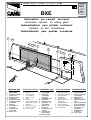 1
1
-
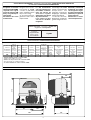 2
2
-
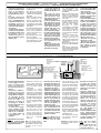 3
3
-
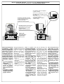 4
4
-
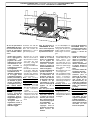 5
5
-
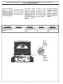 6
6
-
 7
7
-
 8
8
-
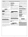 9
9
-
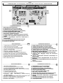 10
10
-
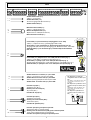 11
11
-
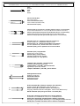 12
12
-
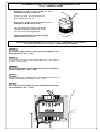 13
13
-
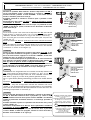 14
14
-
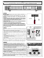 15
15
-
 16
16
-
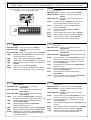 17
17
-
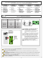 18
18
-
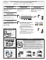 19
19
-
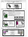 20
20
-
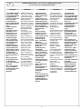 21
21
-
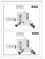 22
22
-
 23
23
-
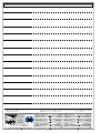 24
24


CAME BXE Manuale utente
- Tipo
- Manuale utente
- Questo manuale è adatto anche per
in altre lingue
- English: CAME BXE User manual
- français: CAME BXE Manuel utilisateur
- español: CAME BXE Manual de usuario
- Deutsch: CAME BXE Benutzerhandbuch
Documenti correlati
-
CAME ZBX7 Manuale utente
-
CAME BXE Manuale del proprietario
-
CAME BXE 241 Manuale utente
-
-
CAME BX Series Manuale utente
-
-
-
-
-

