
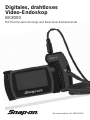
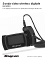
User Manual Part # ZBK8000
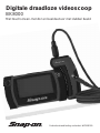
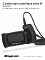
Digital Wireless Video Scope
BK8000
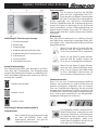
Features Touch Screen Display & Dual View Imager

Digital Wireless Video Scope
2 Snap-on
U.S. Patents 7,384,308; 7,431,619 B2; 7,581,988 B2; 7,584,534; 7,758,495 B2; 7,979,689; other patents pending. Industrial
Designs and other patents pending. Perceptron is a registered trademark of Perceptron, Inc. © 2011 Perceptron, Inc. All
Rights Reserved.Perceptron, Inc., 47827 Halyard Dr., Plymouth, MI 48170. www.perceptron.com
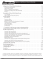
Table of Contents
General Safety Information......................................................................................... 3
Work Area Safety ................................................................................................................................. 3
Personal Safety .................................................................................................................................... 3
BK8000 Battery and A/C Power Supply.............................................................................................. 3
Video Scope Use and Care ................................................................................................................. 4
Service .................................................................................................................................................. 4
Specific Safety Information......................................................................................... 5
FCC Statement ..................................................................................................................................... 5
Video Scope Safety............................................................................................................................... 5
Getting Started............................................................................................................. 6
Description............................................................................................................................................ 6
Specifications........................................................................................................................................ 6
Standard Equipment ............................................................................................................................ 8
BK8000/A/C Power Supply Inspection and Set-Up........................................................................... 9
Assembling the Charger....................................................................................................................... 9
Charging the BK8000........................................................................................................................... 9
Cleaning Instructions............................................................................................................................ 10
Assembly .............................................................................................................................................. 10
To Connect the Imager to the Imager Handle..................................................................................... 10
Tool and Work Area Set-Up .......................................................................................11
Operating Instructions ................................................................................................11
Using the Imager................................................................................................................................... 11
Using the Display Unit........................................................................................................................... 11
Using the Display Unit Rear Camera................................................................................................... 12
Taking still pictures and videos with the Imager Handle.................................................................... 12
Using the kickstand and magnet.......................................................................................................... 12
User Button Interface ........................................................................................................................... 13
Battery Status Display........................................................................................................................... 13
Pairing BK8000 Viewer and Imager Handle....................................................................................... 16
Using the BK8000 Expansion Connectors......................................................................................... 16
Image Transfer to Computer using USB............................................................................................. 17
Transportation & Storage ...........................................................................................17
Maintenance Instructions ...........................................................................................17
Service and Repair .....................................................................................................17
Troubleshooting.............................................................................................................18
Warranty .......................................................................................................................18
Snap-on Service Center Locations............................................................................19

Digital Wireless Video Scope
3
Snap-on
General Safety Information
Read and understand all in structions.
Failure to follow all instructions listed
below may result in electric shock,
fire and/or serious personal injury.
SAVE THESE INSTRUCTIONS!
Work Area Safety
• Keepyourworkareacleanandwelllit.Cluttered
benches and dark areas may cause accidents.
• Donotoperateelectricaldevicesorvideoscope
tool in explosive at mospheres, such as in the
presenceofammableliquids,gases,orheavy
dust. Electrical devices or visual inspection
tools create sparks which may ignite the dust or
fumes.
• Do not use the video scope around corrosive
chemicals.
• Keep bystanders, children, and visitors away
while operating visual inspection tool. Do not let
visitors contact the unit.
Personal Safety
• Stayalert, watch what you are doing and use
common sense. Do not use video scope while
tired or under the inuence of drugs, alcohol,
or med ications. A moment of inattention while
op erating tools may result in serious per sonal
injury.
• Donotoverreach.Keepproperfootingandbal-
ance at all times. Proper footing and balance
enables better control of the tool in unexpected
situations.
• Use safety equipment.
Always wear eye protection
(users and bystandrs). Dust
mask, non-skid safety
shoes, hard hat, or hearing
protection must be used for appropriate condi-
tions.
• Useproperaccessories.Donotplacethisprod-
uct on any unstable cart or sur face. The product
may fall causing serious injury to a person or
serious damage to the product.
•Prevent object and liquid entry.
Never spill liquid of any kind on the
video dis play unit. Liquid increases
the risk of elec trical shock and
damage to the product.
• Donotusethisdeviceforpersonalormedical
use/inspection in any way.
• Theunitisnotshock-resistant.Donotuseitas
a hammer or drop it.
BK8000 Battery/ Power Supply
To reduce the risk of serious injury, read these pre-
cautions carefully before using the battery charger
or battery.
A/C Power Supply
• Do not probe A/C power supply with conduc-
tive objects. Shorting of battery terminals may
cause sparks, burns or electrical shock.
• Do not use A/Cpower supply if damaged. A
damaged A/C power supply increases the risk
of electrical shock.
• Use an appropriate power source. Do not
attempt to use a step-up transformer or an
engine generator. Doing so may cause damage
to the A/C power supply of the BK8000 resulting
inelectricalshock,reorburns.
• Do not allow anything tocover theA/C power
supply while in use. Proper ventilation is
required for correct operation of the A/C power
supply. Allow a minimum of 4” (10 cm) of clear-
ance around the charger for proper ventilation.
• Unplug the A/C power supply when not in
use. Reduces the risk of injury to children and
untrained persons.
• UnplugtheA/Cpowersupplyfromoutletbefore
attempting any maintenance or cleaning.
Reduces the risk of electrical shock.
• Do not use A/Cpower supply in a damp, wet
or explosive environment. Do not expose to
rain, snow or dirt. Contaminants and moisture
increase the risk of electrical shock.
• DonotopentheA/CpowersupplyorBK8000
housings. Have repairs performed only at
authorized locations. (see Snap-on Service
Center Location page 19).
• Do not carry the A/C power supply by power
cord. Reduces the risk of electrical shock.

Digital Wireless Video Scope
4 Snap-on
Battery Safety
The batteries in the BK8000 are NOT user replace-
able. Call your Service Center if you believe the
BK8000 battery is in need of service.
• Properly dispose of the BK8000. Exposure to
high temperatures can cause the battery to
explode, so do not dispose of in a re. Some
countries have regulations concerning battery
disposal. Please follow all applicable regula-
tions.
• Charge battery in temperatures above 32
degrees F (0 degrees C) and below 113 degrees
F (45 degrees C). Store BK8000 in tempera-
tures above -13°F (-25°C) and below 95°F
(35°C). Storage for a long time at temperatures
above 95°F (35°C) will reduce the capacity of
the BK8000. It is recommended to store the
BK8000 at 77°F (25°C) to maximize battery life.
Proper care will prevent serious damage to the
battery. Improper care of the battery may result
battery leakage, electrical shock and burns.
• IftheBK8000isdamaged,donotplugtheA/C
power supply into it. Do not attempt to charge.
• NeverdisassembletheBK8000unit.Thereare
no user-serviceable parts inside. Disassembling
the BK8000 may cause electrical shock or per-
sonal injury.
• Avoid contact with uids leaking from the
BK8000 unit. Fluids may cause burns or skin
irritation. Thoroughly rinse with water in case of
accidental contact with uid. Consult doctor if
uidcomesintocontactwitheyes.
Video Scope Use and Care
• Use video scope only as directed. Do not
operate the inspection unit unless the owner’s
manual has been read and proper training has
been com pleted.
• Do not immerse the handheld display unit in
water. Store in a dry place. Such measures
reduce the risk of electric shock and damage.
The imager head and the cable are water resis-
tant when the unit is fully assembled, but the
video display unit/handle is not.
• Do not use the camera if condensation forms
inside the lens. Let the water evap orate before
using again.
• DonotusetoolifON/OFFswitchisnotproperly
working. Any tool that cannot be controlled with
the switch is danger ous and must be repaired.
• Storeidleequipmentoutofthereachofchildren
and other untrained persons. Equipment is dan-
gerous in the hands of untrained users.
• Maintain the video scope with care. Properly
maintained tools are less likely to cause injury.
• Ifunitisdropped,checkforbreakageofparts,
and any other conditions that may affect the
tool’s operation. If dam aged, have the tool ser-
viced before using. Many accidents are caused
by poorly main tained tools.
• Use only accessories that are recommended
by the manufacturer for your tool. Accessories
that may be suitable for one tool may become
hazardous when used on another tool.
• Dry your hands before turning the unit ON or
OFF.
• Protect against excessive heat. The product
should be situated away from heat sources
such as radiators, heat registers, stoves or other
products (including ampliers) that produce
heat. Do not use the unit near moving machin-
ery or areas where the temperature will exceed
113°F (45°C).
Service
• Do not attempt to take any pieces of this unit
apart unless directed to by this manual.
• Follow instructions for changing accessories.
Accidents are caused by poorly maintained
equipment.
• Providepropercleaning.Donotuseacetoneto
clean the unit. Instead, use isopropanol.
• GentlycleantheLCDwithadrycloth.
• Stopusingtheunitifitstartssmokingoremit-
ting noxious fumes.
• Refervideoscopetoqualiedservicepersonnel
under any of the following conditions:
– If liquid has been spilled or objects have fall-
en into product;
– If product does not operate normally by fol-
lowing the operating instructions;
– If the product has been dropped or dam aged
in any way;
– When the product exhibits a distinct change
in performance.
If you have any questions regarding the service or
repair of this machine, call or write to the appropriate
repair center location (see "Snap-on Service Center
Locations page 19).

Digital Wireless Video Scope
5
Snap-on
Technical questions can be directed to our toll free
number at 1-877-765-7665 Monday through Friday
6:30 am to 5:00 pm Central Time (U.S. customers
only).
Specific Safety Information
Read this operator's manual carefully before using.
Failure to understand and follow the contents of this
manual may result in electrical shock, fire and/or se-
vere personal injury.
FCC Statement
This device complies with Part 15 of the FCC Rules.
Operation is subject to the fol lowing two conditions:
1. This device may not cause harmful inter ference.
2. This device must accept any interfer ence
received, including interference that may cause
undesired operation. NOTE! This equipment
has been tested and found to comply with
the limits for Class A digital devices, pursu-
ant to Part 15 of the FCC rules. These limits
are designed to provide reasonable protection
against harmful interference in a residential
installation. This equip ment generates uses
and can radiate radio frequency energy and, if
not in stalled and used in accordance with the
instructions, may cause harmful interference
to radio communications. However, there is no
guarantee that in terference will not occur in a
particular installation. If this equipment does
cause harmful interference to radio or television
reception, which can be de termined by turning
the equipment off and on, the user is encour-
aged to try to correct the interference by one or
more of the following measures:
– Reorient or relocate the receiving antenna.
– Increase the separation between the equip-
ment and receiver.
– Consult the dealer for help.
Use of shielded cable is required to comply with
Class A limits in Subpart B of Part 15 of the FCC
rules.
Do not make any changes or modifications to the
equipment.
This device complies with Part 15 of the FCC Rules
and with Industry Canada license-exempt RSS
standard(s). Operation is subject to the following two
conditions: (1) This device may not cause harm-
ful interference, and (2) This device must accept
any interference received, including reference that
may cause undesired operation. Note: Changes
or modification not expressly approved by the party
responsible for compliance could void the user's au-
thority to operate the equipment.
This Class A digital device complies with Canadian
ICES-003.
Video Scope Safety
• Donotplacetoolintoanythingoranywherethat
may contain a live electrical charge.
• FOR WALLS: For inspecting inside walls, be
sure to shut off the circuit breaker to the whole
house before using the tool behind any of the
walls
• FORPIPES:Ifyoususpectametalpipecould
contain an electrical charge, have a qualied
electrician check the pipe before using the
tool. Ground cir cuits, in some cases, can be
returned to cast iron pipes and cause them to
be charged.
• FOR AUTOMOBILES/HEAVY EQUIPMENT/
MOTORSPORTS: Be sure the auto mobile,
heavy equipment or motorsport equipment is
not running during inspection. Metal and liquid
under the hood may be hot. Do not get oil or gas
on the imager head. Exposure to petroleum-
based sub stances will eventually degrade the
im ager head covering.
• GENERALUSE:Donotuseanywheretheunit
may come into exposure with haz ardous chemi-
cals, electrical charges or moving parts. Such
situations may result in serious injury or death.
SAVE THESE INSTRUCTIONS!

Digital Wireless Video Scope
6 Snap-on
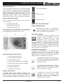
Getting Started
Description
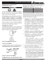
The BK8000 video scope displays live color video from an imaging sensor and lighting source connected to
a flexible dual view imager cable. The unit is capable of capturing still images and full-motion video, along
with audio. It can be used to look into tight spots and beam back real-time video to a color LCD. The magnet
accessory is included to attach to the imager head to provide application flexibility.
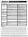
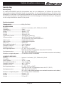
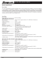
Specifications
Total Weight.................................1lb 10oz (800g)
DISPLAY UNIT:
Power Supply..................................Internal Li-Ion Battery, 3.7V, 2600 mAh, 9.6 watt-hours
Charge time .................................... 5 hours
Charger Input ..................................5V DC, 1. Amp
Length ............................................. 1.77" (45mm)
Width ...............................................7.2" (180mm)
Height ..............................................3.94" (100mm)
Built-in Camera ...............................3 megapixels, fixed focus
Screen Resolution ..........................480 x 272 RGB with LED backlight
4.3" (10.92 cm) Color Touchscreen LCD
Audio Input ......................................Built-in Microphone
Audio Output ...................................Built-in Speaker
Video Out ........................................NTSC/PAL
Run-time on battery .......................4 hours (approximately)
Wireless interface ..........................Wi-Fi - 802.11n
Wireless range ...............................33 ft (10m)
Operating Temperature ..................32°F to 104°F (0°C to 60°C)
(Batteries will not charge above 113°F (45°C))
Storage Temperature ..................... 14°F to 122°F (-20°C to 60°C )
59°F (15°C) is ideal for maximum battery life.
Relative Humidity.............................5% to 90% non-condensing
IMAGER HANDLE:
Power Supply..................................Internal Li-Ion Battery, 3.7V, 2600 mAh, 9.6 watt-hours
Charge time .................................... 5 hours
Charger Input ..................................5V DC, 1.Amp
Run-time on battery .......................4 hours (approximately)
Wireless interface ..........................Wi-Fi - 802.11n
Wireless range ...............................10m (33 ft)
Operating Temperature ..................32°F to 104°F (0°C to 60°C)
(Batteries will not charge above 113°F (45°C))
Storage Temperature ..................... 14°F to 122°F (-20°C to 60°C )
59°F (15°C) is ideal for maximum battery life.
Relative Humidity ...........................5% to 90% non-condensing
Length ............................................. 1.77" (45mm)
Width ...............................................3.07" (78mm)
Height ..............................................6" (152mm)

Digital Wireless Video Scope
7
Snap-on
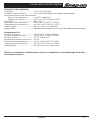
IMAGER:
Length ............................................. 36 in (0.91m) Dual View
Wireless Reception Range ............ 33 feet (10m) (unobstructed line-of-sight distance)
Forward Camera/Side Camera
Field of View ........................... approximately 52° diagonal
Optimal Focal Range .............0.5” to 12” (12cm to 30.5cm)
Resolution .......................................640 x 480
Operating Temperature ..................32°F to 104°F (0°C to 60°C)
Storage Temperature ..................... 14°F to 122°F (-20°C to 60°C)
Relative Humidity ...........................5% to 90% non-condensing
Water Resistance ........................... Imager to 10' (3m) water depth (when assembled)
A/C Power Supply:
Input Voltage ...................................100-240VAC, 50-60Hz 0.6Amp
Maximum inrush current ............... 30A @ 115VAC, 60A @ 230VAC
Output voltage ............................... 5V DC 2.6Amp Max
No Load Standby power ................<0.3W
Operating Temperature ..................32°F to 104°F (0°C to 40°C)
Storage Temperature ..................... 14°F to 167°F (-10°C to 75°C)
Relative Humidity ..........................20% to 80% non-condensing
NOTE! The charger and internal batteries are not compatible with any other Snap-on Li-Ion Batteries
and chargers.

Digital Wireless Video Scope
8 Snap-on
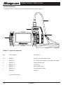
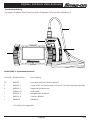
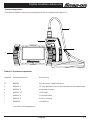
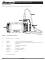
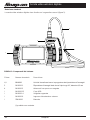
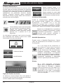
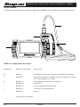
FIGURE 1: System Components
Key Stock Number Description
1,2 BK8000 Display Unit and Imager handle
3 BK8000-1 36" long, 8.5mm diameter 9-pin dual view imager
4 BK8000-5 Magnet retrieval tool
* BK6000-12 USB Cable
* BK8000-4 Blow molded case
* BK8000-6 External power supply
* ZBK8000 Manual
(*) product not shown
1
2
3
4
Standard Equipment
The Digital Wireless Video Scope comes with the following items (Figure 1):

Digital Wireless Video Scope
9
Snap-on
BK8000/A/C Power Supply Inspection and Set-
Up
Always wear eye protection to protect your eyes
against dirt and other foreign objects. Follow op-
erating instructions to reduce the risk of injury from
electrical shock.
Daily, before use, inspect the BK8000 and A/C Power
Supply and correct any problems. Set up charger
according to these procedures to reduce the risk of
injury from electrical shock, fire, and other causes and
prevent tool and system damage.
Before using the BK8000 for the first time, allow it
charge for at least 5 hours to ensure that the batteries
are fully charged.
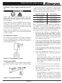
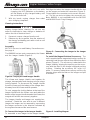
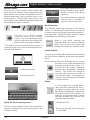
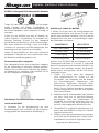
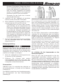
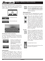
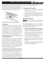
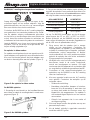
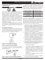
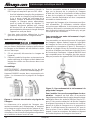
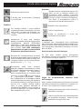
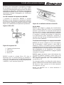
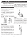
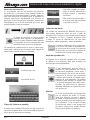
Assembling the Charger
The charger is supplied with a selection of adaptors
for use in multiple countries. Before first use, select
the appropriate adaptor for your country and attach it
to the charger (Figure 2).
Figure 2: Assembling the Charger
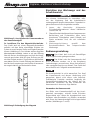
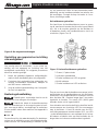
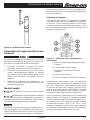
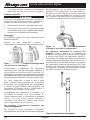
Charging the BK8000
1. Nest the Display unit and Imager Handle together
and insert the power supply cable as shown (Figure
3):
Figure 3: Charging the BK8000
2. Ensure that the correct adapter is fitted into the
charger and insert the charger into a suitable power
output. The LEDs on the Viewer and Imager Handle
will indicate the charging status as follows:
CHARGE STATUS LED STATUS
Not Charging LED is OFF
Pre-Charge LED is Amber
Charging LED is Red
Fully Charged LED is Green
Note: The BK8000 will only charge the batteries if
the temperature is between 0°C and 45°C (32°F
and 113°F). Outside of this temperature range the
BK8000 may continue to operate but the batteries will
not charge and the Charge Status LED will be off.
1. Make sure the charger is unplugged. Inspect
the power cord, charger and battery for dam-
ageormodications,orbroken,worn,missing,
misaligned or binding parts. If any problems are
found, do not use charger until the parts have
been repaired or replaced.
2. Clean any oil, grease or dirt from the equipment
as described in the Maintenance section, espe-
cially handles and controls. This helps prevent
the equipment from slipping from your grip and
allows proper ventilation.
3. Check to see that all warning labels and decals
on the BK8000 and A/C Power Supply are intact
and readable.
4. Select the appropriate location for the A/C
Power Supply before use. Check work area for:
– Adequate lighting.
– Flammable liquids, vapors or dust that may
ignite. If present, do not work in area until
sources have been identified and corrected.
The charger is not explosion proof and can
cause sparks.
– Do not use the device in wet or damp areas.
5. With dry hands, plug charger into the appropri-
ate power source.
6. When the battery is fully charged, the red LED
is replaced by a green LED.
– Once the battery is charged, it may remain
plugged into the charger until it is ready to
be used. There is no risk of over-charging
the battery. When the battery has been fully
charged, the charger automatically switches

Digital Wireless Video Scope
10 Snap-on
to retention charging. If the unit is on while
charging, the LED indicators on the battery
will not display a fully charged battery until
the unit is turned off.
7. With dry hands, unplug charger from outlet
once charging completes.
Cleaning Instructions
Unplug charger before cleaning. Do not use any
water or chemicals to clean charger or batteries to
reduce the risk of electrical shock.
1. If present, remove charger from the unit.
2. Remove any dirt or grease from the exterior of
the charger and battery pack with a cloth or soft
non-metallic brush.
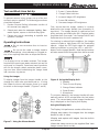
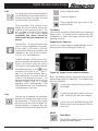
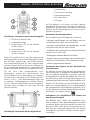
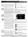
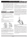
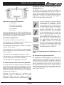
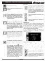
Assembly
NOTICE: Be sure to read Battery Precautions sec-
tion page 4.
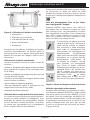
The BK8000 has two main components; the Viewer
and the Imager Handle (Figure 4).
Figure 4: Display Unit and Imager Handle
The Viewer and Imager Handle nest together for
storage, transportation and charging using a unique
locking feature. To disconnect the Imager Handle
from the Viewer, pull the bottom of the Imager Han-
dle away from the Viewer and lift upwards.
To nest, engage the locking feature at the top of the
Imager Handle with the Viewer case and rotate the
bottom of the Imager Handle towards the Viewer, the
magnet will hold the two securely together.
The Imager Handle and imager are supplied as-
sembled. Should the user wish to use a different
imager, the imager can be removed by unscrewing
the imager connector in the direction indicated by
the engraved arrow and the word remove.
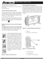
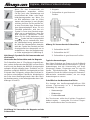
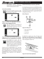
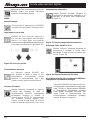
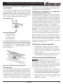
To Connect the Imager to the Imager Handle
To assemble a new imager to the Imager Handle,
first align the tab on the Imager Handle with the slot
on the imager and mate the connectors (Figure 5).
Finger-tighten the connector nut to secure the piec-
es. Do not use tools to tighten the connector nut.
Note: BK8000 is not compatible with the BK5500
and BK6000 Push-Fit style imagers.
Figure 5: Connecting the Imager to the Imager
Handle
To Install the Magnet Retrieval Accessory: The
unit is supplied with a magnet retrieval accessory for
retrieving small ferrous objects from difficult to reach
places (Figure 6). The accessory is attached to the
imager head by aligning the opening on the acces-
sory with the flats on the imager head and pushing
in-place. Rotating the accessory 90° locks it in
place. To remove, rotate the accessory until the clip
opening aligns with the flats on the imager and pull
to remove.
Figure 6: Installing Magnet

Digital Wireless Video Scope
11
Snap-on
Tool and Work Area Set-Up
To prevent serious injury, proper set-up of the tool
and work area is required. The following procedures
should be followed:
1 Review General Safety Information sec tion of
this manual (see page 4).
2. Check work area for:adequate lighting, am-
mable liquids, vapors or dust that may ignite.
3. Follow tool set-up according to specic tool
operator’s manual.
Operating Instructions
Do not use excessive force to in sert or
bend the cable.
Do not use the cable or imager head to
modify surroundings, clear pathways or clogged ar-
eas, or as anything other than an in spection device.
The Display Unit is not water resistant. The imager
head and its cover ing are water resistant, but are not
acid-proof or fireproof. Petroleum-based products
will ruin the imager cable’s protective plastic cover-
ing over time. Avoid submersing the imager head
into corrosive, oily places.
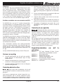
Using the Imager
To display images from the Imager Handle on the
viewing unit, both units must be turned on. If using
the Viewer to view or edit images, there is no need
to switch on the Imager Handle. (Figures 7 and 8).
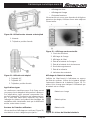
Figure 7: Using the Viewer Handle
First, ensure that the imager camera is correctly
attached to the Imager Handle (see Assembly in-
structions). The Imager Handle is switched on and
off by pressing and holding the ON / Capture button
for greater than 2 seconds – the Orange ON LED will
illuminate when the unit is powered on.
For viewing in reduced light conditions, the imager
camera includes a high-power LED for illuminating
objects. Adjust the LED light output for optimum
viewing conditions by using the LED + and LED –
buttons on the Imager Handle. Note that the buttons
will auto-repeat if held for greater than half a second.
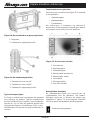
Figure 8: Using the Display Unit
To conserve batteries, the Imager Handle will auto-
matically switch off 20 minutes after the last button
press. The current status of the Imager Handle bat-
tery is displayed on the Display Unit display.
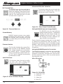
Using the Display Unit
The Display Unit performs a number of functions:
•Display and capture live images from the Imager
Handle as stills or video
•Display and capture still images from the built-in
rear camera.
•SelectthevideosourceonthesuppliedDualView
Imager camera (front or side)
1. Power / Capture Button
2. Charge Status Indicator
3. Increase Imager LED brightness
4. Power ON Indicator
5. Decrease Imager LED brightness
1. Speaker
2. Touch Screen Display
3. Charge Status Indicator
4. Power Button
5. Microphone

Digital Wireless Video Scope
12 Snap-on
•Play-backcapturedimagesandvideo
•Audioandtextualannotationofstillpictures(video
file naming)
•Deletestoredfiles
Using the Display Unit Rear Camera
The rear camera is used to capture high-resolution
(3 megapixels) still images. Pictures are best taken
when the object to be photographed is evenly lit from
the front. The system will not save a picture if there
is insufficient memory available.
Select the Rear Camera as the image source, (the
Display Unit will default to Still Image capture mode),
point the camera at the object to be photographed
and press the icon.
Taking still pictures and videos with the Imager
Handle
The BK8000 can store video and still images using
the Imager Handle as the source. Pictures and video
are captured and stored at a resolution of 640 x 480.
The original image is stored, the digital zoom func-
tion will have no affect on the stored image.
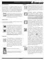
If using an imager with a dual camera,
select the Forward facing or Side fac-
ing camera then select the Video
capture or Still photograph mode. To
take a picture or start / stop a video
(depending on mode), briefly press
the ON / Capture button on the Im-
ager Handle. When taking a still
picture, the hourglass icon will dis-
play briefly to indicate that the picture
has been stored successfully. When
taking a video, the Display Unit will
show the
icon to indicate that
the video has started; when stop-
ping the video the Display Unit will
display the hourglass icon briefly in-
dicating video captured is displayed.
(Figure 9)
Figure 9: Imager and Camera Icons
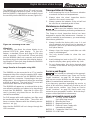
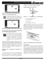
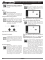
Using the kickstand and magnet
The kickstand has 3 positions to allow the user to
place the BK8000 at the optimum angle for viewing
and operating the BK8000 Viewer. In addition to the
kickstand, the BK8000 Display Unit has 4 magnets
located on the rear of the unit that will hold the unit
securely in place on a flat, ferrous surface such as
the side of a tool cabinet or car body panel. (Figure
10 and 11)
Figure 10: Using the Magnet and Kickstand
Figure 11: Using the Kickstand
1. Magnets
2. Kickstand in Closed Position
1. Kickstand at 90°
2. Kickstand at 45°
3. Kickstand in Closed Position

Digital Wireless Video Scope
13
Snap-on
Typical Applications
The Snap-on Video Scope is designed as a re mote
inspection device. Typical applications may include
automotive inspection, boat/aircraft inspection, etc.
It can be used for valve, cylinder bore, HVAC and a
rear-differential inspection, just to name a few.
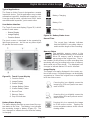
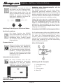
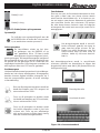
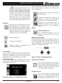
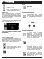
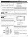
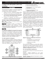
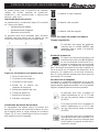
User Button Interface
The Touch Screen and display (Figure 12) is divid-
ed into 3 main areas:
• StatusDisplay
• ImageDisplay
• FunctionSelect
The touch screen is designed to be operated by
light finger pressure – do not use any other object
to operate the touchscreen.
Figure 12: Touch Screen Display
Battery Status Display
The status display provides an overview of the sys-
tem status to the user. The Battery Icon indicates
the remaining charge in battery (Figure 13). The
icon changes to indicate the user that the battery
is charging.
Battery Charging
Battery Full
Battery Empty
Figure 13: Battery Status Icons
Record Time
The record time indicator indicates
that the BK8000 is recording video or
audio and the length of the recording.
Memory Status
The available memory space in the
BK8000 internal memory or an inserted
Micro SD memory card is shown as a
percentage of the original size. The ac-
tual number of still pictures or video recording time
remaining will vary according to the size of memory
device and mix of files stored. The displayed icon
changes to indicate that an SD card is inserted.
Image Display
The image is normally displayed in the center sec-
tion of the screen. Displayed images can be digitally
zoomed up to 2 times the original size or expanded
to fill the entire screen.
Pressing this icon digitally zooms the
image in by 25% each press to a maxi-
mum of 200%.
Pressing this icon digitally zooms the
image out by 25% each press to a mini-
mum of 100%
Pressing this icon expands the image
to fill the entire screen. Tapping the
screen anywhere returns to the normal
viewing mode.
1. Function Select
2. Image Display
3. Status Display
4. Imager Battery Status
5. Viewer Battery Status
6. Record Time
7. Memory Status
8. Pop-Out Indicator

Digital Wireless Video Scope
14 Snap-on
Function Select
Pressing one of the function select buttons will
either step into another screen presenting addi-
tional functions or will 'pop' out an additional set of
buttons allowing the user to quickly select a par-
ticular function. Those buttons that 'pop out' can
be identified by the additional light grey background
surrounding the button as shown:
The back icon is used in various
screens to move to the previous
screen. The user can always return
to the home screen by pressing this
button until it is no longer available.
The confirm screen is used in various screens to
confirm that the user is sure that the desired func-
tion has been selected.
Confirms the action
Cancels the action
Figure 14: On-Screen Keyboard
The On-Screen keyboard (Figure 14)is used when
text entry is required such as renaming a file or an-
notating a picture.
This button switches to an ad-
ditional keyboard layout which
includes numbers and special
characters.
This button exits the keyboard
and the user is prompted to
confirm or cancel the action.
Mode Selection
The BK8000 Display Unit operates in two distinct
modes: Live Mode and Playback Mode. Live mode
is used for viewing live images and capturing still pic-
tures and video. Playback mode is used for viewing
and editing recorded images and videos.
When in Live mode, pressing the
Playback Mode icon selects Playback
mode. The Function select buttons will
change according to the selected mode.
Playback Mode
The user is presented with a thumbnail view showing
the files that are available, when entering Playback
mode.
If there are too many files to display on one screen,
the arrow icons scroll backwards and
forwards through the list of files. Se-
lect the file to be viewed / edited by
pressing the appropriate thumbnail
picture. The screen will change to
show the still image or first frame of
the selected video. The desired op-
eration is selected using the following
Function buttons.
Delete
If a still image with an audio attach-
ment has been selected, the user is
prompted to delete either the audio
attachment (if available) or both the au-
dio and picture file; then confirm. If a
video file, or still picture with no audio
has been selected, then only the com-
plete file may be deleted.
Delete Entire File
Delete just the audio note, the picture
is not deleted.

Digital Wireless Video Scope
15
Snap-on
Edit
For still pictures, the edit menu allows a
user to Rename or Annotate (audio or
textual) the picture; for video, only the
rename function is available.
Text Annotation (Still pictures only).
Allows the user to add a textual an-
notation to the selected picture. The
text is added to the top of the picture
as displayed on the screen. Once
confirmed, this action cannot be
undone and the text cannot be re-
moved.
Rename File. This function allows the
user to append additional characters
to the name of the video or still file.
Note that the following characters are
available to the user for this function:
A-Z, a-z, 0-9, and underscore.
Audio Annotation (Still pictures only).
Records an audio annotation to the se-
lected still picture using the built-in
microphone. Recording starts immedi-
ately upon selecting. Press
to stop
recording. This action is not avail-
able if a still picture already has an
audio annotation; to record a new an-
notation, first delete the old one. For
best results talk towards the front of the
BK8000 Display Unit in a normal
speaking voice approximately 0.6m
(2ft) away from the unit. Maximum re-
cording length is one hour.
Play
This function is available for both video
files and still images with attached au-
dio annotations. Pressing this button
will start to play the video or audio file.
During playback, a progress bar indi-
cates the current position within the file.
Pause Playback mode
Continue Playback
Stops playback and goes back to the
thumbnail view.
Live Mode
In live mode an image is displayed from the selected
video source. This image can be captured as a still
photograph or video file (Imager Handle only) de-
pending on mode.
Image Source Selection
If there is no paired Imager Handle detected, the fol-
lowing screen will be displayed (Figure 15).
Figure 15: Image Source Selection Display
Note: the display until will continue to search for the
paired imager until it is detected. The following op-
tions are available:
Selects the forward looking camera on
the imager
Selects the side view camera on the im-
ager. Valid only for dual view imagers
Selects the rear BK8000 Display Unit.
Note that this camera supports still pic-
tures only.
MENU
Tools Menu
The BK8000 settings tools are found by
pressing the tools button.

Digital Wireless Video Scope
16 Snap-on
Set Time and Date
The BK8000 uses the time and date to
record what time that a still picture or
video was captured. After pressing this
function the BK8000 presents the user
with the Time and Date and an Up and
a Down arrow. (Figure 16)
Figure 16: Time and Date Icon
Format Memory
BK8000 internal memory may require
formatting from time to time. Selecting
this function and confirming will result
in all data being removed from internal
memory.
Firmware Version
This function displays the current firm-
ware versions of the BK8000 Display
Unit, Imager Handle and communica-
tion module. NOTE: Firmware updates
may be provided pre-loaded onto a mi-
cro SD card or supplied electronically
by download or email.
Auto Shut Down
This function allows the user to config-
ure auto shut down ranging from
disable to 30 minutes. (Figure 17)
Figure 17: Auto Shut Down Display
Video Out NTSC/PAL Selection
The function allows the user to select the
desired video output format. Press the
back arrow to exit. (Figure 18)
Figure 18: Video Output Format Display
Pairing BK8000 Viewer and Imager Handle
The BK8000 can only work with one
Imager Handle at a time. The BK8000
Display Unit and Imager Handle are
shipped to the user as a pair. To use
the Display Unit with a different Im-
ager Handle it must be paired.
Ensure that the Imager Handle that is to be paired
is switched on and that the LEDs are visible. The
Display Unit will display a list of all available Imager
Handles. Select the desired imager handle from the
list. The LEDs on the Imager Handle will blink to con-
firm pairing.
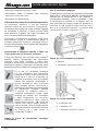
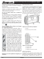
Using the BK8000 Expansion Connectors
The BK8000 expansion connectors are located be-
hind a flexible protective cover. To use any of the
expansion connectors, first open the cover and fol-
low the instructions below. After use, please replace
the protective cover.
Micro SD socket
Figure 19: SD Socket
1. Protective Cover
2. USB-mini
3. Video Out
4. Micro SD

Digital Wireless Video Scope
17
Snap-on
The BK8000 will accept a Micro SD card (not sup-
plied) for storage of pictures or video. To use, ensure
that the BK8000 is switched off and carefully insert
the card fully into the BK8000 as shown (Figure 20) :
Figure 20: Installing an SD Card
Video Out
The BK8000 can direct the viewer display to an
external NTSC/PAL video display. To use this
feature, a standard 3.5mm jack plug to RCA plug
cable is required. Fully insert the 3.5mm jack plug
into the BK8000 video-out connector and connect
the phone plug to the desired video display device.
Inserting the 3.5mm jack plug disables the BK8000
LCD display and touchscreen.
Image Transfer to Computer using USB
The BK8000 can be connected to a PC to transfer
image and video files using the supplied USB cable;
insert the small connector into the BK8000 and the
larger end into a computer. Depending on the oper-
ating system , the computer may inform the user that
a device is attached. The view unit LCD screen will
shut off while attached to the computer.
The BK8000 will appear as an external drive to the
user allowing pictures and videos to be transferred
to and from the BK8000. Note that if a Micro SD
card is inserted, only those files on the Micro SD
card will be available.
For Still images with audio captions, two files must
be transferred to the same folder. These files will
have a common filename with the following two ex-
tensions: .avi .jpg
Note that the BK8000 will not charge through the
USB connector.
Transportation & Storage
1. Avoid exposing the unit to continuous vi bration
or extreme hot and cold temper atures.
2. Always store the visual inspection device
in doors in the case it came with.
3. Always remove the batteries if the unit will not
be used for an extended period of time.
Maintenance Instructions
Make sure the batteries have been re-
moved from the unit before performing maintenance.
The Snap-on visual inspection device has been
designed to require little maintenance. However, in
order to maintain its performance, you must al ways
follow these guidelines:
1. Always handle the device with care. It is not
shock-resistant and should not be banged or
dropped. Treat it as you would any other sensi-
tive optical device.
2. Always clean the imager head after use with
soap or mild detergent.
3. Use only alcohol swabs to clean the con-
nections.
4. Avoid rubbing too hard on the LCD. After use,
wipe the display clean gently with a dry cloth.
5. Do not disassemble this device beyond what
is shown in the manual. Doing so will void your
warranty.
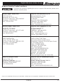
Service and Repair
Tool should be returned to the appropri-
ate repair center locations (see "Snap-on Service
Center Locations" on page 19). All repairs made
by Snap-on service facil ities are warranted against
defects in material and workmanship.
If you have any questions regarding the service or
repair of this machine, please call or write to one of
the eight service centers (see "Snap-on Service
Center Locations" on page 19) that is most con-
venient to your geographic location. Web site: buy1.
snapon.com/snaponstore/customer.asp
User serviceable repair parts
BK8000-1 36" long, 8.5mm diameter,
9-pin dual view imager
BK8000-4 Blow Molded Case
BK8000-5 Magnet Retrieval tool
BK8000-6 External Power Supply with
international adapters
BK5500-8 Composite Video Out Cable
BK6000-12 USB Cable

Digital Wireless Video Scope
18 Snap-on
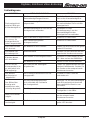
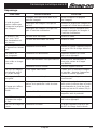
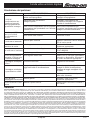
SYMPTOM POSSIBLE REASON SOLUTION
Display Unit does not
display image from
imager handle
The imager is not inserted into the
imager handle
Connect imager securely to imager
handle
Imager handle not switched on Switch imager handle on & pair
with Display Unit
Imager handle is not paired with Display
Unit
Use Settings Menu to pair
imager handle with Display Unit
LCD screen is black,
but Display Unit is
ON
USB cable is inserted Remove cable
Video out cable is inserted Remove cable
Unit will not switch on Battery is very low Charge unit until Green charge
LED illuminates.
Battery does not hold
a charge
Faulty battery Return unit to appropriate service
center location.
Units will not charge
Power supply is not plugged in. Connect power supply to AC
supply and to BK8000
Battery is too hot Allow unit to cool
LED on imager is ON
but no image
Broken video signal wire Test with second imager if
available. Return to appropriate
service center location
Image on display is
frozen
Processor locked up Cycle power
Image on display is
breaking up or jerky
Imager handle out of range of Display
Unit
Move imager handle and Display
Unit within recommended range of
30 feet (10m)
Interference on radio Change channels on other radio
devices near by
Charging LEDs flash
red/green
Faulty battery Return unit to appropriate service
center location.
Charging LED glows
amber
Battery is low Charge until Green LED illuminates
Troubleshooting
Warranty
Limited Two (2) Year Warranty Snap-on Tools Company (the “Seller”) warrants only to the original purchaser that under normal use, care and
service, the Equipment (except as otherwise provided herein) shall be free from defects in material and workmanship for two years from the
date of original invoice. SELLER’S OBLIGATIONS UNDER THIS WARRANTY ARE LIMITED SOLELY TO THE REPAIR OR, AT SELLER’S
OPTION,REPLACEMENTOFEQUIPMENT OR PARTSWHICHTO SELLER’SSATISFACTIONARE DETERMINED TO BE DEFECTIVE AND
WHICHARENECESSARYINSELLER’SJUDGMENT,TORETURNTHISEQUIPMENTTOGOODOPERATINGCONDITION.NOOTHERWAR-
RANTIES,EXPRESSORIMPLIEDORSTATUTORY,INCLUDINGWITHOUTLIMITATIONANYIMPLIEDWARRANTYORMERCHANTABILITY
ORFITNESSFORAPARTICULARPURPOSE,SHALLAPPLYANDALLSUCHWARRANTIESAREHEREBYEXPRESSLYDISCLAIMED.This
warranty does not cover (and separate charges for parts, labor and related expenses shall apply to) any damage to, malfunctioning,in operability
or improper operation of the Equipment caused by, resulting from or attributable to (A) abuse, misuse or tampering;(B) alteration, modification or
adjustment of the Equipment by other than Seller’s authorized representatives; (C) installation, repair or maintenance (other than specified operator
maintenance) of the Equipment or related equipment, attachments, peripherals or optional features by other than Seller’s authorized representatives;
(D) improper or negligent use,application, operation, care, cleaning, storage or handling; (E) fire, water, wind, lightening or other natural causes; (F)
adverse environmental conditions, including, without limitation, excessive heat, moisture, corrosive elements, or dust or other air contaminants, radio
frequency interference, electric power failure, power line voltages beyond those specified for the Equipment, unusual physical, electrical or electro-
magnetic stress and/or other condition outside of Seller’s environmental specifications;(G) use of Equipment in combination or connection with other
equipment, attachments, supplies or consumable not manufactured or supplied by Seller; or (H) failure to comply with any applicable federal, state or
local regulation,requirement or specification governing emission analyzers and related supplies or consumables. Repairs or replacements qualifying
under this Warranty will be performed on regular business days during Seller’s normal working hours within a reasonable time following purchaser’s
request. All requests for Warranty service must be made during the stated warranty period. This Warranty is nontransferable.

Digital Wireless Video Scope
19
Snap-on
Snap-on Service Center Locations
If you have any questions regarding the service or repair of this machine, please call or
write the nearest location:
Eastern Repair Center (USA)
6320 Flank Drive
Harrisburg, PA 17112 USA
Toll Free # - (USA only): (800)-848-5067
Telephone: (717) 652-7914
Fax: (717) 652-7123
Snap-on Tools (Australia) Pty Ltd
National Distribution Centre
Unit 6/110 Station Road
PO Box 663
Sven Hills, NSW 1730 Australia
Telephone: (61) 2-9837-9100
Fax: (61) 2-9624-2578
email: sota.webmast[email protected]
Northern Repair Center (USA)
3011 E. RT 176, Dock 8
Crystal Lake, IL 60014
Toll Free # - (USA only): (877) 777-4412
Telephone: (815) 479-6850
Fax: (815)479-6857
Snap-on Tools Singapore PTE, Ltd.
25 Tagore Lane #01-01
Singapore 787602
Telephone: +(65) 6451-5570
Fax: +(65) 6451-5574
email: [email protected]
Internet: http://snapon.com.sg
Western Repair Center (USA)
3602 Challenger Way
Carson City, NV 89706 USA
Toll Free # - (USA only): (888) 762-7972
Telephone: (775) 883-8585
Fax: (775) 883-8590
Snap-on Tools Japan, K.K.
Snap-on, Bahco, and Cartec
Also serving Taiwan and Micronesia
(Distribution Center and Technical Repair Center)
2-1-6 Shinkiba, Koto-ku,
Tokyo,136-0082JAPAN
Telephone: +81 3 5534 1280
Fax: +81 5534 1284
email:SOJ[email protected]
OEM, National Accounts, GSA
Distribution: +81 3 5534 1300
Industrial: +81 3 5534 1281
BAHCD: +81 3 5534 1301
Technical Repair Center: +81 3 5534 1289
Snap-on UK Repair Centre
Snap-on Tools, Ltd.
Telford Way, Kettering
Northants, NN16 8UN ENGLAND
Telephone: 01536 413855
Fax: 01536 410740
Snap-on Tools of Canada Repair Center
7403 48th St. S.E.
Calgary, Alberta T2C 4H6 CANADA
Toll Free #: (866) 824-0525
Telephone: (403) 720-4525
Fax: (403) 720-4524
email: [email protected]
Snap-on is a trademark of Snap-on Incorporated. © 2011 Snap-on Incorporated. All Rights Reserved. Printed in USA.

Digital Wireless Video Scope
20 Snap-on
La pagina si sta caricando...
La pagina si sta caricando...
La pagina si sta caricando...
La pagina si sta caricando...
La pagina si sta caricando...
La pagina si sta caricando...
La pagina si sta caricando...
La pagina si sta caricando...
La pagina si sta caricando...
La pagina si sta caricando...
La pagina si sta caricando...
La pagina si sta caricando...
La pagina si sta caricando...
La pagina si sta caricando...
La pagina si sta caricando...
La pagina si sta caricando...
La pagina si sta caricando...
La pagina si sta caricando...
La pagina si sta caricando...
La pagina si sta caricando...
La pagina si sta caricando...
La pagina si sta caricando...
La pagina si sta caricando...
La pagina si sta caricando...
La pagina si sta caricando...
La pagina si sta caricando...
La pagina si sta caricando...
La pagina si sta caricando...
La pagina si sta caricando...
La pagina si sta caricando...
La pagina si sta caricando...
La pagina si sta caricando...
La pagina si sta caricando...
La pagina si sta caricando...
La pagina si sta caricando...
La pagina si sta caricando...
La pagina si sta caricando...
La pagina si sta caricando...
La pagina si sta caricando...
La pagina si sta caricando...
La pagina si sta caricando...
La pagina si sta caricando...
La pagina si sta caricando...
La pagina si sta caricando...
La pagina si sta caricando...
La pagina si sta caricando...
La pagina si sta caricando...
La pagina si sta caricando...
La pagina si sta caricando...
La pagina si sta caricando...
La pagina si sta caricando...
La pagina si sta caricando...
La pagina si sta caricando...
La pagina si sta caricando...
La pagina si sta caricando...
La pagina si sta caricando...
La pagina si sta caricando...
La pagina si sta caricando...
La pagina si sta caricando...
La pagina si sta caricando...
La pagina si sta caricando...
La pagina si sta caricando...
La pagina si sta caricando...
La pagina si sta caricando...
La pagina si sta caricando...
La pagina si sta caricando...
La pagina si sta caricando...
La pagina si sta caricando...
La pagina si sta caricando...
La pagina si sta caricando...
La pagina si sta caricando...
La pagina si sta caricando...
La pagina si sta caricando...
La pagina si sta caricando...
La pagina si sta caricando...
La pagina si sta caricando...
La pagina si sta caricando...
La pagina si sta caricando...
La pagina si sta caricando...
La pagina si sta caricando...
La pagina si sta caricando...
La pagina si sta caricando...
La pagina si sta caricando...
La pagina si sta caricando...
La pagina si sta caricando...
La pagina si sta caricando...
La pagina si sta caricando...
La pagina si sta caricando...
La pagina si sta caricando...
La pagina si sta caricando...
La pagina si sta caricando...
La pagina si sta caricando...
La pagina si sta caricando...
La pagina si sta caricando...
La pagina si sta caricando...
La pagina si sta caricando...
La pagina si sta caricando...
La pagina si sta caricando...
La pagina si sta caricando...
La pagina si sta caricando...
La pagina si sta caricando...
La pagina si sta caricando...
La pagina si sta caricando...
La pagina si sta caricando...
La pagina si sta caricando...
La pagina si sta caricando...
La pagina si sta caricando...
La pagina si sta caricando...
-
 1
1
-
 2
2
-
 3
3
-
 4
4
-
 5
5
-
 6
6
-
 7
7
-
 8
8
-
 9
9
-
 10
10
-
 11
11
-
 12
12
-
 13
13
-
 14
14
-
 15
15
-
 16
16
-
 17
17
-
 18
18
-
 19
19
-
 20
20
-
 21
21
-
 22
22
-
 23
23
-
 24
24
-
 25
25
-
 26
26
-
 27
27
-
 28
28
-
 29
29
-
 30
30
-
 31
31
-
 32
32
-
 33
33
-
 34
34
-
 35
35
-
 36
36
-
 37
37
-
 38
38
-
 39
39
-
 40
40
-
 41
41
-
 42
42
-
 43
43
-
 44
44
-
 45
45
-
 46
46
-
 47
47
-
 48
48
-
 49
49
-
 50
50
-
 51
51
-
 52
52
-
 53
53
-
 54
54
-
 55
55
-
 56
56
-
 57
57
-
 58
58
-
 59
59
-
 60
60
-
 61
61
-
 62
62
-
 63
63
-
 64
64
-
 65
65
-
 66
66
-
 67
67
-
 68
68
-
 69
69
-
 70
70
-
 71
71
-
 72
72
-
 73
73
-
 74
74
-
 75
75
-
 76
76
-
 77
77
-
 78
78
-
 79
79
-
 80
80
-
 81
81
-
 82
82
-
 83
83
-
 84
84
-
 85
85
-
 86
86
-
 87
87
-
 88
88
-
 89
89
-
 90
90
-
 91
91
-
 92
92
-
 93
93
-
 94
94
-
 95
95
-
 96
96
-
 97
97
-
 98
98
-
 99
99
-
 100
100
-
 101
101
-
 102
102
-
 103
103
-
 104
104
-
 105
105
-
 106
106
-
 107
107
-
 108
108
-
 109
109
-
 110
110
-
 111
111
-
 112
112
-
 113
113
-
 114
114
-
 115
115
-
 116
116
-
 117
117
-
 118
118
-
 119
119
-
 120
120
-
 121
121
-
 122
122
-
 123
123
-
 124
124
-
 125
125
-
 126
126
-
 127
127
-
 128
128


in altre lingue
- English: Snap-On BK8000 User manual
- français: Snap-On BK8000 Manuel utilisateur
- español: Snap-On BK8000 Manual de usuario
- Deutsch: Snap-On BK8000 Benutzerhandbuch
- Nederlands: Snap-On BK8000 Handleiding
Documenti correlati
Altri documenti
-
Datalogic Lynx 00N0LD-1N0-MEN0 Manuale utente
-
Datalogic SKORPIO Compact Hand-Held Mobile Computer Manuale utente
-
Rothenberger Inspection camera ROSCOPE i2000 Modul 25/16 + TEC Manuale utente
-
Datalogic 942500002 Manuale utente
-
Datalogic Memor 10 Manuale utente
-
Datalogic Falcon X4 Manuale utente
-
-
Pulsar Helion XP38 Instructions Manual
-
RIDGID micro CA-100 Manuale utente
-
LG DP481B Manuale utente