Rockford Fosgate PPS4-6 Manuale del proprietario
- Categoria
- Altoparlanti per auto
- Tipo
- Manuale del proprietario
Questo manuale è adatto anche per

LJ
N
Pro
Speakers
PPS4-6
PPS4-8
Serial
Number:
PPSB-6
PPSB-8
Installation
&
Operation
Installation
et
fonctionnement
lnstalacion
y
funcionamiento
Einbauund
Betrieb
lnstala~ao
e
Funcionamento
Date
of
Purchase:

.LhCAUTION:
SAFETY
Before
installation,
disconnect
the
battery
negative
(-)terminal
to
prevent damage
to
the
unit, fire
and/or
possible injury.
PRACTICE
SAFE
SOUND™
Continuous exposure
to
sound pressure
levels over
I
OOdB
may
cause permanent hearing loss.
High
powered auto sound systems
may
produce sound pressure
levels well
over
130dB.
Use common
sense and practice safe sound.
CARTON
CONTENTS
(I)
Pc
Punch
Series
Mid
Range Speakers
•
(I)
Pair of grilles/trim rings
• Mounting Hardware
INSTALLATION
CONSIDERATIONS
Before beginning any installation,
follow
these simple rules:
I.
Be
sure
to
carefully
read and understand
the
instructions before attempting
to
install
these speakers.
2.
For safety, disconnect
the
negative
lead
from
the
battery prior
to
beginning the
installation.
3.
For easier assembly, we suggest you run
all
wires prior
to
mounting your speakers
in
place.
4. Use
high
quality connectors for a
reliable
installation and
to
minimize
signal
or
power
loss.
5.
Think
before
you
drill!
Be
careful
not
to
cut
or
drill
into gas tanks,
fuel
lines,
brake
or
hydraulic lines, vacuum
lines
or
electrical wiring when working
on
any
vehicle.
If
installation
in
a boat, take care
not
to
cut
or
drill
through
the
main
hull.
6.
Never run wires underneath the vehicle. Running
the
wires inside
the
vehicle
or
hull
area provides the best protection.
7.
Avoid running wires over
or
through sharp edges. Use rubber
or
plastic
grommets
to
protect
any
wires routed through metal, especially the firewall.
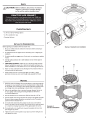
MOUNTING
I . Determine where
the
speakers
will
be mounted. Ensure an area large enough for
the
speaker
to
mount evenly.
Be
sure
that
the
mounting location
is
deep enough
for
the
speaker
to
fit;
if
mounting
in
a door,
operate
all
functions (windows, locks,
etc.) through their entire operating range
to
ensure
there
is
no obstruction.
2. Refer
to
the
specification chart
to
determine
the
proper diameter
hole
to
cut
for your speaker model. Cutting and mounting templates can be found
at
www
.rockfordfosgate.com.
3. Mark
the
locations for
the
mounting screws.
Drill
the
holes with a
I
/8"
bit.
4. Feed
the
speaker wires through the
cutout
and connect
to
the
speaker terminals.
Be
sure
to
observe proper polarity when connecting
the
wires. The speaker's
positive terminal
is
indicated with a
"+".
Sa.
On
models with slotted holes,
fit
the speaker into
the
cutout and
install
the
screws
in
the slots at
the
top
and bo
tto
m.
This
will
allow
you
to
ro
ta
te
the speak-
er
to
match the remaining mounting holes.
When
aligned, tighten
the
screws.
Sb
.
On
models with a trim ring, fit the trim
ring
over
the
speaker and mount into
place using four
(4)
screws.
6. Tighten
the
screws until
the
speaker
is
snug
in
place
to
prevent rattling.
Do
not
over
tighten the screws.
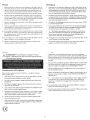
Example
of
standard
door
installation
Example
of
rear
deck
installation
l

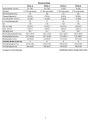
SPECIFICATIONS
PPS4-6
PPS8-6 PPS4-8
PPS8-8
Nominal
Diameter-
inch
(mm)
6.5"
(165)
6.5"
(165)
8"
(203)
8"
(203)
Description
6.5"
Mid
range
speaker
6.5"
Mid
range
speaker
8"
Mid
range
speaker
8"
Mid
range
speaker
Nominal
Impedance
(ohms)
40
80
40
80
Frequency
Response
(Hz)
85-5KHz
87-5KHz
80
-
5KHz
82-5KHz
Voice
Coil
Diameter-
inch
(mm)
1.53
"
(38.7)
1.53"
(38.7)
2.0"
(49.5)
2.0"
(49.5)
Fs
-
Free
Air
Resonance
(Hz)
85
87
80
82
Qts
0.
36
0.45
0.34 0.50
Vas-
cu.
ft.
(Liter)
0.24
(6.9)
0.24
(6.9)
0.54
(15.2)
0.54
(15.2)
Xmax-
inch
(mm)
0.
04(1
.
0)
0.
04(1.0)
0.
04(1
.
0)
0.
04(1
.
0)
SPL
(dB
@ 1
wl1
m)
92.5
91.5
94.5 93.0
Power
Handling-Watts
(RMS
I
Peak)
100WI200W
100
WI
200
W
125
WI
250
W
125
WI
250
W
Mounting
Diameter-inch
(mm)
5.67
"
(144.00)
5.67"
(144.00)
7.12"
(180.87)
7.12
"
(180.87)
Mounting
Depth-inch
(mm)
2.
24
(56
.
80)
2.
24
(56.80)
2.91
(74.00)
2.
91
(74.00)
Includes
Grille/Trim
ring
y
y y y
Trim
Ring
Diameter-inch
(mm)
6.69
(170.00)
6.69
(170.00)
8.35
(212.00)
8.35
(212.00)
Trim
Ring
Height-inch
(mm)
0.66
(16.84)
0.66
(16.84)
0.92
(23.24
)
0.92
(23.24)
See figues on
following
pages.
specifications
subject
to
change without notice
3

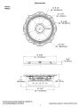
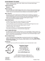
PPS4-6
PPSB-6
SPECIFICATIONS
0
669"
(0
170.00mm)
I
/
~
~
~
0
6.16"
(0
156.50mm)
~
0 0.18"
(0
4.50mm)
0
6.22"
(0
158.00mm)
0
6.61"
(0
168.00mm)
r-
~
0.66"
(16.84mm)
~~'-j$~~,~~
·
~c:!:!~~rr~ll~~
-1/
~
"
.
~r
};•n~Ell
2.24"
\
~
~
~
~
I
2.44"
(56.80mm)
(62.1
Omm)
~
u
~~
(g
[}={].
0 5.67"
(0
144.00mm)
Cutting
and
mounting
templates
available at:
www.rockfordfosgate.com/rftech.
Specifications subject
to
change
without
notice.
4

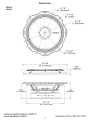
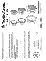
PPS4-8
PPSB-8
r
2.91"
(73.83mm)
Cutting
and
mounting
templates
available at:
www.rockfordfosgate.com/rftech.
SPECIFICATIONS
0 8.35"
(0
212.00mm)
e
H.
0
7.12"
(0
180.87mm)
5
0
7.8"
(0
198.00mm)
0
0.18"
(0
4.50mm)
0
7.8"
(0
198.00mm)
0
8.27"
(0
21
O.OOmm)
l
3.12"
0.92"
(23.24mm)
(79.25mm)
Specifications
subject
to
change
without
notice.

Fran~ais
~
MISE
EN GARDE
:
avant
d'entamer
!'installation,
deconnectez
Ia
•
broche
negative (-)
de
Ia
batterie
pour
eviter
tout
risque
de
blessures,
d'incendie
ou
de
dommages
a
l'appareil.
PRATIQUEZ
UNE
ECOUTE
SANS
RISQUESHD
Une
exposition
continue
a
des
niveaux
de
pression
acoustique
superieurs
a
I
00
dB
peut
causer
une
perte
d'acuite auditive
permanente.
Les
systemes
audio
de
forte
puissance
pour
auto
peuvent
produire
des
niveaux
de
pression
acoustique
bien
au-dela
de
130
dB.
Faites
preuve
de
bon
sens
et
pratiquez
une
ecoute
sans
risques
Espaiiol
A\
PRECAUCION:
Antes
de
Ia
instalaci6n,
desconecte
el
terminal
~
negativo
de
Ia
bateria
(-)para
prevenir
dai\o
a
Ia
unidad,
incendio
y/o
posibles
lesiones.
Wll!!l...wi
..
II!IIIIIW!!--
rnM'-
I
1\,tUC
CL
~VI"'ILIV
~CUUnV
El
contacto continuo
con
niveles
de
pr
esi
on
de
sonido superiores a
100
dB
puede
causar
Ia
perdida permanente
de
Ia
audicion. Los sistemas
de
sonido para
autom6viles
de
alta
potencia pueden producir
niveles
de
presion
de
sonido
superiores a
los 130
dB
. Use su sentido
comun
y practique
el
sonido seguro.
Consideraciones
para
Ia instalacion
Antes
de
comenzar
cualquier instalacion,
siga estas
simples
normas:
I.
Asegurese
de
leer
cuidadosamente y
de
entender
las
instrucciones antes
de
tratar
de
instalar
estos
altavoces.
2.
Por
seguridad,
desconecte
el
conductor
negativo
de
Ia
bateria antes
de
comenzar
Ia
instalaci6n.
3.
Para facilitar el
montaje, sugerimos que tienda
todos
los cables
antes
de
montar
sus
altavoces en su sitio.
4.
Utilice
conectores
de
alta calidad
para
tener
una instalaci6n
confiable
y para
reducir
al
mfnimo
las
perdidas
de
seiial
o
de
potencia.
5. iPiense
siempre antes
de
perforar! Tenga cuidado
de
no
cortar
ni
perforar
en
tan-
ques
de
combustible, tuberfas
de
combustible, frenos o
hidraulicas,
tuberfas
de
vado
o
cableado electrico al
trabajar
en
un vehfculo.
Si
Ia
instalaci6n se hace en
un
bote,
tenga cuidado
de
no
cortar
ni
perforar
a traves del
casco
principal.
6.
Nunca
tienda cables abajo
del vehfculo.
Tender
los cables
adentro
del vehfculo
o
casco proporciona
Ia
mejor protecci6n.
7. Evite
tend
er
ca
bl
es
arriba o a traves de
bordes
filos
os
.
Use
arandelas aislantes de
caucho
para
proteger
los cables
tendidos a traves
de
metal, especial
mente
Ia
mampara cortafuegos.
6
Montage
I.
Determinez
!'emplacement
des
haut-parleurs.Yeillez a
ce
que
Ia
surface
plane
soit
assez grande
pour
assurer un
contact
uniforme du haut-parleur.Yerifiez
que
I'
em-
placement
est
assez profond
pour
le
haut-parleur ; en cas
de
montage dans
une
portiere, actionnez
toutes
les commandes (fenetres,
serrures
, etc.) jusqu'aux
extremites
de
leurs
courses
pour
vous
assurer
qu'il
n'y a pas d'obstruction.
2.
Consultez le tableau
des
caracteristiques
pour
determiner
le
diametre
de
I'
orifice
a
decouper
pour
votre
modele
de
haut-parleur.
Le
gabarit fourni
donne
aussi le
bon
diametre
de
decoupe.Les gabarits
de
coupe
et
de montage
sont
disponibles
sur
Ia
page www.rockfordfosgate.com/rftech.
3.
Marquez
I'
emplacement
des
vis
de
montage.
Percez les
trous
avec une
meche
de
1/8
de
pouce (3,2 mm).
4.
Faites passer
les
fils
de
haut-parleur
a
travers
I'
orifice
decoupe
et
branchez-les
aux
bornes
du haut-parleur.Yeillez a bien
respecter
Ia
polarite lors
du
branche-
ment.
La
borne
positive
du
haut-parleur
est
indiquee
par
un
«
+
».
Sa. Sur les modeles a
trous
allonges,
mettez
le haut-parleur
en
pl
ace
dans
Ia
decoupe
et
installez les
vis
dans les
trous
du
haut
et
du bas.
Yo
us
pourrez
alors
fa
ire
tourn-
er
le haut-parleur
pour
!'aligner
sur
les
autres
trous
de
montage.
Une
fois
cet
alignement
effectue,
serrez
les
vis
.
Sb. Sur les modeles
a
anneau
de
garniture,
placez celui-ci
sur
le
haut-parleur
et
fixez-
le
avec
quatre
vis.
6.
Serrez
les
vis
jusqu'a
ce
que
le
haut-parleur
soit
bien ajuste,
de
fa~on
a prevenir
tout
cliquetis,
mais evitez
tout
serrage excessif.
Deutsch
~
VORSICHT:
Entfernen
Sie
vor
dem
Einbau
den
negative
Batteriepol,
um
Schaden
am
Gerat,
Feuer
bzvv.
mogliche
Yerletzungen
zu
vermeiden.
PRAKTIZIEREN SIE SICHEREN
SOUND
Fortgesetzte
Gerii.usch
dr
uckpegel von
i.iber I
00
dB konnen be
im
Menschen zu
permanentem
Horverlust
fuhren. Leistungsstarke Autosoundsysteme konnen
Gerauschdruckpegel
erzeugen, die weit i.iber
130
dB
liegen.
Bitte wenden
Sie
gesunden Menschenverstand an und praktizieren
Sie
sicheren Sound.
Einbauiiberlegungen
Befolgen Sie
vor
dem
Einbau diese einfachen
Regeln:
I.
Lesen
Sie
die
Anleitung
sorgf.iltig.
bevor
Sie
versuchen diese Lautsprecher einzubauen.
2.
Entfemen
Sie
vor
dem
Einbau
aus Sicherheitsgri.inden das negative
Kabel
von
der
Batterie.
3.
Urn die Montage zu
erleichtem, empfehlen
wir
aile
Kabel
vor
der
Befestigung lhrer
Lautsprecher zu
verlegen.
4.
Yerwenden
Sie
nur
Qualiriitsstecker,
um einen
zuverlassigen
Einbau
zu gewahrleisten
und
Signal
-
und Stromverlust
zu
minimieren.
5.
Denken
Sie
nach, bevor
Sie
bohren! Achten
Sie
darauf, nicht
in
den Benzintank, die
Benzin-,
Brems-
oder
hydraulischen Leitungen,Yakuumleitungen
oder
Elektrokabel zu
schneiden
oder
zu
bohren, wenn
Sie
am Fahrzeug arbeiten.Achten
Sie
beim
Einbau
in
einem Boot darauf, nicht durch den Bootsrumpf zu schneiden
oder
zu bohren.
6.
Yerlegen
Sie
Kabel
nie unter dem Fahrzeug. Die
Kabel
im
Fah
rzeug
oder
Bootsrumpf
zu verlegen, bietet den besten
Schutz.
7. Vermeiden
Si
e
es,
Kabel
i.iber scharfe Kanten zu
verlege
n.V
e
rw
enden
Sie
Gummi-
oder
Plastikringe,
um
Kabel
zu schi.itzen, die durch
Metall
verlegt werden (besonders die
Feuerwand).

Montaje
I. Determine ad6nde
se
montara
los
altavoces.Asegurese
de
que
haya un
area
sufi-
cientemente grande para
montar
de manera plana
el
altavoz.Asegurese
de
que
el
Iugar
de
montaje
sea
suficientemente profunda para que quepa
el
altavoz,
si
se
manta
en
una puerta, accione todas
las
funciones (ventanas, cerradura, etc.)
en
toda
su gama de funcionamiento para asegurarse
de
que
no haya obstrucciones.
2.
Consulte
Ia
tabla
de
especificaciones para
determinar
cuales
son
los
diametros
correctos
para
el
agujero a
cortar
para su modelo
de
altavoz.
La
plantilla
propor-
cionada tambien le
da
Ia
medida
correcta
del
recorte
.
Se
puede hallar las plantillas
para
el
corte
y
el
montaje
en
www.rockfordfosgate.com/rftech.
3.
Marque
las
localidades para los tornillos
de
montaje.
Perfore los agujeros usando
una broca de
I
/8
pulg.
4. Tienda
los
cables
del
altavoz a traves del
recorte
y
conecte a
los
terminales
del
altavoz.Asegurese
de
usar
Ia
polaridad
correcta
al
conectar
los
cables.
El
terminal
positive
del
altavoz
esci
identificado con un simbolo
"+".
Sa.
En
los
modelos
con
agujeros ranurados, coloque
el
altavoz
en
el
recorte
e instale
los tornillos
en
las
ranuras en
Ia
parte superior e inferior. Esto
le permitir.i hacer
girar
el
altavoz para
que
coincida con los
agujeros
de
montaje restantes. Una vez
alineados, apriete
los
tornillos.
Sb.
En
los modelos
con
un
anillo
de
acabado, coloque
el anillo
de
acabado arriba
del
altavoz
y
m6ntelo en su sitio usando cuatro (4) tornillos.
6. Apriete
los tornillos hasta
que
el
altavoz
este
ajustado en su sitio para evitar
vibraciones.
No
apriete demasiado
los
tornillos.
Italiano
~
ATTENZIONE:
Prima
dell'installazione,
scollegate
il
terminale
•
negative(-)
della
batteria
per
evitare
danni
all'unici, pericoli
d'incendio
e/o
potenziali
lesioni
personali
.
OSSERVATE
LE
REGOLE
DEL
"SUONO
SENZA
PERICOLI"
La
costante
espos1Z10ne
a
l
1velh
dl
press1one
acust1ca
al
d1
sopra
de1
I
OOdB
possono causare
Ia
pe
rd1t
a
permanente
de
ll'ud
1
to
I
S1stem1
audio
ad
alta potenza
possono produn-e
hvel
h d1 press1one
acust1ca
ben supenon
a1
130dB.
S1 cons1
gl1a
11
buon sensa e
l'
osservanza de
ll
e regale
del''suono senza
penco
h"
Considerazioni
sull'installazione
Prima
di
iniziare qualsiasi
op
erazione d'installazione,
vi
consigliamo
di
seguire
queste
semplici
regale:
I.
Assicuratevi
di
aver
letto
tutte
le istruzioni
con cura e
di
averle capite prima
di
effet-
tuane
qualsiasi
tentative d'installazione
neiconfi-onti
dell'uni
ti
2.
Per
motivi
di
sicunezza,
scollegate
il
cavo negative
dalla
bacteria prima
di
da
ne
l'avvio
all'installazione.
3.
Per
facilitane
il
montaggio,
vi
suggeriamo
di
far scorrene tutti i
fil
i
prima
di
montare
Ia
vostra
unici
nell
a
sua ubicazione.
4. Usate connettori
di
alta qualici
per
ga
rantine
un'installazione
che
da
affidamento e per
ridurre
al
minima
Ia
perdita
di
segnali
o
di
pot
e
nza
.
S.
State attenti prima
di
trapanane! Cercate
di
non trapanane e
di
non incidene i serbatoi
della
benzina;
le
conduttune
del carburante,
dei
fnen
i,
del
sistema idraulico e
a depnes-
sione; nonche i
fili
elettrici quando state lavorando su
qual
s
iasi
veicolo.
6.
Non fate
mai
scorrene i
fili
sotto
il
ve
icolo.Avnete
Ia
pr
ot
ezione
miglione
faccendo
scorrene i
fili
all'interno del
veicolo.
7. Evitate
di
far scorrere i
fili
s
opra
o attraverso delle estnemici
affilate.
Usa
te
gu
arnizioni
di
tenuta
in
gamma o
in
plastica per protegge
ne
qualsiasi
fila
che
passi
attraverso
del
meta
llo,
soprattutto
il
para
fi
amma.
7
Befestigung
I.
Entscheiden,
wo
die Lautsprecher befestigt werden
sollen. Gewiihrleisten,
dass
der
Platz
ausreicht,
urn
den Lautsprecher
gleichmiiBig
zu befestigen. Gewiihrleisten, dass
die Befestigungsstelle ausreichende Tiefe fiir den Lautsprecher hat; beim
Einbau
in
einer Tiire aile
Funktionen (Fenster,
Schloss usw.)
in
ihrem ganzen Bereich auspro-
bieren
urn
zu gewiihrleisten, dass keine Blockierung eintritt.
2.
Die
Tabelle
in
den Technischen Daten gibt den richtigen Lochdurchmesser fiir
lhr
Lautsprechermodell
zum Ausschneiden an. Die
beiliegende Schablone
zeigt
ebenfalls
die richtige Ausschneidegrof3e an.Schneide- und Befestigungsschablonen finden
Sie
unter
www.rockfordfosgate.com/rftech.
3.
Die
Stell
en
fur die Befestigungsschrauben markieren. Die Locher mit einer I /8-Zoll
(3,2 mm) Bohrerspitze bohren.
4. Die Lautsprecherkabel durch das Loch
fiihren
und an den Lautsprecherausgiingen
anschlieBen. Beim AnschlieBen
der
Kabel die ordnungsgemiiBe
Polaritiit beachten.
Der
positive Anschluss des Lautsprechers ist mit einem
,
+"
markiert.
S.
Sa.
Bei
Modellen
mit geschlitzten Lochern den Lautsprecher
in
das Loch ein-
passen und die Schrauben
in
den
Schlitzen
oben
und unten befestigen. Dadurch
konnen
Sie
den Lautsprecher
so
drehen, dass die iibrigen Befestigungslocher
passen. Nach
der
Ausrichtung die Schrauben anziehen.
Sb.
An
Modellen mit einem Zierring den Zierring iiber den Lautsprecher
legen und mit
4
(vier) Schrauben an seinem Platz
befestigen.
6.
Die Schrauben anziehen, bis
der
Lautsprecher eng an seinem
Platz
anliegt,
um
Klappern zu verhindern. Die Schrauben nicht zu fest anziehen.
Montaggio
I.
Decidete dove montane
gli
altoparlanti.Assicuratevi che sia un'area abbastanza
grande
per
pater
montare l'altoparlante a
livello
e abbastanza profonda
per
poterlo
collocare
comodamente.
Se lo
montate all'interno
di
uno
sportello,
controllate
tutte
le funzioni (finestre, serrature, ecc.), una
alia
volta,
per
assicurarvi
che
non
ci
Siano
ostruzioni.
2. Fa
te
riferi
mento
alia tabella delle
specifiche per stabilire
il
diametro
corretto
del
foro
che dovrete praticare
per
il
modello
del vostro altoparlante.
Si
possono trovare
le
sagome
per
il
taglio
e
il
montaggio presso www.rockfordfosgate.com/rftech.
3. Marcare
le
posizioni
per
le
viti
di
montaggio.
Praticane
i fori con una punta da tra-
pano
di
I
/8
di
pollice
(3,2 mm).
4. Passare i
cavi
del
diffusore tramite
l'apertura
e
collegarli
ai
terminali.Yerificane che
Ia
polarici
sia
corretta
qua
ndo
si
collegano
i
cavi.
II
terminale positive del
diffusore
e
identificato
dal
"+".
S.
Sa.
Nei modelli
con fori a slot, adattare
il
diffusore
nel
foro ritagliato e inserire
le
viti
negli
slot
in
alto
e
in
bass
o.
Cosi facendo
si
potril
ruotare
il
diffusore per
allinearlo
con i rimanenti fori
di
montaggio. Serrare
le
viti quando
si
e
ottenuto
l'allineamento.
Sb.
Ne
i
mode
IIi
dotati
di
anello
di
finitura, adattare
l'anello
sui diffusone e montare
in
posizione servendosi
delle
quattro (
4) viti.
6. Per evitare
rumore
dovuto a vibrazioni serrare le
viti
finch
e
il
diffusore non sia salda-
mente
in
posizione. Non
serrar
e
le
viti
in
modo
eccessivo.

LIMITED
WARRANTY
STATEMENT
Rockford Corporation and
King
Cargo
S.A.
offer a limited warranty
on
!incensed Rockford Fosgate
products
on
the
following terms:
Length
of
Warranty
Speakers
- I Year.
What
is
Covered
This warranty applies only
to
Rockford Fosgate products sold
to
consumers
by
Authorized Rockford Fosgate
Distributors
Latin
America. Product purchased
by
consumers from an Authorized Rockford Fosgate Dealer
in
another country
are
covered only
by
that
country's Distributor and
not
by
Rockford Corporation.
Who
is
Covered
This warranty covers only
the
original purchaser
of
Rockford product purchased from an Authorized
Rockford Fosgate Dealer.
In
order
to
receive service,
the
purchaser must provide
KING CARGO
S.A.
with
a copy of
the
receipt stating
the
customer name, dealer name, product purchased and date
of
purchase.
Products found
to
be defective during
the
warranty period
will
be repaired
or
replaced
(with a product deemed
to
be equivalent)
at
discretion.
What
is
Not
Covered
!.Damage caused
by
accident, abuse, improper operations,water, theft, shipping
2.Any
cost
or
expense related
to
the
removal
or
reinstallation of product
3.
Service performed
by
anyone
other
than Rockford
or
an Authorized Rockford Fosgate Service
Center
4.Any product which has had
the
serial number defaced, altered,
or
removed
5.
Subsequent damage
to
other
components
6.Any product purchased from a non Authorized Rockford Fosgate Distributor
7.Any product
not
purchased from an Authorized Rockford Fosgate Dealer
Limit
on
Implied
Warranties
Any implied warranties including warranties
of
fitness for use and merchantability
are
limited
in
duration
to
the
period of
the
express warranty
set
forth above. Some
states
do
not
allow limitations
on
the
length of an implied
warranty,
so
this limitation may
not
apply.
No
person
is
authorized
to
assume for Rockford Fosgate any
other
liability
in
connection with
the
sale of
the
product.
How
to
Obtain
Service
Contact
the
Authorized Rockford Fosgate Dealer you purchased this product from.
If
you need further
assistance,
call
507-4302122
for
KING CARGO
S.A.
Customer
Service.You must obtain
an
RA#
(Return
Authorization
number)
to
return any product
to
KING CARGO
S,A,.You are responsible for shipment
of
product
to
KING
CARGO
S.A.
fUWarronty
This product meets
the
current
EU
warranty requirements, see your Authorized dealer for details.
11/2010
B.M.
I I /20 I 0
E.
R.
I
230-5
7081-0 I
Rockford
Fosgate
Rockford
Corporation
600 South
Rockford Drive
Tempe, Arizona
85281
U.S.A.
In
U.S.A., (480) 967-3565
Customer
Service
1-800-669-9899
www
.rockfordfosgate.com
©20
I I
Rockford
Corporation.
All
rights reserved.
Rockford Fosgate and
the
Rockford Fosgate logo
are
eithe
registered
trademarks
or
trademarks
of
Rockford
Corporation.
Printed in China
-
 1
1
-
 2
2
-
 3
3
-
 4
4
-
 5
5
-
 6
6
-
 7
7
-
 8
8


Rockford Fosgate PPS4-6 Manuale del proprietario
- Categoria
- Altoparlanti per auto
- Tipo
- Manuale del proprietario
- Questo manuale è adatto anche per
in altre lingue
Documenti correlati
-
Rockford Fosgate Punch P152 Installation & Operation Manual
-
 Rockford Fosgate PUNCH PM2T-S Installation & Operation Manual
-
Rockford Fosgate M282-Wake Installation & Operation
-
Rockford Fosgate T1 T-S Installation & Operation Manual
-
Rockford Fosgate T165-S Installation & Operation Manual
-
Rockford Fosgate PRIME R1653 Installation & Operation Manual
-
 Rockford Fosgate Punch P152 Installation & Operation Manual
-
 Rockford Fosgate Punch PP8-T Installation & Operation Manual
-
 Rockford Fosgate PPS4-6 Manuale utente
-
Rockford Fosgate P1572 Guida utente


