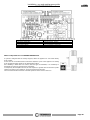
Thermorossi COMPACT S18 EVO Manuale utente
- Categoria
- Termostati
- Tipo
- Manuale utente

COMPACT S18 EVO
ITA - MANUALE DI INSTALLAZIONE, USO E MANUTENZIONE.
FRA - MANUEL D’INSTALLATION, D’UTILISATION ET ENTRETIEN.
ENG - INSTALLATION, USE AND MAINTENANCE GUIDE.
DEU - INSTALLATIONS-, BETRIEBS- UND WARTUNGSANLEITUNG.
ESP - MANUAL DE INSTALACIÓN USO Y MANTENIMIENTO.
ITA – Informazioni importanti per la sicurezza ed il corretto funzionamento.
FRA - A lire impérativement! Informations importantes pour la sécurité et le bon fonctionnement.
ENG - Must read! Important information for safety and correct operation.
DEU - Unbedingt lesen! Wichtige informationen zur sicherheit und zum sicheren betrieb.
ESP - ¡Leer! Informaciones importantes para la seguridad y el correcto funcionamiento.

Installation, use and maintenance guide
COMPACT S18 EVO
Page 1
ENG

Installation, use and maintenance guide
COMPACT S18 EVO
Page 2
ENG
INDEX
1 – INTRODUCTION.................................................................................................................................. 4
2 – TECHNICAL CHARACTERISTICS...................................................................................................... 6
3 – GENERAL DESCRIPTION .................................................................................................................. 7
4 – INSTALLATION ................................................................................................................................... 9
5 – HYDRAULIC CONNECTION ..............................................................................................................12
6 – USE OF THE APPLIANCE .................................................................................................................19
7 ADDITIONAL ROOM TEMPERATURE THERMOSTAT / ADDITIONAL CHRONOTHERMOSTAT ......33
8 - CLEANING AND MAINTENANCE ......................................................................................................35
9 – SMOKE DISCHARGE TUBE AND VENTILATION OF THE ROOMS .................................................39
10 – ALARMS...........................................................................................................................................42
11 - ELECTRICAL WIRING ......................................................................................................................43
12 – INFORMATION FOR THE SKILLED TECHNICIAN .........................................................................44
13 - SPARE PARTS .................................................................................................................................47

Installation, use and maintenance guide
COMPACT S18 EVO
Page 3
ENG
EU Declaration of Conformity (DoC) / Dichiarazione di Conformità UE (DoC)
Company name:
Azienda:
THERMOROSSI S.P.A.
Postal address:
Indirizzo:
VIA GRUMOLO, N° 4
Postcode and city:
Codice postale e città:
36011 ARSIERO (VI)
Telephone number:
Numero di telefono:
0445/741310
E-mail address:
Indirizzo e-mail:
declare that the DoC is issued under our sole responsibility and belongs to the following product:
dichiara che la dichiarazione viene rilasciata sotto la propria responsabilità e si riferisce al seguente prodotto:
Apparatus model / Product:
Descrizione prodotto:
Caldaia a pellet
Pellet boiler
Trademark:
Marchio:
THERMOROSSI
Models:
Modelli:
COMPACT S18 EVO
The object of the declaration described above is in conformity with the relevant Union harmonisation legislation:
L'oggetto della dichiarazione di cui sopra è conforme alla pertinente normativa di armonizzazione dell'Unione:
Direttiva 2014/30/UE, EMCD
Direttiva 2014/35/UE, LVD
Direttiva 2011/65/UE, RoHS
2014/30/EU Directive, EMCD
2014/35/EU Directive, LVD
2011/65/EU Directive, RoHS
Following harmonising standards and/or technical specifications apply:
The following harmonised standards and/or technical specifications have been applied:
EN 55014-1
EN 55014-2
EN 61000-3-2
EN 61000-3-3
EN 60335-1
EN 60335-2-102
EN 62233
EN 50581
EN 303-5 tests carried out by the notified laboratory Kiwa Cermet Italia S.p.a (N.B. 0476) Viale Venezia, 45 31020 San
Vendemiano (TV).
Arsiero, 22/02/2021
Firma/Sign.
IT – SCHEDA PRODOTTO (UE 2015/1187)
EN – PRODUCT FICHE (EU 2015/1187)
FR – FICHE PRODUIT (UE 2015/1187)
NL – PRODUCTGEGEVENSBLAD (EU 2015/1187)
DE – PRODUKTDATENBLATT (EU 2015/1187)
ES – FICHA DE PRODUCTO (UE 2015/1187)
IT – MARCHIO
EN – BRAND
FR – MARQUE
NL – MERK
DE – MARKE
ES – MARCA
THERMOROSSI S.P.A.
IT – MODELLO
EN – MODEL
FR – MODÈLE
NL – MODEL
DE – MODELL
ES – MODELO
COMPACT S18 EVO
IT – CLASSE DI EFFICIENZA ENERGETICA
EN – ENERGY EFFICIENCY CLASS
FR – CLASSE D'EFFICACITE ENERGETIQUE
NL – ENERGIE EFFICIENTIEKLASSE
DE – ENERGIEEFFIZIENZKLASSE
ES – CLASE DE EFICIENCIA ENERGETICA
A +
IT – POTENZA TERMICA NOMINALE
EN – RATED HEAT OUTPUT
FR – PUISSANCE THERMIQUE NOMINALE
NL – NOMINALE WARMTEAFGIFTE
DE – NENNWÄRMELEISTUNG
ES – POTENCIA CALORÍFICA NOMINAL
17 kW
IT – INDICE DI EFFICIENZA ENERGETICA
EN – ENERGY EFFICIENCY INDEX
FR – INDICE D'EFFICACITÉ ÉNERGÉTIQUE
NL – ENERGIE-EFFICIËNTIE-INDEX
DE – ENERGIEEFFIZIENZINDEX
ES – INDICE DE EFICIENCIA ENERGÉTICA
114
IT – EFFICIENZA ENERGETICA STAGIONALE DI RISCALDAMENTO DI AMBIENTE
EN – SEASONAL SPACE HEATING ENERGY EFFICIENCY
FR – EFFICACITÉ ÉNERGÉTIQUE SAISONNIÈRE POUR LE CHAUFFAGE DES LOCAUX
NL – SEIZOENSGEBONDEN ENERGIE-EFFICIËNTIE VOOR RUIMTEVERWARMING
DE – RAUMHEIZUNGS-JAHRESNUTZUNGSGRAD
ES – EFICIENCIA ENERGÉTICA ESTACIONAL DE CALEFACCIÓN DE ESPACIOS
79%
IT – RISPETTARE TUTTE LE ISTRUZIONI RIPORTATE SUL MANUALE DI INSTALLAZIONE USO E MANUTENZIONE
EN – ALWAYS FOLLOW THE INSTRUCTIONS PROVIDED IN THE OPERATING AND MAINTENANCE MANUAL
FR – RESPECTER TOUTES LES INSTRUCTIONS CITÉES DANS LA NOTICE D’INSTALLATION, UTILISATION ET ENTRETIEN
NL – VOLG ALTIJD DE INSTRUCTIES VAN DE INSTALLATIE-, GERUIKERSHANDLEIDING EN DE ONDERHOUDSVOORSCHRIFTEN
DE – ERFÜLLEN DIE ANWEISUNGEN DER INSTALLATION, NUTZUNG UND WARTUNG, DIE IN DER ANLEITUNGSBUCH SIND
ES – RESPECTAR LAS INSTRUCCIONES REPORTADAS EN EL MANUAL DE UTILIZACIÓN Y MANTENIMIENTO

Installation, use and maintenance guide
COMPACT S18 EVO
Page 4
ENG
1 – INTRODUCTION
1.1 SAFETY GUIDELINES
This installation, use and maintenance manual is an integral and essential part of the product and must be kept by the user. Before
commencing with the installation, use and maintenance of the product, carefully read this guide. All local, national and European
regulations regarding the installation and use of the appliance must be met. The Manufacturer recommends carrying out all the
maintenance operations described in this manual.
This appliance must only be used as intended by the manufacturer. Any other use is considered incorrect and therefore hazardous;
consequently, the user shall be totally liable for the product if used improperly. Installation, maintenance and repairs must be carried
out by professionally qualified personnel, certified according to Decree no. 37 of 22 January 2008 and in compliance with current
regulations. In case of repairs only original spare parts supplied by the manufacturer must be used. Incorrect installation or poor
maintenance can injure or damage people, animals or things; in this case the manufacturer shall be relieved of all responsibility.
Before beginning any cleaning or maintenance operation switch off the appliance by means of the 0/I main switch and disconnect
the plug from the electrical power socket. The product must be installed in locations suitable for fire-fighting and furnished with all
the services (power and outlets) which the appliance requires for a correct and safe operation. Any repairs or actions carried out on
any systems, components or internal parts of the appliance, or on any of the accessories supplied with it, that are not specifically
authorised by Thermorossi S.p.A, will automatically void the warranty and the manufacturer's responsibility, pursuant to Italian
Decree no. 224 of the President of the Republic of 24/05/1988, art. 6/b.
It is recommended to keep this manual in a safe place that is easily accessible to all users; if the manual is lost or deteriorated
contact the manufacturer for a replacement copy. If the appliance is sold or transferred to another user ensure that the manual is
handed over with it. The images and figures featured in this manual are purely illustrative and may differ from the actual product.
Furthermore, Thermorossi reserves the right to apply changes to the content of this manual anytime and without notice.
Thermorossi S.p.A. retains copyright on this manual. These instructions may not be reproduced or communicated to third parties or
used in any other way without the necessary authorisation.
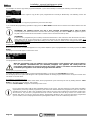
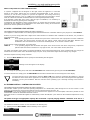
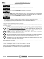
1.2 SAFETY STANDARDS
PERSONAL INJURY
This safety symbol identifies important messages throughout the manual. Read the information marked by this symbol
carefully as non-observance of this message can cause serious injury to persons using the appliance.
DAMAGE TO PROPERTY
This safety symbol identifies messages or instructions that are fundamental for the generator to function well. To avoid
serious damage to the appliance adhere strictly to these instructions.
INFORMATION
This symbol indicates important instructions for good functioning of the generator. If this information is not correctly
observed, the performance of the appliance will not be satisfactory.
1.3 RECOMMENDATIONS
Before using the appliance, carefully read every section of this installation, use and maintenance guide as knowledge
of the information and the regulations contained in it are essential for a correct use of the appliance.
The entire operation concerning the connection of the electric panel must be carried out by expert personnel; no
responsibility will be accepted for damages, even to third parties, if the instructions for installation, use and
maintenance of the appliance are not followed scrupulously. Modifications made to the appliance by the user or on
his behalf, must be considered to be under his complete responsibility. The user is responsible for all the operations
required for the maintenance of the appliance before and during its use.
1.4 GENERAL GUIDELINES
Attention: the appliance must be connected to a system provided with a PE conductor (in compliance with the
specifications concerning low voltage equipment). Before installing the appliance check the efficiency of the earth
circuit of the power supply system.
Attention: the power supply line must have a section which is suitable for the power of the equipment. The cable section must in any
case be no less than 1.5 mm². The appliance requires powering with a voltage of 230V and 50 Hz. Voltage variations greater than
10% of the nominal value can cause irregular operation or damage the electrical device. Position the appliance so that the electric
power outlet in the room is easily accessible. Ensure that a suitable differential switch is installed upstream from the equipment.
Position the power supply cable in order to prevent any contact of the latter with the smoke exhaust pipe or hot parts of the
appliance. If the power cord is damaged it must be replaced by the manufacturer or by an authorised technical assistance service in
order to avoid risks.
Your appliance has obtained the CE marking and has been made to run for 1 hour to check that it functions correctly.
The product must not be used by children under the age of 8 years, by persons with physical, mental or sensorial impairments, or
by persons who are not familiar with the instructions for use and maintenance of the product (the instructions are found in this
booklet). Children must not play with the appliance.
ATTENTION: before every use make sure that the burner and the ash pan are clean, and check that the firebox door is firmly
closed and air tight.

Installation, use and maintenance guide
COMPACT S18 EVO
Page 5
ENG
ATTENTION: the door must always remain shut tight when the appliance is operating. It is strictly forbidden to open the door while
the appliance is in operation. During operation, the smoke exhaust pipes, door, handles and some parts of the appliance may reach
extremely high temperatures: be careful not to touch them and also educate children to be aware of said risks. Do not expose your
body to hot air for long, do not overheat the room in which the appliance is installed, as these actions could cause health problems.
Do not expose plants or animals directly to the hot air flow as this could have noxious effects on them. It is strictly prohibited to use
any type of fuel (liquid, solid...) to light up the appliance: lighting must occur automatically as intended and described in this
installation, use and maintenance booklet; consequently, it is also strictly forbidden to feed pellets (or any other material) into the
brazier. Do not place non-heat resistant or inflammable or combustible objects in the vicinity of the appliance: keep them at a
suitable distance. Do not place wet clothing to dry on the appliance. When using a clothes horse, keep at a suitable distance. It is
strictly prohibited to disconnect the appliance from the electrical power mains while it is in operation.
Caution: do not wet the appliance and do not touch the electrical parts with wet hands. Never vacuum hot ash: this
could damage the vacuum device. All the cleaning operations described in this manual must be carried out when the
appliance is cold and shut off.
Attention! Warning for Swiss users
Refer to the local cantonal regulations imposed by the Fire Department (Mandatory signalling and safety distances)
and the Note concerning installation of heaters issued by the Association of Cantonal Fire Agencies (VKF - AEAI).
ATTENTION: it is mandatory to earth the appliance. If this instruction is not observed serious damage, which is not
covered by warranty, will result to the body of the appliance. Have an electrician check the earthing. There must be
no electric potential (Volt) between the earth of the generator and the actual earth of the systerm.
1.5 TRANSPORTATION AND STORAGE
TRANSPORTATION AND HANDLING
The appliance body must always be in a vertical position when handled and exclusively by means of trolleys. Take special care to
protect the electric panel and all the fragile parts from mechanical impact which could damage them and their correct functioning.
STORAGE
The appliance must be stored in a humid-free environment and sheltered from the weather; avoid placing the appliance directly on
the ground. The Company denies all responsibility for damage caused to wood floors or floors made from any other material.
It is inadvisable to store the product for long periods of time.
1.6 GUIDELINES FOR CORRECT DISPOSAL OF THE PRODUCT
At the end of the product’s useful life it must be disposed of in compliance with applicable regulations and in respect
of the environment, not with urban waste. The product must be consigned to designated sorted waste collection
centres for the disposal of electronic waste authorised by the local municipal councils. Correct disposal not only helps
safeguard the environment but it also promotes recovery and recycling of the materials.

Installation, use and maintenance guide
COMPACT S18 EVO
Page 6
ENG
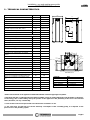
A
DETTAGLIO A
251
274
319
229
253319
334
71 16080
145
136
O100
O60
3/4" F
Mandata
1/2"
Valvola sic
3/4" F
Ritorno
3/4"
Carico scarico
545 756
1380
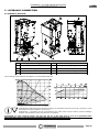
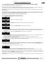
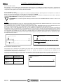
2 – TECHNICAL CHARACTERISTICS
* All the data are based on the appliance fuelled with EN14961-2 standard type-approved pellets.
** Important: take into consideration the fact that the heatable volume is greatly influenced by the insulation of the house,
i.e. the energy class of the building and by the position of the appliance in the planimetry of the house. The indicated
values, therefore, can vary considerably.
*** Test carried out at reduced power with sound level meter at a distance of 3m.
**** The value does not take into account the electricity consumption of the circulating pump, as it depends on the
pressure loss in the plumbing system.
COMPACT S18 EVO
M.U.
VALUES
Height
mm
1,380
Depth
mm
756
Width
mm
545
Empty weight
Kg
200
Firebox power Min. / Max. *
kW
5.29 / 18.28
Thermal output to water Min / Max *
kW
4.66 / 17.06
Min. / Max. * consumption
kg/h
1.14 / 3.94
Run time at reduced /rated power *
h
39 / 11
Boiler class
5
Ø smoke exhaust pipe
mm
100
Min. draught at rated power
Pa - mbar
10 – 0.10
Min. draught at reduced power
Pa - mbar
10 – 0.10
Tank capacity *
kg
45
Water content
l
31
Minimum working pressure
bar - Pa
1.0 – 100,000
Maximum operating pressure
bar - Pa
2.5 – 250,000
Average smoke temperature at rated power *
°C
86
Average smoke temperature at reduced
power *
°C
49
Max delivery water temperature
°C
80
Min water return temperature
°C
55
Smoke flow at rated power *
g/sec
10.2
Smoke flow at reduced power *
g/sec
4.6
Efficiency at rated power *
%
93.31
Efficiency at reduced power *
%
87.98
CO at rated power with 10% O2 *
mg/m³
38
CO at reduced power with 10% O2*
mg/m³
432
Power supply voltage and frequency
V – Hz
230 - 50
Electrical consumption at Rated power ****
W
55
Electrical consumption at Reduced power
****
W
40
Electrical consumption in standby
W
4
Loss of load - water side at 10K
mbar
128
Loss of load - water side at 20K
mbar
32
Heatable volume **
m³
460
Noise level ***
db
38
Legenda
Key
DETTAGLIO A
DETAIL A
3/4" carico scarico
3/4" inlet - outlet
3/4" F ritorno
3/4" F return
3/4" F mandata
3/4" F delivery
1/2" valvola sic.
1/2" safety valve
A
DETTAGLIO A
251
274
319
229
253319
334
71 16080
145
136
O100
O60
3/4" F
Mandata
1/2"
Valvola sic
3/4" F
Ritorno
3/4"
Carico scarico
545 756
1380
A
DETTAGLIO A
251
274
319
229
253319
334
71 16080
145
136
O100
O60
3/4" F
Mandata
1/2"
Valvola sic
3/4" F
Ritorno
3/4"
Carico scarico
545 756
1380

Installation, use and maintenance guide
COMPACT S18 EVO
Page 7
ENG
3 – GENERAL DESCRIPTION
3.1 OPERATING TECHNOLOGY
Your appliance has been built to fully satisfy all your heating and practical requirements. Top-grade components and functions
managed with microprocessor technology guarantee high reliability and optimal performance.
3.2 THE PELLET
The appliance is fuelled by pellets, that is, cylinders of compressed sawdust; it his allows you to fully enjoy the heat of the flame
without having to manually stoke the combustion.
The pellets have a 6 mm diameter and a length between 10 e 20 mm. They have a max moisture content of 8%; a thermal value of
4000/4500 Kcal/kg and density of 630-640 kg/m³. It must be approved according to UNI EN 14961-2 A1 A2.
It is strictly forbidden to use any pellet type other than that specified above. The use of fuel that does not comply with the
above specifications not only immediately invalidates the warranty for the appliance but can also create dangerous
situations. Do not use the appliance as an incinerator, at the risk of voiding the warranty.
3.3 PELLET REFUELLING
The feedbox is situated in the top part of the appliance. The load capacity
specified in the technical data can vary according to the specific weight of the
pellets.
Take special care when loading the tank as the screw feeder at its base is in
motion. Take care when topping up with fuel as the loading area can get very
hot.
ATTENTION: it is normal to find some pellets remaining in the tank even if the
stove shuts off because the pellets have run out.
Attention: when filling up the tank, take care not to drop any pellets into the
internal parts of the appliance, as, in extreme cases, this could generate live
flames.
The manufacturer recommends emptying the tank and vacuuming the screw
feeder zone once a month and during the summer period.
Only pellets complying with the above specifications are to be loaded into the tank; in no case whatsoever must foreign
substances or objects be introduced into the tank, the brazier or any part of the generator.

Installation, use and maintenance guide
COMPACT S18 EVO
Page 8
ENG
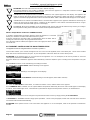
B
C
D
E
I
K
L
M
N
O
P
Q
R
S
U
W
X
Y
Z
AC
AE
V
D
DETTAGLIO D
H
F
AD E
DETTAGLIO E
G
J
T
A
3.4 MAIN COMPONENTS OF THE BOILER
A
Pellet Power Motor
O
Temperature sensor and reset thermostat bulb
B
Circulating pump
P
Automatic relief valve
C
Smoke suction unit
Q
Tube bundle inspection cover
D
Smoke exhaust pipe
R
Control panel
E
Combustion air intake
S
Spiral tube scraper lever
F
Safety pressure switch
T
Power panel
G
Manual reset button
U
Combustion chamber / Patented burner
H
Pellet loading motor
V
Riddling tool
I
Tank pellet
W
Boiler drain/refill tap
J
Main switch 0/I
X
Plant water return
K
Plant water delivery
Y
Safety valve 3 bar
L
Electronic board
AC
2 l expansion tank for boiler protection only
M
Pressure gauge
AD
Smoke thermocouple
N
Lighting heater
AE
Ash pans
Legenda
Key
DETTAGLIO D - E
DETAIL D - E

Installation, use and maintenance guide
COMPACT S18 EVO
Page 9
ENG
A = 200 mm
L = 200 mm
P = 200 mm
4 – INSTALLATION
4.1 APPLIANCE LOCATION
Follow the general guidelines set out in paragraph 1.1 to the letter. Above all keep in mind that the flooring of the
room in which the appliance is being installed must withstand the weight of the stove with the added weight of the
pellet load and the water contained in it.
ATTENTION: The room where the appliance is installed must be well-ventilated and
free from humidity and salty air. A high level of humidity or saltiness in the room can
lead to the onset of rust or corrosion which will not be covered by warranty.
If inflammable materials are located in the vicinity of the appliance (e.g.:
matchboarding, furniture, curtains, pictures and paintings, sofas) it is mandatory to
comply with the minimum distances illustrated (see figure on the side).
Installation in the vicinity of heat-sensitive materials is only permitted if suitable
insulating and fireproof protection is placed between the object and the appliance
(ref. Uni 10683). If the flooring is made of wood or any other combustible material, it
is mandatory to install a fireproof floor protector plate between the appliance and the
floor. Installation in the vicinity of heat-sensitive materials is only permitted if suitable
insulating and fireproof protection is placed between the object and the appliance
(ref. Uni 10683). Failure to observe this instruction will immediately invalidate the
warranty.
The installer must issue a certificate of conformity for the installation which includes the design plans and the
following documents:
a) Report containing the type of materials utilised.
b) Project as defined in Article 5 of Ministerial Decree n° 37 22 January 2008.
d) References to existing partial or previous declarations of conformity (e.g. electrical wiring).
e) Copy of the certificate of recognition of the professional technical qualifications.
These documents must, by law, be kept together with the use and maintenance booklet. The customer is responsible
for verifying, directly or indirectly, that the installation has been carried out to perfection in accordance with relevant
regulations in force. Do not install the appliance in unsuitable rooms such as bedrooms, bathrooms, garages and/or
lock-ups. It is forbidden to place the appliance in environments with an explosive atmosphere.
ATTENTION, the appliance is not simply a household appliance: if the instructions set out in this booklet are not
followed and/or if installation of the appliance is not executed perfectly and/or the provisions in force are not strictly
complied with, dangerous conditions could arise for both objects and persons. It is the user’s responsibility to verify
the presence, in the room, of a vent necessary for supplying oxygen to the generator.
The installer must provide the final user with verbal instructions on the correct use of the appliance when the
appliance is set at work for the first time.

Installation, use and maintenance guide
COMPACT S18 EVO
Page 10
ENG
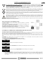
B
A
CC
C
B
A
CC
C
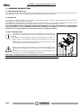
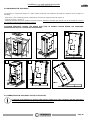
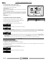
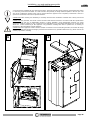
4.2 UNPACKING THE APPLIANCE
The appliance is supplied packaged on a pallet; before positioning and installing it dismantle the appliance from the pallet as
described.
- Remove the cover and the side panels of the pallet (A) and also the edge protectors (B) (Figure 1).
- Undo the 4 screws C (Figure 2).
- Slightly lift the boiler and insert a suitable sack truck (Figure 3): during this operation take special care not to damage the casing or
the protruding parts of the boiler indicated in Figure 4.
- Proceed to position the appliance (see Figure 5-6)
ATTENTION IMPORTANT: HANDLE THE BOILER WITH CARE AS DAMAGE CAUSED DURING THE UNPACKING
OPERATION WILL NOT BE COVERED BY THE WARRANTY.
4.3 CONNECTING THE APPLIANCE TO THE FLUE OUTLET
Connection of the appliance to the flue outlet must be carried out in strict compliance with the instructions
contained in this booklet and particularly with those in Chapter 9.
1
2
3
4
5
6

Installation, use and maintenance guide
COMPACT S18 EVO
Page 11
ENG
B
DETTAGLIO B
Il prese nte disegno è di propriet à esclusiva di THERMOROS SI S.p.A.. La riproduzione totale e/o parziale e la divulgazione a te rzi, senza nostro esplicito consenso sc ritto, verrà perseguito secondo i t ermini di leg ge in vigore.
15/01/2016
Scala
Locazione f ile
Data
Firma
FoglioNote
Materiale
Prodotto
Sviluppo
34/35
TEL. 0445-741310 - FAX 0445-741657
Via Grumolo, 4 - 36011 ARSIER O (Vicenza) - ITALY
S.p.A.
Spessore
Approv. Data approv.
Formato
LIBRETTO USO E MANUTENZIONE RIV MOOD
Cod.
Disegnatore
Volume
Peso
Colore
Revisione
0.000 kg 0.00 mm^3
\\tr-dc01\DatiOffice\Reparti\Tecnico\DWG\Solid_edge\4001\70021924.asm!IMBALLATA
Descrizione
Revisione Autore Data
Descrizione
LAMIERA
Il fornitore è responsa bile della corretta realizzazione del
particolare c ome indicano l e viste di p rogetto; lo s viluppo
piano deve esse re verifica to ed eve ntualme nte modifi cato dal
fornitore in funzione delle macchine di piegatura c he
andranno a reali zzare il partic olare.
STA MPI E FUSI ONI
É obbl igo da p arte del fornitore, prima di
realizza re qualsiasi attrezzatu ra, fornire a
THER MOROSSI S.p.A. i fi le
tridimensional i dei partic olari definitivi
X
Figura 1
FLANGIA
PRE-TAGLIATA
600 mm
4.4 HANDLE
Your appliance is supplied with a riddling tool for opening and closing the firebox door (Figure 1) to facilitate cleaning (see the
dedicated paragraph). When not in use, it can be stowed on the rear of the appliance as indicated in Figure 2.
4.5 DRAWING COMBUSTION AIR FROM OUTSIDE
The appliance is fitted with an intake to enable drawing in the combustion air directly from
outside the building. Connect the air intake on the appliance to the exterior of the building
with suitable piping, capable of resisting high temperatures. The pipe’s length must be
maximum 600 mm.
ATTENTION: The suction duct must be protected with a grid and never be
clogged. The protection grid, if installed, must be inspected and cleaned on a
monthly basis. Moreover, a suitable windbreak fitting must be installed in the
duct’s terminal.
1
2
DETAIL B

Installation, use and maintenance guide
COMPACT S18 EVO
Page 12
ENG
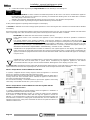
1
3
2
4
56
W
X
K
Y
Z
5 – HYDRAULIC CONNECTION
5.1 HYDRAULIC DIAGRAM
The circulating pump installed in the appliance has the following features:
ATTENTION: flexible tubing with a minimum length of 70 centimetres must be used for all connections, as this
will facilitate moving the appliance for servicing.
ATTENTION: a connection must be made between the safety valve and the outlet to prevent damaging
materials surrounding the boiler when the valve is activated.
ATTENTION: To avoid continual startups and shut offs, the size of the plant must be such as to guarantee power
absorption that is not less than the power generated by the boiler running at reduced power.
1
System circulating pump
6
2 l closed expansion tank
2
Automatic relief valve
W
System drain/refill gate valve
3
Boiler water temperature sensor
X
Plant return
4
Reset thermostat bulb
K
Plant delivery
5
Pressure gauge 0 - 4 bar
Y
Safety valve 3 bar

Installation, use and maintenance guide
COMPACT S18 EVO
Page 13
ENG
5.2 GUIDELINES FOR PLANTS WITH ZONE VALVES
Legenda
Key
Elettrovalvola sempre aperta
(zona con più assorbimento)
Solenoid valve always open
(zone with the most absorption)
COLLETTORE ANDATA
DELIVERY HEADER
COLLETTORE RITORNO
RETURN HEADER
A: andata impianto riscaldamento
A: heating system delivery
R: ritorno impianto riscaldamento
R: heating system return
S: saracinesca
S: gate valve
TA: elettrovalvola
TA: solenoid valve
VNR: valvola di non ritorno
VNR: nonreturn valve
VEC: vaso di espansione chiuso per protezione impianto
VEC: closed expansion tank for system protection
VM3VT: valvola miscelatrice termostatca 55°C
VM3VT: thermostatic mixing valve 55°C
APPARECCHIO
APPLIANCE
Over 61°C, the generator circulating pump is always active as the heat must be dispersed; consequently, the solenoid valve in the
zone with the greatest absorption must be opened for the following reasons:
• to prevent the generator from continually starting up and shutting off caused by the inevitable loss of heat to the header and/or due
to system tubing.
• to prevent the generator from raising the water temperature by just a few degrees each time it is switched off then back on until it
shuts down due to exceeding the maximum threshold temperature.
To adjust the ambient temperature in which the valve opened, we recommend connecting the room temperature thermostat to the
MODEM terminal that allows the machine to be shut off via an external contact and therefore also restarted.
This ensures that the generator only activates if there is a real request for heat from the zone in which the chronothermostat is
installed.
Several parallel-connected room temperature thermostats can be installed in the MODEM terminal. This will ensure that the zone
requesting heat automatically activates the generator.
In the event of frequent startups and shut offs due to the heat produced by the generator not being absorbed, the manual reset
safety thermostat trips and blocks the generator.
N.B. Use chronothermostats having at least 2°C hysterisis.
The system must always be capable of absorbing all the power that the generator is capable of delivering. If you do not observe this
requirement , the generator could be subjected to numerous stops and starts. It is recommended not to exceed three lighting cycles
per day.
VEC
TATA
Elettrova lvola sem p re ap erta
(zon a c on p iu' assorb im en to)
COLLETTORE ANDATA
COLLETTORE RITORNO
TA
S
S
VM3VT
A
R
A : andata impianto riscaldamento
R : ritorno impianto riscaldamento
S : saracinesca
VNR : valvola di non ritorno
VEC : vaso di espansione chiuso per protezione impianto
VM3VT : valvola miscelatrice termostatica 55°c.
TA : elettrovalvola
VNR
APPARECCHIO
schema idraulico - valvole di zona.dft 03/05/2016

Installation, use and maintenance guide
COMPACT S18 EVO
Page 14
ENG
5.3 HYDRAULIC DIAGRAM WITH HEATING ONLY
Legenda
Key
A: andata impianto riscaldamento
A: heating system delivery
R: ritorno impianto riscaldamento
R: heating system return
S: saracinesca
S: gate valve
VNR: valvola di non ritorno
VNR: nonreturn valve
VEC: vaso di espansione chiuso per protezione impianto
VEC: closed expansion tank for system protection
VM3VT: valvola miscelatrice punto fisso 55°C
VM3VT: mixing valve, fixed point 55°C
VSP: valvola saracinesca (da parzializzare in funzione
delle perdite di carico dell'impianto)
VSP: gate valve (throttle according to pressure drop in
the system)
APPARECCHIO
APPLIANCE
ATTENTION: it is mandatory to earth the generator. If this instruction is not observed serious damage, which
is not covered by warranty, will result to the body of the appliance. Have a skilled electrician check the
earthing. There must be no electric potential (Volt) between the generator earth and the system’s real earth
(earth plate). To prevent electrochemical corrosion of the appliance body do not use galvanised pipes and
fittings. Other materials must be earthed with special earthing cables in order to obtain a unipotential
earthing system.
RS
AS
VEC
VM3VT
A : andata impianto riscaldamento
R : ritorno impianto riscaldamento
S : saracinesca
VNR : valvola di non ritorno
VEC : vaso di espansione chiuso per protezione impianto
VM3VT : valvola miscelatrice punto fisso 55°C
VSP: valvola saracinesca (da parzializzare in funzione delle perdite di carico dell'impianto)
VSP
R
A
APPARECCHIO
VNR

Installation, use and maintenance guide
COMPACT S18 EVO
Page 15
ENG
5.4 EXAMPLE OF HYDRAULIC DIAGRAM WITH INTERSPACED BOILER COILS OR BOILER COILS
Legenda
Key
BOLLITORE AD INTERCAPEDINE
AIR-CASED BOILER
A: andata impianto riscaldamento
A: heating system delivery
R: ritorno impianto riscaldamento
R: heating system return
S: saracinesca
S: gate valve
VNR: valvola di non ritorno
VNR: nonreturn valve
VEC: vaso di espansione chiuso per protezione impianto
VEC: closed expansion tank for system protection
VM3VT: valvola miscelatrice termostatica punto fisso 55°C
VM3VT: thermostatic mixing valve, fixed point 55°C
VSP: valvola saracinesca (da parzializzare in funzione delle perdite
di carico dell'impianto)
VSP: gate valve (throttle according to pressure drop in the system)
APPARECCHIO
APPLIANCE
ATTENTION: The water temperature in the boiler tubes in this case is not adjustable and depends on the system's delivery
temperature, that is the temperature set in the generator. The boiler tubes can be installed on the water return circuit. It is
recommended to install a water softener in the domestic water system in order to maintain the boiler at its peak efficiency.
ATTENTION: it is mandatory to earth the generator. If this instruction is not observed serious damage, which
is not covered by warranty, will result to the body of the appliance. Have a skilled electrician check the
earthing. There must be no electric potential (Volt) between the generator earth and the system’s real earth
(earth plate). To prevent electrochemical corrosion of the appliance body do not use galvanised pipes and
fittings. Other materials must be earthed with special earthing cables in order to obtain a unipotential
earthing system.
SVNR
A
VEC
BOLLITORE AD
INTERCAPEDINE
SS
VM3VT
VSP
R
A : andata impianto riscaldamento
R : ritorno impianto riscaldamento
S : saracinesca
VNR : valvola di non ritorno
VEC : vaso di espansione chiuso per protezione impianto
VM3VT : valvola miscelatrice termostatica punto fisso 55°c
VSP: valvola saracinesca (da parzializzare in funzione delle perdite di carico dell'impianto
schema idraulico - bollitore a intercapedine.dft 03/05/2016
APPARECCHIO
R
A

Installation, use and maintenance guide
COMPACT S18 EVO
Page 16
ENG
5.5 EXAMPLE OF HYDRAULIC DRAWING WITH BOILER COILS AND HEATING
Legenda
Key
Sonda PT100
Sensor PT100
Alimentazione dalla scheda alla VDEV3V
Power supply from the board to the VDEV3V
Alla morsettiera CN5 (Morsetti 5 - 6)
To the terminal block CN5 (Terminals 5 - 6)
Alla morsettiera CN3 (Morsetti 5 -7-8)
To the terminal block CN3 (Terminals 5 - 7 - 8)
A: andata impianto riscaldamento
A: heating system delivery
R: ritorno impianto riscaldamento
R: heating system return
S: saracinesca
S: gate valve
VNR: valvola di non ritorno
VNR: nonreturn valve
VEC: vaso di espansione chiuso per protezione
impianto
VEC: closed expansion tank for system protection
VM3VT: valvola miscelatrice term. fisso 55°C
VM3VT: thermostatic mixing valve, fixed point 55°C
VSP: valvola saracinesca (da parzializzare in funzione
delle perdite di carico dell'impianto)
VSP: gate valve (throttle according to pressure drop in
the system)
VDEV3V: valvola deviatrice 3 vie
VDEV3V: three-way diverting valve
APPARECCHIO
APPLIANCE
In order to guarantee correct absorption of the heat produced by the generator it is advisable to use a boiler tube with volume and
heat exchange capacity suitable for the power of the generator. The boiler tube must have a minimum capacity of 300l. In any case
the boiler tube must be capable of absorbing all the power that the generator is capable of delivering. If this rule is not observed, the
generator could raise the water temperature to such a point as to activate the safety limit thermostat which stops the fuel from
dropping into the burner and therefore forces the appliance to shut off.
The installer is required to install a valve that switches over to the system, powered by the appliance’s control unit, which trips when
the boiler tube is thermally “satisfied ”. Consequently, the system must be designed in such a way that the hot water produced by
the generator can reach the various rooms by acting on the zone valves.
ATTENTION: it is mandatory to earth the generator. If this instruction is not observed serious damage, which
is not covered by warranty, will result to the body of the appliance. Have a skilled electrician check the
earthing. There must be no electric potential (Volt) between the generator earth and the system’s real earth
(earth plate). To prevent electrochemical corrosion of the appliance body do not use galvanised pipes and
fittings. Other materials must be earthed with special earthing cables in order to obtain a unipotential
earthing system.
S
RSVNR
S
S
A
VEC
VM3VT
VSP
A : andata impianto riscaldamento
R : ritorno impianto riscaldamento
S : saracinesca
VNR : valvola di non ritorno
VEC : vaso di espansione chiuso per protezione impianto
VSP : valvola saracinesca ( da parzializzare in funzione delle
perdite di carico dell' impianto).
VM3VT : valvola miscelatrice term. fisso 55°c.
VDEV3V : valvola deviatrice 3 vie
Alla m orsettiera CN3
(Morsetti 5 - 7 - 8)
Alla m orsettiera CN5
(Morsetti 5 - 6 )
Alim enta zion e dalla scheda alla VDEV3 V
Sond a PT10 0
schema idraulico - bollitore a serpentino.dft 03/05/2016
APPARECCHIO
R
A
VDEV3V

Installation, use and maintenance guide
COMPACT S18 EVO
Page 17
ENG
5.6 HYDRAULIC DIAGRAM WITH THERMOCELL + THERMOPUFFER + HEATING
Legenda
Key
Attenzione: chiudere tutti i fori non usati del puffer
Note: close all the holes not used by the puffer
Radiatori
Radiators
Riscaldamento pavimento
Underfloor heating
Alla morsettiera CN5 (morsetti 3-4)
To the terminal block CN5 (Terminals 3-4)
Alla morsettiera CN5 (morsetti 1-2)
To the terminal block CN5 (Terminals 1-2)
Sonda 1
Sensor 1
Sonda 2
Sensor 2
Tubi di collegamento accumuli
Connection tubes to puffers
Thermopuffer aggiuntivo
Additional Thermopuffer
Vaso di espansione chiuso
Vaso di espansione chiuso
Thermocell o Thermopuffer
Thermocell or Thermopuffer
APPARECCHIO
APPLIANCE
Valvola miscelatrice 3 vie termostatica 55°C punto fisso
Three-way thermostatic mixing valve 55°C, fixed point
Valvola saracinesca (da parzializzare in funzione delle perdite di
carico dell’impianto)
Gate valve (throttle according to pressure drop in the system)
Circolatore
Circulating pump
Valvola 3 vie
Three-way valve
Saracinesca
Gate valve
Valvola di non ritorno
Nonreturn valve
Termostato sicurezza a protezione dell’impianto a pavimento
Safety thermostat for protection of the under floor heating system
ATTENTION: the preload pressure of the expansion tank must be greater than the plant pressure: for an expansion
tank preloaded to 2 bar the plant must be loaded to a pressure that does not exceed 1.5 bar.
ATTENTION: The Thermocell is only fitted with a connection to 230V - 50Hz power line; the settings of Sensor S1
and Sensor S2 must only be controlled by the appliance. Connect the two sensors PT 100 (optional code no.
60010695) to the terminals on the appliance’s "Sensor S1" and "Sensor S2" board. Sensor S2 must always be
positioned at the same height as the water delivery to the system.
ATTENTION: Sensor S1 must be set at a range of between 60°C and 65°C, sensor S2 must be set at a range of
between 50°C and 55°C. These settings are only approximate as the optimal setting is carried out by the Service
Centre on site during the initial testing of the appliance, following the assessment of the system’s specific
characteristics.
Attenzione : chiudere tutti i fori
non usati del puffer
Sonda 2
Sonda 1
non usati del puffer
Attenzione : chiudere tutti i fori Riscaldamento pavimento
Radiatori
Valvola di non ritorno
Valvola miscelatrice 3 vie termostatica 55°c
Valvola saracinesca (da parzializzare in
funzione delle perdite di carico dell'impianto)
Thermopuffer aggiuntivo
Tubi di collegamento accumuli
Vaso di espansione chiuso
punto fisso.
Valvola a 3 vie
Circolatore
Thermocell o Thermopuffer
Saracinesca
Alla morsettiera CN5
(morsetti 1-2)
Alla morsettiera CN5
(morsetti 3-4)
VM3VT
M
VM3VT
A
APPARECCHIO
R
Termostato sicurezza a protezione dell'impianto a pavimento
schema idraulico - thermocell.dft 03/05/2016
°C
M
°C

Installation, use and maintenance guide
COMPACT S18 EVO
Page 18
ENG
ATTENTION: it is mandatory to earth the generator. If this instruction is not observed serious damage, which
is not covered by warranty, will result to the body of the appliance. Have a skilled electrician check the
earthing. There must be no electric potential (Volt) between the generator earth and the system’s real earth
(earth plate). To prevent electrochemical corrosion of the appliance body do not use galvanised pipes and
fittings. Other materials must be earthed with special earthing cables in order to obtain a unipotential
earthing system.
ATTENTION: Sensor S2 and sensor S1 must be connected to the dedicated clamps on the terminal block as indicated in the
diagram. To view the readings of Sensors S1 and S2 on the display it is necessary to activate the THERMOCONTROL function.
5.7 INSTRUCTIONS FOR EXECUTING THE HYDRAULIC SYSTEM CLOSED EXPANSION TANK
To install the system with a closed expansion tank refer to the requirements laid down in EN 10412-2:2009 for appliances with
nominal heat output not exceeding 35 kW or in the Ministerial Decree Collection R edition 2009 for appliances with nominal heat
output exceeding 35kW.
The hydraulic system must be installed by qualified personnel who are familiar with the standards mentioned above and who have
the appropriate professional requirements to release the declaration of conformance in accordance with Ministerial Decree n° 37 of
22 January 2008.
The generator is already supplied with the following safety devices on board:
a) closed expansion tank for generator protection only*
b) ordinary safety valve 3 bar, not I.S.P.E.S.L. approved
c) an automatic reset temperature limiting device;
This is an automatic adjustment device that interrupts the fuel supply to the generator when the water reaches the
temperature setting. The system starts up again automatically when the water temperature drops below the preset value.
d) a manual reset temperature limiting safety device;
This is an automatic device that interrupts the fuel supply when the water reaches the maximum permissible temperature.
The fuel infeed will only restart when the water temperature drops below a preset value and after the device has been
reset manually.
e) circulation system.
The appliance is fitted with a circulating pump connected to the return pipes which is controlled directly by the
generator’s control board.
* An additional closed expansion tank must be series-connected to the generator as protection for the system.
The nominal volume of the additional closed expansion tank must be sized in relation to the volume of expansion of the water
contained in the system. Thermorossi prescribes that the size of the additional closed expansion tank must be equal to 10% of the
water contained in the system.
The previous chapter does not replace the above standards to which it makes reference. The qualified installer must in
any case be fully aware of the above standards and their amending versions.

Installation, use and maintenance guide
COMPACT S18 EVO
Page 19
ENG
6 – USE OF THE APPLIANCE
The appliance, when operating, could be hot to the touch, particularly the door of the combustion chamber: take care
when handling the appliance components. Your appliance has obtained the CE marking and has been made to run for
at least one hour to check that it functions correctly. The product must not be used by children, by persons with
physical or mental impairments, by persons who are not familiar with the instructions for use and maintenance of the
product (the instructions are found in this use and maintenance booklet).
ATTENTION: before use always check that the burner is clean and that the ash pan is clean.
ATTENTION: the door must always remain shut tight when the appliance is operating. It is strictly forbidden to open the
door while the appliance is in operation. While the appliance is in operation the smoke exhaust pipes can reach
extremely high temperatures: do not touch them! It is strictly prohibited to use any type of fuel (liquid, solid...) other than
pallet to light up the appliance: lighting must occur automatically as intended and described in this installation, use and
maintenance booklet; consequently, it is also strictly forbidden to feed pellets (or any other material) into the brazier. Do
not place non-heat resistant or inflammable or combustible objects in the vicinity of the appliance: keep them at a
suitable distance. Do not place wet clothing to dry on the appliance. When using a clothes horse, keep at a suitable
distance. It is strictly prohibited to disconnect the appliance from the electrical power mains during normal operation.
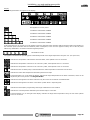
6.1 DESCRIPTION OF THE CONTROL PANEL
The control panel is managed by a microprocessor. The temperature detection system uses thermocouples. The large display
improves the appliance management by making read-outs and functions promptly available. The main feature of the panel is the all-
automatic management of the appliance. The controls and the various displays are described below.
Flame button
Pressing this button when the appliance is off activates the START sequence, sets the operating power in the WORK
mode or shuts off the appliance by activating the OFF sequence.
Degrees Button
Press this button to set the target water temperature; the setting range is between 65 °C and 73 °C. This value is
displayed on the left side of the display next to the thermometer symbol.
Attention: the target temperature is only considered if the appliance is in AUTO mode.
Scroll buttons (only in the Menu)
Press MINUS key to lower the value. Press PLUS key to raise the preset value.
Clock button
Press this button to activate / deactivate the programming.
Menu button
Press this button to access the main menu. You can scroll the setting screens shown below, which will be described
in detail in the following paragraphs. To access the functions of each subwindow wait a few seconds.
DATE/TIME This button is used to set the day of the week, the hour and minutes.
CHRONO This button is used to set the programmed on and off sequences.
LEVEL Is used to change the rotation speed of the smoke suction unit.
THERMOCONTROL Enables you to activate or deactivate the control of a puffer (if installed). This screen only appears if the
two optional sensors are connected to the appliance.
ACS SUMMER Enables you to activate or deactivate the dedicated control of a boiler (if installed) that produces
domestic hot water (ACS), thereby cutting off the system.
This screen only appears if the optional sensor is connected to the appliance.
T.AMBIENT Enables you to control the ON/OFF cycles of the appliance according to the desired room temperature.
This screen only appears if the optional sensor is connected to the appliance.
THERMO ACS Enables you to activate control of a boiler (if installed) for domestic hot water (ACS) assigning absolute
priority to the boiler requirements before replenishing the system. This screen only appears if the
optional sensor is connected to the appliance.
La pagina si sta caricando...
La pagina si sta caricando...
La pagina si sta caricando...
La pagina si sta caricando...
La pagina si sta caricando...
La pagina si sta caricando...
La pagina si sta caricando...
La pagina si sta caricando...
La pagina si sta caricando...
La pagina si sta caricando...
La pagina si sta caricando...
La pagina si sta caricando...
La pagina si sta caricando...
La pagina si sta caricando...
La pagina si sta caricando...
La pagina si sta caricando...
La pagina si sta caricando...
La pagina si sta caricando...
La pagina si sta caricando...
La pagina si sta caricando...
La pagina si sta caricando...
La pagina si sta caricando...
La pagina si sta caricando...
La pagina si sta caricando...
La pagina si sta caricando...
La pagina si sta caricando...
La pagina si sta caricando...
La pagina si sta caricando...
La pagina si sta caricando...
-
 1
1
-
 2
2
-
 3
3
-
 4
4
-
 5
5
-
 6
6
-
 7
7
-
 8
8
-
 9
9
-
 10
10
-
 11
11
-
 12
12
-
 13
13
-
 14
14
-
 15
15
-
 16
16
-
 17
17
-
 18
18
-
 19
19
-
 20
20
-
 21
21
-
 22
22
-
 23
23
-
 24
24
-
 25
25
-
 26
26
-
 27
27
-
 28
28
-
 29
29
-
 30
30
-
 31
31
-
 32
32
-
 33
33
-
 34
34
-
 35
35
-
 36
36
-
 37
37
-
 38
38
-
 39
39
-
 40
40
-
 41
41
-
 42
42
-
 43
43
-
 44
44
-
 45
45
-
 46
46
-
 47
47
-
 48
48
-
 49
49


Thermorossi COMPACT S18 EVO Manuale utente
- Categoria
- Termostati
- Tipo
- Manuale utente
in altre lingue
Documenti correlati
Altri documenti
-
 Kalor 20B Manuale utente
-
 MCZ DUO HYDRO-AIR Guida d'installazione
-
Ravelli HR EVO 14 Hydro Manuale del proprietario
-
-
Piazzetta P957 Instructions For Installation, Use And Maintenance Manual
-
La Nordica CLEO COMBI Bordeaux Manuale del proprietario
-
La Nordica Nicoletta Forno Evo Manuale del proprietario

