
Lexmark
TM
W820 Options
4025-XXX
Lexmark and Lexmark with diamond design are
trademarks of Lexmark International, Inc., registered
in the United States and/or other countries.
• Table of Contents
• Start Diagnostics
• Safety and Notices
• Trademmaarrkkss
•Index

Edition: May 2001
The following paragraph does not apply to any country where such provisions are inconsistent with local law:
LEXMARK INTERNATIONAL, INC. PROVIDES THIS PUBLICATION “AS IS” WITHOUT WARRANTY OF ANY KIND,
EITHER EXPRESS OR IMPLIED, INCLUDING, BUT NOT LIMITED TO, THE IMPLIED WARRANTIES OF
MERCHANTABILITY OR FITNESS FOR A PARTICULAR PURPOSE. Some states do not allow disclaimer of express or
implied warranties in certain transactions; therefore, this statement may not apply to you.
This publication could include technical inaccuracies or typographical errors. Changes are periodically made to the
information herein; these changes will be incorporated in later editions. Improvements or changes in the products or the
programs described may be made at any time.
Comments may be addressed to Lexmark International, Inc., Department D22A/032-2, 740 West New Circle Road,
Lexington, Kentucky 40550, U.S.A or e-mail at ServiceInfoAndT[email protected]. Lexmark may use or distribute any
of the information you supply in any way it believes appropriate without incurring any obligation to you. You can purchase
additional copies of publications related to this product by calling 1-800-553-9727. In other countries, contact your point of
purchase.
Lexmark and Lexmark with diamond design are trademarks of Lexmark International, Inc., registered in the United States
and/or other countries.
PostScript is a registered trademark of Adobe Systems Incorporated.
Other trademarks are the property of their respective owners.
©
Copyright Lexmark International, Inc. 2001.
All rights reserved.
UNITED STATES GOVERNMENT RESTRICTED RIGHTS
This software and documentation are provided with RESTRICTED RIGHTS. Use, duplication or disclosure by the
Government is subject to restrictions as set forth in subparagraph (c)(1)(ii) of the Rights in Technical Data and Computer
Software clause at DFARS 252.227-7013 and in applicable FAR provisions: Lexmark International, Inc., Lexington, KY
U.S.A. P/N 12G3782

Contents iii
4025 Options
Contents
Preface . . . . . . . . . . . . . . . . . . . . . . . . . . . . . . . . . . . . . . . . . . . . . . . . . . . . . . . . . . . . . . . . . . . . . . . . . . ix
Safety Information . . . . . . . . . . . . . . . . . . . . . . . . . . . . . . . . . . . . . . . . . . . . . . . . . . . . . . . . . . . . . . x
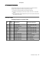
Maintenance Approach . . . . . . . . . . . . . . . . . . . . . . . . . . . . . . . . . . . . . . . . . . . . . 1-1
Tools Required For Service . . . . . . . . . . . . . . . . . . . . . . . . . . . . . . . . . . . . . . . . . . 1-1
Symbols Used in this Manual . . . . . . . . . . . . . . . . . . . . . . . . . . . . . . . . . . . . . . . . 1-1
Safety Details . . . . . . . . . . . . . . . . . . . . . . . . . . . . . . . . . . . . . . . . . . . . . . . . . . . . . 1-1
Printer Power Supply and Electrical Components . . . . . . . . . . . . . . . . . . . . . . . 1-2
Mechanical Components . . . . . . . . . . . . . . . . . . . . . . . . . . . . . . . . . . . . . . . . . . 1-2
Printer Laser Components . . . . . . . . . . . . . . . . . . . . . . . . . . . . . . . . . . . . . . . . 1-2
Printer Fuser Components . . . . . . . . . . . . . . . . . . . . . . . . . . . . . . . . . . . . . . . . 1-3
Safety Components . . . . . . . . . . . . . . . . . . . . . . . . . . . . . . . . . . . . . . . . . . . . . . 1-3
Caution Labels . . . . . . . . . . . . . . . . . . . . . . . . . . . . . . . . . . . . . . . . . . . . . . . . . 1-3
Envelope Feeder . . . . . . . . . . . . . . . . . . . . . . . . . . . . . . . . . . . . . . . . . . . . . . . . . . . 1-4
Envelope Feeder Overview . . . . . . . . . . . . . . . . . . . . . . . . . . . . . . . . . . . . . . . . 1-4
Schematic Diagram of the Envelope Feeder Operation . . . . . . . . . . . . . . . . . . 1-5
Envelope Feeder Power and Control . . . . . . . . . . . . . . . . . . . . . . . . . . . . . . . . 1-6
Envelope Feeder Drive Generation and Distribution . . . . . . . . . . . . . . . . . . . . . 1-6
Envelope Feeder Power . . . . . . . . . . . . . . . . . . . . . . . . . . . . . . . . . . . . . . . . . . 1-6
Envelope Feeder Control . . . . . . . . . . . . . . . . . . . . . . . . . . . . . . . . . . . . . . . . . 1-7
Envelope Feeder Control Components . . . . . . . . . . . . . . . . . . . . . . . . . . . . . . . 1-8
Mechanical Drive . . . . . . . . . . . . . . . . . . . . . . . . . . . . . . . . . . . . . . . . . . . . . . . . 1-8
Envelope Feeder Paper Path . . . . . . . . . . . . . . . . . . . . . . . . . . . . . . . . . . . . . 1-10
Envelope Feeder Paper Path Components . . . . . . . . . . . . . . . . . . . . . . . . . . . 1-10
Envelope Feeder General Specifications . . . . . . . . . . . . . . . . . . . . . . . . . . . . 1-11
Duplex . . . . . . . . . . . . . . . . . . . . . . . . . . . . . . . . . . . . . . . . . . . . . . . . . . . . . . . . . . 1-12
Duplex Overview . . . . . . . . . . . . . . . . . . . . . . . . . . . . . . . . . . . . . . . . . . . . . . . 1-12
Schematic Diagram of the Duplex Operation . . . . . . . . . . . . . . . . . . . . . . . . . 1-13
Duplex Power and Control . . . . . . . . . . . . . . . . . . . . . . . . . . . . . . . . . . . . . . . . 1-13
Duplex Drive Generation and Distribution . . . . . . . . . . . . . . . . . . . . . . . . . . . . 1-13
Duplex Power . . . . . . . . . . . . . . . . . . . . . . . . . . . . . . . . . . . . . . . . . . . . . . . . . 1-14
Duplex Control . . . . . . . . . . . . . . . . . . . . . . . . . . . . . . . . . . . . . . . . . . . . . . . . 1-14
Duplex Control Components . . . . . . . . . . . . . . . . . . . . . . . . . . . . . . . . . . . . . . 1-15
Mechanical Drive . . . . . . . . . . . . . . . . . . . . . . . . . . . . . . . . . . . . . . . . . . . . . . . 1-15
Duplex Drive Components . . . . . . . . . . . . . . . . . . . . . . . . . . . . . . . . . . . . . . . 1-16
Duplex Paper Path . . . . . . . . . . . . . . . . . . . . . . . . . . . . . . . . . . . . . . . . . . . . . 1-17
Duplex Paper Path Components . . . . . . . . . . . . . . . . . . . . . . . . . . . . . . . . . . . 1-20
General Information. . . . . . . . . . . . . . . . . . . . . . . . . . . . . . . . . . . . . . . . . . . . . . . . . . . . . . . . . . . 1-1

iv Contents
4025 Options
Duplex General Specifications . . . . . . . . . . . . . . . . . . . . . . . . . . . . . . . . . . . . . 1-21
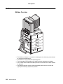
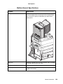
Mailbox . . . . . . . . . . . . . . . . . . . . . . . . . . . . . . . . . . . . . . . . . . . . . . . . . . . . . . . . . . 1-22
Mailbox Overview . . . . . . . . . . . . . . . . . . . . . . . . . . . . . . . . . . . . . . . . . . . . . . 1-22
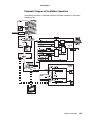
Schematic Diagram of the Mailbox Operation . . . . . . . . . . . . . . . . . . . . . . . . . 1-23
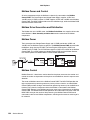
Mailbox Power and Control . . . . . . . . . . . . . . . . . . . . . . . . . . . . . . . . . . . . . . . 1-24
Mailbox Drive Generation and Distribution . . . . . . . . . . . . . . . . . . . . . . . . . . . 1-24
Mailbox Power . . . . . . . . . . . . . . . . . . . . . . . . . . . . . . . . . . . . . . . . . . . . . . . . . 1-24
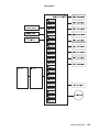
Mailbox Control . . . . . . . . . . . . . . . . . . . . . . . . . . . . . . . . . . . . . . . . . . . . . . . . 1-24
Mailbox Control Components . . . . . . . . . . . . . . . . . . . . . . . . . . . . . . . . . . . . . 1-26
Mechanical Drive . . . . . . . . . . . . . . . . . . . . . . . . . . . . . . . . . . . . . . . . . . . . . . . 1-27
Drive for the Mailbox . . . . . . . . . . . . . . . . . . . . . . . . . . . . . . . . . . . . . . . . . . . . 1-28
Mailbox Mechanical Drive Components . . . . . . . . . . . . . . . . . . . . . . . . . . . . . 1-29
Mailbox Paper Path . . . . . . . . . . . . . . . . . . . . . . . . . . . . . . . . . . . . . . . . . . . . . 1-30
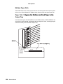
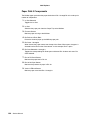
Paper Path 1: Bypass the Mailbox and Feed Paper to the Output Tray . . . . . . 1-30
Paper Path 1 Components . . . . . . . . . . . . . . . . . . . . . . . . . . . . . . . . . . . . . . . . 1-31
Paper Path 2: Feed Paper to Bin 10 . . . . . . . . . . . . . . . . . . . . . . . . . . . . . . . . 1-32
Paper Path 2 Components . . . . . . . . . . . . . . . . . . . . . . . . . . . . . . . . . . . . . . . . 1-33
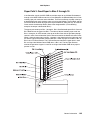
Paper Path 3: Feed Paper to Bins 2 through 10 . . . . . . . . . . . . . . . . . . . . . . . 1-35
Paper Path 3 Components . . . . . . . . . . . . . . . . . . . . . . . . . . . . . . . . . . . . . . . . 1-36
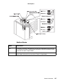
Mailbox Modes . . . . . . . . . . . . . . . . . . . . . . . . . . . . . . . . . . . . . . . . . . . . . . . . . 1-37
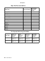
Paper Size Recommendations . . . . . . . . . . . . . . . . . . . . . . . . . . . . . . . . . . . . 1-38
Print Speeds While Using the Mailbox . . . . . . . . . . . . . . . . . . . . . . . . . . . . . . 1-38
Mailbox General Specifications . . . . . . . . . . . . . . . . . . . . . . . . . . . . . . . . . . . . 1-39
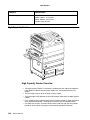
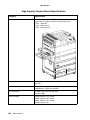
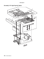
High Capacity Feeder . . . . . . . . . . . . . . . . . . . . . . . . . . . . . . . . . . . . . . . . . . . . . . 1-40
High Capacity Feeder Overview . . . . . . . . . . . . . . . . . . . . . . . . . . . . . . . . . . . 1-40
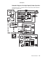
Schematic Diagram of the High Capacity Feeder Operation . . . . . . . . . . . . . . 1-41
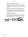
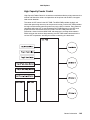
High Capacity Feeder Power and Control . . . . . . . . . . . . . . . . . . . . . . . . . . . . 1-42
High Capacity Feeder Drive Generation and Distribution . . . . . . . . . . . . . . . . 1-42
High Capacity Feeder Power . . . . . . . . . . . . . . . . . . . . . . . . . . . . . . . . . . . . . . 1-42
High Capacity Feeder Control . . . . . . . . . . . . . . . . . . . . . . . . . . . . . . . . . . . . . 1-43
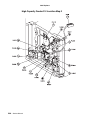
High Capacity Feeder Control Components . . . . . . . . . . . . . . . . . . . . . . . . . . 1-44
Mechanical Drive . . . . . . . . . . . . . . . . . . . . . . . . . . . . . . . . . . . . . . . . . . . . . . . 1-45
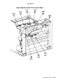
Drive for High Capacity Feeder . . . . . . . . . . . . . . . . . . . . . . . . . . . . . . . . . . . . 1-45
Drive for Tray 3 . . . . . . . . . . . . . . . . . . . . . . . . . . . . . . . . . . . . . . . . . . . . . . . . . 1-46
Mechanical Drive Tray 3 Components . . . . . . . . . . . . . . . . . . . . . . . . . . . . . . . 1-47
Drive for Tray 4 . . . . . . . . . . . . . . . . . . . . . . . . . . . . . . . . . . . . . . . . . . . . . . . . . 1-49
Lift Motor Operation for Tray 4 . . . . . . . . . . . . . . . . . . . . . . . . . . . . . . . . . . . . . 1-50
Mechanical Drive Tray 4 Components . . . . . . . . . . . . . . . . . . . . . . . . . . . . . . . 1-50
Drive for Tray 5 . . . . . . . . . . . . . . . . . . . . . . . . . . . . . . . . . . . . . . . . . . . . . . . . . 1-52
Lift Motor Operation for Tray 5 . . . . . . . . . . . . . . . . . . . . . . . . . . . . . . . . . . . . . 1-53
Mechanical Drive Tray 5 Components . . . . . . . . . . . . . . . . . . . . . . . . . . . . . . . 1-54
High Capacity Feeder Paper Path . . . . . . . . . . . . . . . . . . . . . . . . . . . . . . . . . . 1-55

Contents v
4025 Options
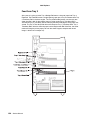
Feed from Tray 3 . . . . . . . . . . . . . . . . . . . . . . . . . . . . . . . . . . . . . . . . . . . . . . . 1-56
Tray 3 Paper Path Components . . . . . . . . . . . . . . . . . . . . . . . . . . . . . . . . . . . 1-57
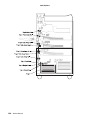
Feed from Tray 4 . . . . . . . . . . . . . . . . . . . . . . . . . . . . . . . . . . . . . . . . . . . . . . . 1-57
Tray 4 Paper Path Components . . . . . . . . . . . . . . . . . . . . . . . . . . . . . . . . . . . 1-59
Feed from Tray 5 . . . . . . . . . . . . . . . . . . . . . . . . . . . . . . . . . . . . . . . . . . . . . . . 1-61
Tray 5 Paper Path Components . . . . . . . . . . . . . . . . . . . . . . . . . . . . . . . . . . . 1-62
High Capacity Feeder General Specifications . . . . . . . . . . . . . . . . . . . . . . . . 1-64
Glossary of Terms, Acronyms, and Abbreviations . . . . . . . . . . . . . . . . . . . . . . 1-65
Diagnostic Information . . . . . . . . . . . . . . . . . . . . . . . . . . . . . . . . . . . . . . . . . . . . . . . . . . . . . . . 2-1
Start . . . . . . . . . . . . . . . . . . . . . . . . . . . . . . . . . . . . . . . . . . . . . . . . . . . . . . . . . . . . . 2-1
Envelope Feeder . . . . . . . . . . . . . . . . . . . . . . . . . . . . . . . . . . . . . . . . . . . . . . . . . . . 2-2
Envelope Feeder Error Code Table . . . . . . . . . . . . . . . . . . . . . . . . . . . . . . . . . . 2-2
Envelope Feeder Symptom Table . . . . . . . . . . . . . . . . . . . . . . . . . . . . . . . . . . . 2-2
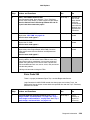
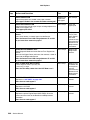
Envelope Feeder Error Code Service Checks . . . . . . . . . . . . . . . . . . . . . . . . . 2-3
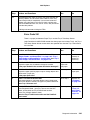
Envelope Feeder Symptom Service Checks . . . . . . . . . . . . . . . . . . . . . . . . . . . 2-7
Duplex . . . . . . . . . . . . . . . . . . . . . . . . . . . . . . . . . . . . . . . . . . . . . . . . . . . . . . . . . . . 2-8
Duplex Error Code Table . . . . . . . . . . . . . . . . . . . . . . . . . . . . . . . . . . . . . . . . . . 2-8
Duplex Symptom Table . . . . . . . . . . . . . . . . . . . . . . . . . . . . . . . . . . . . . . . . . . . 2-9
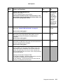
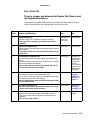
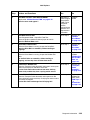
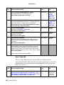
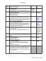
Duplex Error Code Service Checks . . . . . . . . . . . . . . . . . . . . . . . . . . . . . . . . . 2-9
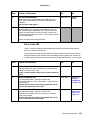
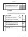
Error Code 997 . . . . . . . . . . . . . . . . . . . . . . . . . . . . . . . . . . . . . . . . . . . . . . . . 2-17
Duplex Symptom Service Checks . . . . . . . . . . . . . . . . . . . . . . . . . . . . . . . . . . 2-18
Mailbox . . . . . . . . . . . . . . . . . . . . . . . . . . . . . . . . . . . . . . . . . . . . . . . . . . . . . . . . . . 2-19
Mailbox Error Code Table . . . . . . . . . . . . . . . . . . . . . . . . . . . . . . . . . . . . . . . . 2-19
Mailbox Symptom Table . . . . . . . . . . . . . . . . . . . . . . . . . . . . . . . . . . . . . . . . . 2-20
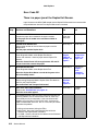
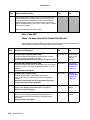
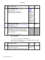
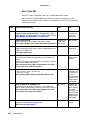
Mailbox Error Code Service Checks . . . . . . . . . . . . . . . . . . . . . . . . . . . . . . . . 2-20
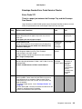
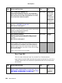
Error Code 996 . . . . . . . . . . . . . . . . . . . . . . . . . . . . . . . . . . . . . . . . . . . . . . . . 2-29
Mailbox Symptom Service Checks . . . . . . . . . . . . . . . . . . . . . . . . . . . . . . . . . 2-30
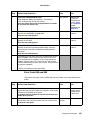
High Capacity Feeder . . . . . . . . . . . . . . . . . . . . . . . . . . . . . . . . . . . . . . . . . . . . . . 2-32
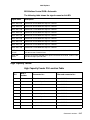
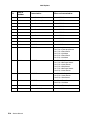
High Capacity Feeder Error Code Table . . . . . . . . . . . . . . . . . . . . . . . . . . . . . 2-32
High Capacity Feeder Symptom Table . . . . . . . . . . . . . . . . . . . . . . . . . . . . . . 2-33
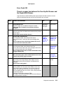
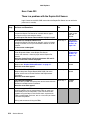
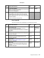
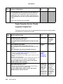
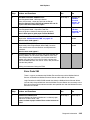
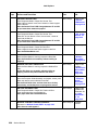
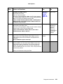
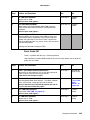
High Capacity Feeder Error Code Service Checks . . . . . . . . . . . . . . . . . . . . . 2-33
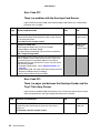
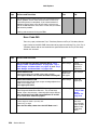
Error Code 993 and 994 . . . . . . . . . . . . . . . . . . . . . . . . . . . . . . . . . . . . . . . . . 2-51
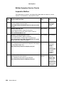
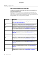
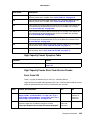
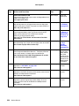
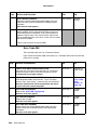
High Capacity Feeder Symptom Service Checks . . . . . . . . . . . . . . . . . . . . . . 2-52
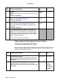
Diagnostic Aids. . . . . . . . . . . . . . . . . . . . . . . . . . . . . . . . . . . . . . . . . . . . . . . . . . . . . . . . . . . . . . . . 3-1
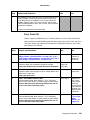
Envelope Feeder Tests . . . . . . . . . . . . . . . . . . . . . . . . . . . . . . . . . . . . . . . . . . . . . . 3-1
Feed Test . . . . . . . . . . . . . . . . . . . . . . . . . . . . . . . . . . . . . . . . . . . . . . . . . . . . . 3-1
Sensor Test . . . . . . . . . . . . . . . . . . . . . . . . . . . . . . . . . . . . . . . . . . . . . . . . . . . . 3-1

vi Contents
4025 Options
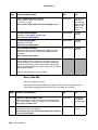
Duplex Tests . . . . . . . . . . . . . . . . . . . . . . . . . . . . . . . . . . . . . . . . . . . . . . . . . . . . . . 3-2
Feed Test . . . . . . . . . . . . . . . . . . . . . . . . . . . . . . . . . . . . . . . . . . . . . . . . . . . . . . 3-2
Sensor Test . . . . . . . . . . . . . . . . . . . . . . . . . . . . . . . . . . . . . . . . . . . . . . . . . . . . 3-2
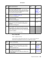
Mailbox Tests . . . . . . . . . . . . . . . . . . . . . . . . . . . . . . . . . . . . . . . . . . . . . . . . . . . . . 3-3
Feed Test . . . . . . . . . . . . . . . . . . . . . . . . . . . . . . . . . . . . . . . . . . . . . . . . . . . . . . 3-3
Feed All Bins Test . . . . . . . . . . . . . . . . . . . . . . . . . . . . . . . . . . . . . . . . . . . . . . . 3-3
Sensor Test . . . . . . . . . . . . . . . . . . . . . . . . . . . . . . . . . . . . . . . . . . . . . . . . . . . . 3-4
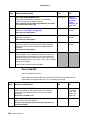
High Capacity Feeder Tests . . . . . . . . . . . . . . . . . . . . . . . . . . . . . . . . . . . . . . . . . 3-5
Feed Test . . . . . . . . . . . . . . . . . . . . . . . . . . . . . . . . . . . . . . . . . . . . . . . . . . . . . . 3-5
Sensor Test . . . . . . . . . . . . . . . . . . . . . . . . . . . . . . . . . . . . . . . . . . . . . . . . . . . . 3-6
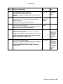
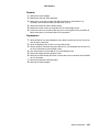
Repair Information . . . . . . . . . . . . . . . . . . . . . . . . . . . . . . . . . . . . . . . . . . . . . . . . . . . . . . . . . . . 4-1
Preparation . . . . . . . . . . . . . . . . . . . . . . . . . . . . . . . . . . . . . . . . . . . . . . . . . . . . 4-1
Work Notes . . . . . . . . . . . . . . . . . . . . . . . . . . . . . . . . . . . . . . . . . . . . . . . . . . . . 4-1
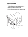
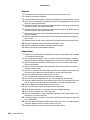
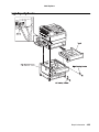
Removal and Replacement Procedures . . . . . . . . . . . . . . . . . . . . . . . . . . . . . . . . 4-2
Envelope Feeder . . . . . . . . . . . . . . . . . . . . . . . . . . . . . . . . . . . . . . . . . . . . . . . . . . . 4-2
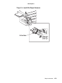
Duplex Unit Assembly . . . . . . . . . . . . . . . . . . . . . . . . . . . . . . . . . . . . . . . . . . . . . . 4-3
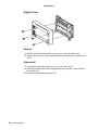
Duplex Cover . . . . . . . . . . . . . . . . . . . . . . . . . . . . . . . . . . . . . . . . . . . . . . . . . . . 4-4
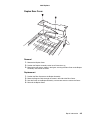
Duplex Rear Cover . . . . . . . . . . . . . . . . . . . . . . . . . . . . . . . . . . . . . . . . . . . . . . 4-5
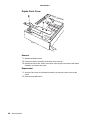
Duplex Front Cover . . . . . . . . . . . . . . . . . . . . . . . . . . . . . . . . . . . . . . . . . . . . . . 4-6
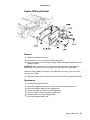
Duplex PWB and Bracket . . . . . . . . . . . . . . . . . . . . . . . . . . . . . . . . . . . . . . . . . 4-7
Duplex Wait Clutch . . . . . . . . . . . . . . . . . . . . . . . . . . . . . . . . . . . . . . . . . . . . . . 4-8
Duplex Drive Assembly . . . . . . . . . . . . . . . . . . . . . . . . . . . . . . . . . . . . . . . . . . . 4-9
Duplex Exit Sensor . . . . . . . . . . . . . . . . . . . . . . . . . . . . . . . . . . . . . . . . . . . . . 4-10
Duplex Exit Gate Solenoid . . . . . . . . . . . . . . . . . . . . . . . . . . . . . . . . . . . . . . . 4-11
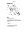
Exit Roll . . . . . . . . . . . . . . . . . . . . . . . . . . . . . . . . . . . . . . . . . . . . . . . . . . . . . 4-12
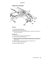
Duplex Wait Sensor . . . . . . . . . . . . . . . . . . . . . . . . . . . . . . . . . . . . . . . . . . . . 4-14
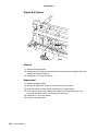
Duplex Interlock Switch . . . . . . . . . . . . . . . . . . . . . . . . . . . . . . . . . . . . . . . . . 4-15
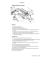
Exit Roll Belt . . . . . . . . . . . . . . . . . . . . . . . . . . . . . . . . . . . . . . . . . . . . . . . . . . 4-16
Duplex Pinch Roll . . . . . . . . . . . . . . . . . . . . . . . . . . . . . . . . . . . . . . . . . . . . . . 4-17
Inner Chute Assembly . . . . . . . . . . . . . . . . . . . . . . . . . . . . . . . . . . . . . . . . . . 4-18
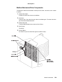
Mailbox . . . . . . . . . . . . . . . . . . . . . . . . . . . . . . . . . . . . . . . . . . . . . . . . . . . . . . . . . . 4-19
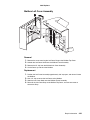
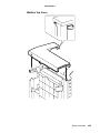
Mailbox Left Cover Assembly . . . . . . . . . . . . . . . . . . . . . . . . . . . . . . . . . . . . . 4-21
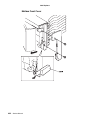
Mailbox Front Cover . . . . . . . . . . . . . . . . . . . . . . . . . . . . . . . . . . . . . . . . . . . . 4-22
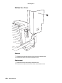
Mailbox Rear Cover . . . . . . . . . . . . . . . . . . . . . . . . . . . . . . . . . . . . . . . . . . . . 4-24
Mailbox Top Cover . . . . . . . . . . . . . . . . . . . . . . . . . . . . . . . . . . . . . . . . . . . . . 4-25
Actuator Cover Assembly . . . . . . . . . . . . . . . . . . . . . . . . . . . . . . . . . . . . . . . . 4-27
Bin 10 Jam Sensor . . . . . . . . . . . . . . . . . . . . . . . . . . . . . . . . . . . . . . . . . . . . . 4-29
BIN 10 Tray Assembly . . . . . . . . . . . . . . . . . . . . . . . . . . . . . . . . . . . . . . . . . . 4-30
Mailbox Drive Belt . . . . . . . . . . . . . . . . . . . . . . . . . . . . . . . . . . . . . . . . . . . . . . 4-32
BIN Trays 1 - 9 Assemblies . . . . . . . . . . . . . . . . . . . . . . . . . . . . . . . . . . . . . . . 4-34
Gate Solenoids 1 - 9 . . . . . . . . . . . . . . . . . . . . . . . . . . . . . . . . . . . . . . . . . . . . 4-36

Contents vii
4025 Options
Mailbox Exit Roll and Bin Gate . . . . . . . . . . . . . . . . . . . . . . . . . . . . . . . . . . . . 4-38
Mailbox Entrance Sensor . . . . . . . . . . . . . . . . . . . . . . . . . . . . . . . . . . . . . . . . 4-39
IN Gate Solenoid . . . . . . . . . . . . . . . . . . . . . . . . . . . . . . . . . . . . . . . . . . . . . . 4-40
Vertical LED/Sensor . . . . . . . . . . . . . . . . . . . . . . . . . . . . . . . . . . . . . . . . . . . . 4-42
Mailbox Control PWB . . . . . . . . . . . . . . . . . . . . . . . . . . . . . . . . . . . . . . . . . . . 4-44
Mailbox Drive Motor . . . . . . . . . . . . . . . . . . . . . . . . . . . . . . . . . . . . . . . . . . . . 4-46
Full Stack Actuator . . . . . . . . . . . . . . . . . . . . . . . . . . . . . . . . . . . . . . . . . . . . . 4-48
Rear Lower Cover . . . . . . . . . . . . . . . . . . . . . . . . . . . . . . . . . . . . . . . . . . . . . 4-49
IN Gate . . . . . . . . . . . . . . . . . . . . . . . . . . . . . . . . . . . . . . . . . . . . . . . . . . . . . . 4-50
Lower Chute . . . . . . . . . . . . . . . . . . . . . . . . . . . . . . . . . . . . . . . . . . . . . . . . . . 4-52
Mailbox Interlock Switch . . . . . . . . . . . . . . . . . . . . . . . . . . . . . . . . . . . . . . . . . 4-53
Transport Guide Assembly . . . . . . . . . . . . . . . . . . . . . . . . . . . . . . . . . . . . . . . 4-54
High Capacity Feeder . . . . . . . . . . . . . . . . . . . . . . . . . . . . . . . . . . . . . . . . . . . . . 4-55
HCF Rear Cover . . . . . . . . . . . . . . . . . . . . . . . . . . . . . . . . . . . . . . . . . . . . . . 4-57
HCF Left Cover . . . . . . . . . . . . . . . . . . . . . . . . . . . . . . . . . . . . . . . . . . . . . . . 4-58
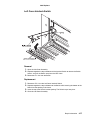
Left Cover Assembly . . . . . . . . . . . . . . . . . . . . . . . . . . . . . . . . . . . . . . . . . . . 4-59
Right Cover . . . . . . . . . . . . . . . . . . . . . . . . . . . . . . . . . . . . . . . . . . . . . . . . . . 4-60
Front Cover BTM . . . . . . . . . . . . . . . . . . . . . . . . . . . . . . . . . . . . . . . . . . . . . . 4-61
HCF Feed Motor . . . . . . . . . . . . . . . . . . . . . . . . . . . . . . . . . . . . . . . . . . . . . . 4-62
HCF Drive Belt . . . . . . . . . . . . . . . . . . . . . . . . . . . . . . . . . . . . . . . . . . . . . . . . 4-64
HCF PWB . . . . . . . . . . . . . . . . . . . . . . . . . . . . . . . . . . . . . . . . . . . . . . . . . . . . 4-66
Lift Motor . . . . . . . . . . . . . . . . . . . . . . . . . . . . . . . . . . . . . . . . . . . . . . . . . . . . . 4-67
Tray 3 Paper Size Sensor PWB . . . . . . . . . . . . . . . . . . . . . . . . . . . . . . . . . . . 4-68
Tray 4 and Tray 5 Paper Size Sensor PWBs . . . . . . . . . . . . . . . . . . . . . . . . . 4-69
Trays 3, 4, and 5 Feed Clutches . . . . . . . . . . . . . . . . . . . . . . . . . . . . . . . . . . . 4-70
Trays 3, 4, and 5 No Paper Actuators . . . . . . . . . . . . . . . . . . . . . . . . . . . . . . . 4-71
Trays 3, 4, and 5 No Paper Sensors . . . . . . . . . . . . . . . . . . . . . . . . . . . . . . . . 4-73
Trays 3, 4, and 5 Paper Level Sensors . . . . . . . . . . . . . . . . . . . . . . . . . . . . . . 4-75
Left Cover Interlock Switch . . . . . . . . . . . . . . . . . . . . . . . . . . . . . . . . . . . . . . . 4-77
Tray 3 Take Away Sensor . . . . . . . . . . . . . . . . . . . . . . . . . . . . . . . . . . . . . . . . 4-78
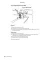
Tray 3 Feeder Assembly . . . . . . . . . . . . . . . . . . . . . . . . . . . . . . . . . . . . . . . . . 4-79
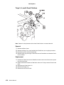
Tray 3 Retard Assembly . . . . . . . . . . . . . . . . . . . . . . . . . . . . . . . . . . . . . . . . . 4-81
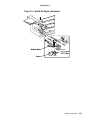
Tray 3 Nudger, Feeder, and Retard Rolls . . . . . . . . . . . . . . . . . . . . . . . . . . . . 4-84
HCF Tray 4 . . . . . . . . . . . . . . . . . . . . . . . . . . . . . . . . . . . . . . . . . . . . . . . . . . . 4-86
Tray 4 Front Cover . . . . . . . . . . . . . . . . . . . . . . . . . . . . . . . . . . . . . . . . . . . . . 4-87
Tray 4 Take Away Sensor . . . . . . . . . . . . . . . . . . . . . . . . . . . . . . . . . . . . . . . . 4-88
Tray 4 Take Away Roll . . . . . . . . . . . . . . . . . . . . . . . . . . . . . . . . . . . . . . . . . . 4-89
Tray 4 Feeder Assembly . . . . . . . . . . . . . . . . . . . . . . . . . . . . . . . . . . . . . . . . . 4-92
Tray 4 Retard Assembly . . . . . . . . . . . . . . . . . . . . . . . . . . . . . . . . . . . . . . . . . 4-94
Tray 4 Feed, Nudger, and Retard Rolls . . . . . . . . . . . . . . . . . . . . . . . . . . . . . 4-96
HCF Tray 5 . . . . . . . . . . . . . . . . . . . . . . . . . . . . . . . . . . . . . . . . . . . . . . . . . . . 4-98
Tray 5 Front Cover . . . . . . . . . . . . . . . . . . . . . . . . . . . . . . . . . . . . . . . . . . . . . 4-99
Tray 5 Feeder Assembly . . . . . . . . . . . . . . . . . . . . . . . . . . . . . . . . . . . . . . . . 4-100

viii Contents
4025 Options
Tray 5 Retard Assembly . . . . . . . . . . . . . . . . . . . . . . . . . . . . . . . . . . . . . . . . 4-102
Tray 5 Feed, Nudger, and Retard Rolls . . . . . . . . . . . . . . . . . . . . . . . . . . . . . 4-104
Connector Locations. . . . . . . . . . . . . . . . . . . . . . . . . . . . . . . . . . . . . . . . . . . . . . . . . . . . . . . . . 5-1
Envelope Feeder . . . . . . . . . . . . . . . . . . . . . . . . . . . . . . . . . . . . . . . . . . . . . . . . . . . 5-1
Envelope Feeder P/J Location Table . . . . . . . . . . . . . . . . . . . . . . . . . . . . . . . . . 5-1
Envelope Feeder P/J Location Map 1 . . . . . . . . . . . . . . . . . . . . . . . . . . . . . . . . 5-2
Envelope Feeder Wiring Diagrams . . . . . . . . . . . . . . . . . . . . . . . . . . . . . . . . . . 5-2
Duplex . . . . . . . . . . . . . . . . . . . . . . . . . . . . . . . . . . . . . . . . . . . . . . . . . . . . . . . . . . . 5-6
Duplex P/J Location Table . . . . . . . . . . . . . . . . . . . . . . . . . . . . . . . . . . . . . . . . . 5-6
Duplex P/J Location Map 1 . . . . . . . . . . . . . . . . . . . . . . . . . . . . . . . . . . . . . . . . 5-7
Duplex Wiring Diagrams . . . . . . . . . . . . . . . . . . . . . . . . . . . . . . . . . . . . . . . . . . 5-8
Mailbox . . . . . . . . . . . . . . . . . . . . . . . . . . . . . . . . . . . . . . . . . . . . . . . . . . . . . . . . . . 5-11
Mailbox P/J Location Table . . . . . . . . . . . . . . . . . . . . . . . . . . . . . . . . . . . . . . . 5-11
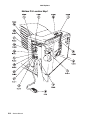
Mailbox P/J Location Map 1 . . . . . . . . . . . . . . . . . . . . . . . . . . . . . . . . . . . . . . . 5-12
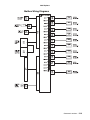
Mailbox Wiring Diagrams . . . . . . . . . . . . . . . . . . . . . . . . . . . . . . . . . . . . . . . . . 5-13
High Capacity Feeder . . . . . . . . . . . . . . . . . . . . . . . . . . . . . . . . . . . . . . . . . . . . . . 5-17
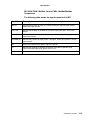
High Capacity Feeder P/J Location Table . . . . . . . . . . . . . . . . . . . . . . . . . . . . 5-17
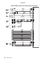
High Capacity Feeder P/J Location Map 1 . . . . . . . . . . . . . . . . . . . . . . . . . . . 5-19
High Capacity Feeder P/J Location Map 2 . . . . . . . . . . . . . . . . . . . . . . . . . . . 5-20
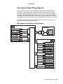
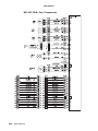
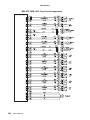
High Capacity Feeder Wiring Diagrams . . . . . . . . . . . . . . . . . . . . . . . . . . . . . 5-21
Preventative Maintenance . . . . . . . . . . . . . . . . . . . . . . . . . . . . . . . . . . . . . . . . . . . . . . . . . . . 6-1
Parts Catalog. . . . . . . . . . . . . . . . . . . . . . . . . . . . . . . . . . . . . . . . . . . . . . . . . . . . . . . . . . . . . . . . . . 7-1
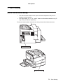
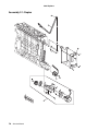
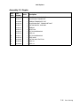
How to Use the Parts Catalog . . . . . . . . . . . . . . . . . . . . . . . . . . . . . . . . . . . . . . . . 7-1
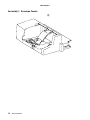
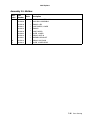
Assembly 1: Envelope Feeder . . . . . . . . . . . . . . . . . . . . . . . . . . . . . . . . . . . . . . 7-2
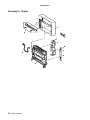
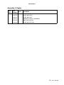
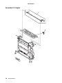
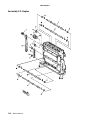
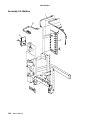
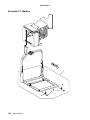
Assembly 2: Duplex. . . . . . . . . . . . . . . . . . . . . . . . . . . . . . . . . . . . . . . . . . . . . . . 7-4
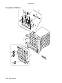
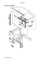
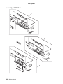
Assembly 3: Mailbox . . . . . . . . . . . . . . . . . . . . . . . . . . . . . . . . . . . . . . . . . . . . . 7-14
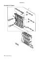
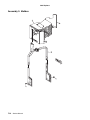
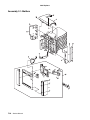
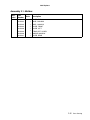
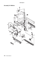
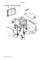
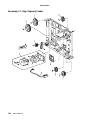
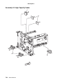
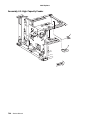
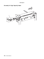
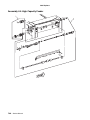
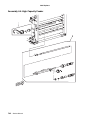
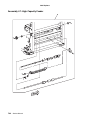
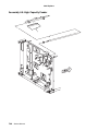
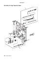
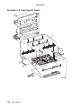
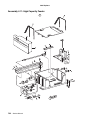
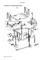
Assembly 4: High Capacity Feeder . . . . . . . . . . . . . . . . . . . . . . . . . . . . . . . . . 7-30
Index . . . . . . . . . . . . . . . . . . . . . . . . . . . . . . . . . . . . . . . . . . . . . . . . . . . . . . . . . . . . . . . . . . . . . . . . . . . . I-1

Preface ix
4025 Options
Preface
This manual describes the options for the Lexmark
TM
W820 printer: Envelope Feeder,
Duplex Unit, Mailbox, and High Capacity Feeder. It contains maintenance procedures for
service personnel only and is divided into the following chapters:
1. General Information contains a general description of the printer options and the
maintenance approach used to repair them. Special tools and test equipment are
listed, as well as general environmental and safety instructions.
2. Diagnostic Information contains an error indicator table, symptom tables, and
service checks used to isolate failing field replaceable units (FRUs).
3. Diagnostic Aids contains tests and checks used to locate or repeat symptoms of
printer option problems.
4. Repair Information provides instructions for removing and installing FRUs.
5. Connector Locations uses illustrations to identify the connector locations and test
points on the options.
6. Preventive Maintenance contains the lubrication specifications and
recommendations to prevent problems.
7. Parts Catalog contains illustrations and part numbers for individual FRUs.

x Safety Information
4025 Options
Safety Information
• This product is designed, tested and approved to meet strict global safety standards
with the use of specific Lexmark components. The safety features of some parts may
not always be obvious. Lexmark is not responsible for the use of other replacement
parts.
• The maintenance information for this product has been prepared for use by a
professional service person and is not intended to be used by others.
• There may be an increased risk of electric shock and personal injury during
disassembly and servicing of this product. Professional service personnel should
understand this and take necessary precautions.
Consignes de Sécurité
• Ce produit a été conçu, testé et approuvé pour respecter les normes strictes de
sécurité globale lors de l'utilisation de composants Lexmark spécifiques. Les
caractéristiques de sécurité de certains éléments ne sont pas toujours évidentes.
Lexmark ne peut être tenu responsable de l'utilisation d'autres pièces de rechange.
• Les consignes d'entretien et de réparation de ce produit s'adressent uniquement à
un personnel de maintenance qualifié.
• Le démontage et l'entretien de ce produit pouvant présenter certains risques
électriques, le personnel d'entretien qualifié devra prendre toutes les précautions
nécessaires.
Norme di sicurezza
• Il prodotto è stato progettato, testato e approvato in conformità a severi standard di
sicurezza e per l’utilizzo con componenti Lexmark specifici. Le caratteristiche di
sicurezza di alcune parti non sempre sono di immediata comprensione. Lexmark
non è responsabile per l’utilizzo di parti di ricambio di altri produttori.
• Le informazioni riguardanti la manutenzione di questo prodotto sono indirizzate
soltanto al personale di assistenza autorizzato.
• Durante lo smontaggio e la manutenzione di questo prodotto, il rischio di subire
scosse elettriche e danni alla persona è più elevato. Il personale di assistenza
autorizzato, deve, quindi, adottare le precauzioni necessarie.

Safety Information xi
4025 Options
Sicherheitshinweise
• Dieses Produkt und die zugehörigen Komponenten wurden entworfen und getestet,
um beim Einsatz die weltweit gültigen Sicherheitsanforderungen zu erfüllen. Die
sicherheitsrelevanten Funktionen der Bauteile und Optionen sind nicht immer
offensichtlich. Sofern Teile eingesetzt werden, die nicht von Lexmark sind, wird von
Lexmark keinerlei Verantwortung oder Haftung für dieses Produkt übernommen.
• Die Wartungsinformationen für dieses Produkt sind ausschließlich für die
Verwendung durch einen Wartungsfachmann bestimmt.
• Während des Auseinandernehmens und der Wartung des Geräts besteht ein
zusätzliches Risiko eines elektrischen Schlags und körperlicher Verletzung. Das
zuständige Fachpersonal sollte entsprechende Vorsichtsmaßnahmen treffen.
Pautas de Seguridad
• Este producto se ha diseñado, verificado y aprobado para cumplir los más estrictos
estándares de seguridad global usando los componentes específicos de Lexmark.
Puede que las características de seguridad de algunas piezas no sean siempre
evidentes. Lexmark no se hace responsable del uso de otras piezas de recambio.
• La información sobre el mantenimiento de este producto está dirigida
exclusivamente al personal cualificado de mantenimiento.
• Existe mayor riesgo de descarga eléctrica y de daños personales durante el
desmontaje y la reparación de la máquina. El personal cualificado debe ser
consciente de este peligro y tomar las precauciones necesarias.
Informações de Segurança
• Este produto foi concebido, testado e aprovado para satisfazer os padrões globais
de segurança na utilização de componentes específicos da Lexmark. As funções de
segurança de alguns dos componentes podem não ser sempre óbvias. A Lexmark
não é responsável pela utilização de outros componentes de substituição.
• As informações de segurança relativas a este produto destinam-se a profissionais
destes serviços e não devem ser utilizadas por outras pessoas.
• Risco de choques eléctricos e ferimentos graves durante a desmontagem e
manutenção deste produto. Os profissionais destes serviços devem estar avisados
deste facto e tomar os cuidados necessários.

xii Safety Information
4025 Options
Informació de Seguretat
• Aquest producte està dissenyat, comprovat i aprovat per tal d'acomplir les estrictes
normes de seguretat globals amb la utililització de components específics de
Lexmark. Les característiques de seguretat d'algunes peces pot ser que no sempre
siguin òbvies. Lexmark no es responsabilitza de l'us d'altres peces de recanvi.
• La informació pel manteniment d’aquest producte està orientada exclusivament a
professionals i no està destinada a ningú que no ho sigui.
• El risc de xoc elèctric i de danys personals pot augmentar durant el procés de
desmuntatge i de servei d’aquest producte. El personal professional ha d’estar-ne
assabentat i prendre les mesures convenients.

General Information 1-1
4025 Options
1. General Information
Maintenance Approach
The diagnostic information in this manual leads you to the correct field replaceable unit
(FRU) or part for the Envelope Feeder, Duplex, Mailbox, and High Capacity Feeder
options. Use the appropriate error code table, symptom table, error code service checks
and symptom service checks to determine the corrective action necessary to repair the
failing option. After you complete the repair, perform tests as needed to verify the repair.
Tools Required For Service
The removal and replacement procedures described in this manual require the following
tools and equipment:
• Magnetic tip Phillips screwdrivers, large and small
• Flat-blade screwdrivers
• Analog volt ohmmeter (a digital volt ohmmeter may also be used)
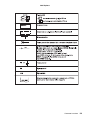
Symbols Used in this Manual
Various symbols are used throughout this manual to either provide additional information
on a specific topic or to warn of possible danger that might be present during a procedure
or action. Be aware of all symbols when they are used, and always read NOTE,
CAUTION, and WARNING messages.
Note: A NOTE may indicate an operating or maintenance procedure, practice, or
condition that is necessary to efficiently accomplish a task. A NOTE may also provide
additional information related to a specific subject or add a comment on the results
achieved through a previous action.
WARNING: A WARNING indicates an operating or maintenance procedure, practice, or
condition that, if not strictly observed, could result in damage to, or destruction of,
equipment.
CAUTION: A CAUTION indicates an operating or maintenance procedure, practice, or
condition that, if not strictly observed, could result in injury.
Safety Details
Follow all safety instructions to prevent accidents while servicing the printer and attached
options. Always be aware of the potential dangers that are present when you are working
with electrical or mechanical equipment.

1-2 Service Manual
4025 Options
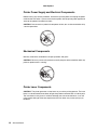
Printer Power Supply and Electrical Components
Before starting any service procedure, switch off the printer power and unplug the power
cord from the wall outlet. If you must service the options with the printer power applied, be
aware of the potential for electrical shock.
CAUTION: Do not touch any electrical component unless you are instructed to do so by
a service procedure.
Mechanical Components
Manually rotate drive assemblies to inspect sprockets and gears.
CAUTION: Do not try to manually rotate or manually stop the drive assemblies while any
printer or option motor is running.
Printer Laser Components
CAUTION: The printer generates a laser beam as part of the printing process. The laser
beam is a concentrated narrow beam of light that produces extreme heat at its focal point.
The laser beam in this printer is invisible. Although you cannot see the beam, it can still
cause severe damage. Direct eye exposure to the laser beam may cause eye injury or
blindness.

General Information 1-3
4025 Options
To avoid permanent eye damage, follow these directions:
• Before starting any service procedure, switch off the printer power and unplug the
power cord from the AC wall outlet.
• Do not disassemble the printer Printhead Assembly or any laser component that
displays a Laser Warning sticker.
• Use caution when you are working around the printer Printhead Assembly or when
you are performing laser related troubleshooting or repair procedures.
• Never place a mirror or a reflective tool or object in the laser beam path.
• Do not disassemble the printer in such a way that the laser beam can exit the print
engine during a print cycle.
Printer Fuser Components
CAUTION: This printer uses heat to fuse the toner image to a sheet paper. The printer
Fuser Assembly is very hot. Switch off printer power and wait at least 45 minutes for the
fuser to cool before you attempt to service the printer Fuser Assembly or adjacent
components.
Safety Components
Make sure covers and panel are in place and that all interlock switches are all functioning
correctly after you have completed a printer or option service call. If you bypass, or cheat,
an interlock switch during a service call, use extreme caution when working on or around
the printer or options.
Caution Labels
Throughout the equipment, warning labels are displayed on potentially dangerous
components. When you service the printer and options, check to make sure that all
caution labels are in place.
Most importantly, read and obey all posted caution labels.

1-4 Service Manual
4025 Options
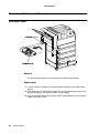
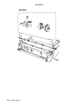
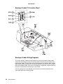
Envelope Feeder
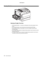
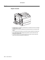
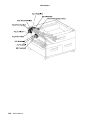
Envelope Feeder Overview
• The Envelope Feeder is a customer installed option that feeds envelopes into the
printer.
• The Envelope Feeder is easily installed in place of the printer MP Feeder.
• The printer base engine LVPS provides all of the DC voltages required by the
Envelope Feeder.
• One +24VDC motor inside the Envelope Feeder provides all of the mechanical drive
required for operation.
• One PWB and three sensors inside the Envelope Feeder provide all of the control
and paper path monitoring required for operation.

General Information 1-5
4025 Options
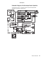
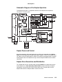
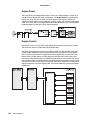
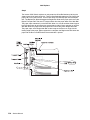
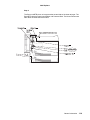
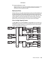
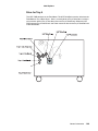
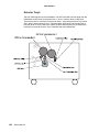
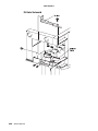
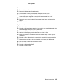
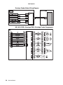
Schematic Diagram of the Envelope Feeder Operation
The following illustration is a simplified schematic of printer Envelope Feeder
components, subsystems, and paper paths.

1-6 Service Manual
4025 Options
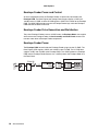
Envelope Feeder Power and Control
All active components within the Envelope Feeder are electrically connected to the
Envelope PWB. The Base Engine Low Voltage Power Supply supplies +5VDC and
+24VDC to the I/O PWB, and the I/O PWB supplies +5VDC and +24VDC to the Envelope
PWB. The MCU PWB provides most of the Envelope Feeder logic, while the Envelope
PWB executes the MCU commands.
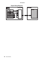
Envelope Feeder Drive Generation and Distribution
The printer Envelope Feeder has one +24VDC motor, the Envelope Motor, that supplies
drive to the entire Envelope Feeder. A Gear Assembly and Feed Clutch controls and
transfers motor drive to Envelope Feeder components.
Envelope Feeder Power
The Envelope PWB, located inside the Envelope Feeder, plugs into the I/O PWB. The
Base Engine LVPS supplies +5VDC and +24VDC to the I/O PWB. The I/O PWB then
supplies +5VDC and +24VDC to the Envelope PWB. The +5VDC powers the Envelope
PWB and the Envelope Feeder Sensors, the +24VDC powers the Envelope Motor and
the Feed Clutch.

General Information 1-7
4025 Options
Envelope Feeder Control
Envelope Feeder Control is a broad term used to describe the printer resources that
monitor and control the actions and operations of the printer and the Envelope Feeder;
from envelope feed to Envelope Feeder error detection.
The center of Envelope Feeder control is the Envelope PWB. The MCU PWB provides
the logic and information processing necessary for the printer to function, and the
Envelope PWB provides the logic and information processing necessary for the Envelope
Feeder to function. Every electrical component within the Envelope Feeder is connected
to the Envelope PWB. Sensors in the Envelope Feeder send status information to the
Envelope PWB. The Envelope PWB processes that information and shares it with the
MCU PWB. Acting on the results of the processing, the Envelope PWB sends commands
to the various Envelope Feeder components; switching off the motor or switching on the
Feed Clutch.

1-8 Service Manual
4025 Options
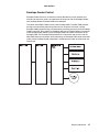
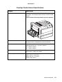
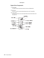
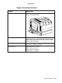
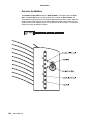
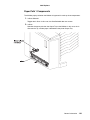
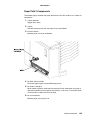
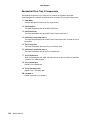
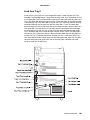
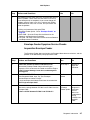
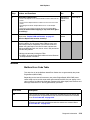
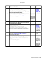
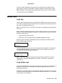
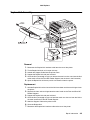
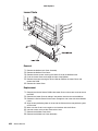
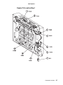
Envelope Feeder Control Components
Envelope Feeder Control is made up of four major components.
1. Envelope Feeder PWB
The Envelope Feeder PWB controls all Envelope Feeder functions, executes
commands sent by the MCU PWB, and sends information back to the MCU PWB.
2. No Paper Sensor
Monitors the envelope level in the Envelope tray.
3. Size Sensor
Monitors the envelope size loaded in the Envelope tray.
4. Feed Sensor
Monitors envelope travel out of the Envelope Feeder.
Monitors paper entering the Envelope Feeder from the printer.
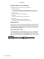
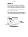
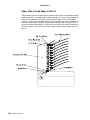
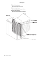
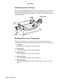
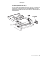
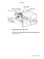
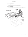
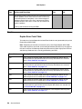
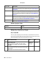
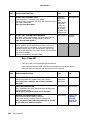
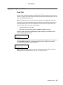
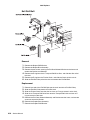
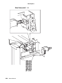
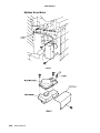
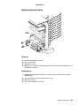
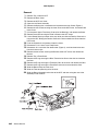
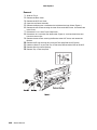
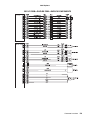
Mechanical Drive
Mechanical Drive is a term used to describe both the rotation of the Envelope Motor and
the action of the gears and rollers used to transmit motor rotation to the drive rolls within
the Envelope Feeder. The purpose of Mechanical Drive within the Envelope Feeder is to
provide the mechanical energy needed to drive an envelope from the Envelope Feeder
tray and into the printer base engine.
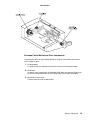
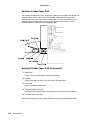
Drive for the Envelope Feeder
The Envelope PWB controls the Envelope Motor. The Motor rotates the Drive Gears.
When the Envelope PWB switches on the Envelope Motor, the Motor rotates the Drive
Gears. When the Envelope PWB actuates the Feed Clutch, the Clutch transmits drive to
the Envelope Feed and Transport Roll. The Friction Clutch transmits drive to the Retard
Roll.
La pagina si sta caricando...
La pagina si sta caricando...
La pagina si sta caricando...
La pagina si sta caricando...
La pagina si sta caricando...
La pagina si sta caricando...
La pagina si sta caricando...
La pagina si sta caricando...
La pagina si sta caricando...
La pagina si sta caricando...
La pagina si sta caricando...
La pagina si sta caricando...
La pagina si sta caricando...
La pagina si sta caricando...
La pagina si sta caricando...
La pagina si sta caricando...
La pagina si sta caricando...
La pagina si sta caricando...
La pagina si sta caricando...
La pagina si sta caricando...
La pagina si sta caricando...
La pagina si sta caricando...
La pagina si sta caricando...
La pagina si sta caricando...
La pagina si sta caricando...
La pagina si sta caricando...
La pagina si sta caricando...
La pagina si sta caricando...
La pagina si sta caricando...
La pagina si sta caricando...
La pagina si sta caricando...
La pagina si sta caricando...
La pagina si sta caricando...
La pagina si sta caricando...
La pagina si sta caricando...
La pagina si sta caricando...
La pagina si sta caricando...
La pagina si sta caricando...
La pagina si sta caricando...
La pagina si sta caricando...
La pagina si sta caricando...
La pagina si sta caricando...
La pagina si sta caricando...
La pagina si sta caricando...
La pagina si sta caricando...
La pagina si sta caricando...
La pagina si sta caricando...
La pagina si sta caricando...
La pagina si sta caricando...
La pagina si sta caricando...
La pagina si sta caricando...
La pagina si sta caricando...
La pagina si sta caricando...
La pagina si sta caricando...
La pagina si sta caricando...
La pagina si sta caricando...
La pagina si sta caricando...
La pagina si sta caricando...
La pagina si sta caricando...
La pagina si sta caricando...
La pagina si sta caricando...
La pagina si sta caricando...
La pagina si sta caricando...
La pagina si sta caricando...
La pagina si sta caricando...
La pagina si sta caricando...
La pagina si sta caricando...
La pagina si sta caricando...
La pagina si sta caricando...
La pagina si sta caricando...
La pagina si sta caricando...
La pagina si sta caricando...
La pagina si sta caricando...
La pagina si sta caricando...
La pagina si sta caricando...
La pagina si sta caricando...
La pagina si sta caricando...
La pagina si sta caricando...
La pagina si sta caricando...
La pagina si sta caricando...
La pagina si sta caricando...
La pagina si sta caricando...
La pagina si sta caricando...
La pagina si sta caricando...
La pagina si sta caricando...
La pagina si sta caricando...
La pagina si sta caricando...
La pagina si sta caricando...
La pagina si sta caricando...
La pagina si sta caricando...
La pagina si sta caricando...
La pagina si sta caricando...
La pagina si sta caricando...
La pagina si sta caricando...
La pagina si sta caricando...
La pagina si sta caricando...
La pagina si sta caricando...
La pagina si sta caricando...
La pagina si sta caricando...
La pagina si sta caricando...
La pagina si sta caricando...
La pagina si sta caricando...
La pagina si sta caricando...
La pagina si sta caricando...
La pagina si sta caricando...
La pagina si sta caricando...
La pagina si sta caricando...
La pagina si sta caricando...
La pagina si sta caricando...
La pagina si sta caricando...
La pagina si sta caricando...
La pagina si sta caricando...
La pagina si sta caricando...
La pagina si sta caricando...
La pagina si sta caricando...
La pagina si sta caricando...
La pagina si sta caricando...
La pagina si sta caricando...
La pagina si sta caricando...
La pagina si sta caricando...
La pagina si sta caricando...
La pagina si sta caricando...
La pagina si sta caricando...
La pagina si sta caricando...
La pagina si sta caricando...
La pagina si sta caricando...
La pagina si sta caricando...
La pagina si sta caricando...
La pagina si sta caricando...
La pagina si sta caricando...
La pagina si sta caricando...
La pagina si sta caricando...
La pagina si sta caricando...
La pagina si sta caricando...
La pagina si sta caricando...
La pagina si sta caricando...
La pagina si sta caricando...
La pagina si sta caricando...
La pagina si sta caricando...
La pagina si sta caricando...
La pagina si sta caricando...
La pagina si sta caricando...
La pagina si sta caricando...
La pagina si sta caricando...
La pagina si sta caricando...
La pagina si sta caricando...
La pagina si sta caricando...
La pagina si sta caricando...
La pagina si sta caricando...
La pagina si sta caricando...
La pagina si sta caricando...
La pagina si sta caricando...
La pagina si sta caricando...
La pagina si sta caricando...
La pagina si sta caricando...
La pagina si sta caricando...
La pagina si sta caricando...
La pagina si sta caricando...
La pagina si sta caricando...
La pagina si sta caricando...
La pagina si sta caricando...
La pagina si sta caricando...
La pagina si sta caricando...
La pagina si sta caricando...
La pagina si sta caricando...
La pagina si sta caricando...
La pagina si sta caricando...
La pagina si sta caricando...
La pagina si sta caricando...
La pagina si sta caricando...
La pagina si sta caricando...
La pagina si sta caricando...
La pagina si sta caricando...
La pagina si sta caricando...
La pagina si sta caricando...
La pagina si sta caricando...
La pagina si sta caricando...
La pagina si sta caricando...
La pagina si sta caricando...
La pagina si sta caricando...
La pagina si sta caricando...
La pagina si sta caricando...
La pagina si sta caricando...
La pagina si sta caricando...
La pagina si sta caricando...
La pagina si sta caricando...
La pagina si sta caricando...
La pagina si sta caricando...
La pagina si sta caricando...
La pagina si sta caricando...
La pagina si sta caricando...
La pagina si sta caricando...
La pagina si sta caricando...
La pagina si sta caricando...
La pagina si sta caricando...
La pagina si sta caricando...
La pagina si sta caricando...
La pagina si sta caricando...
La pagina si sta caricando...
La pagina si sta caricando...
La pagina si sta caricando...
La pagina si sta caricando...
La pagina si sta caricando...
La pagina si sta caricando...
La pagina si sta caricando...
La pagina si sta caricando...
La pagina si sta caricando...
La pagina si sta caricando...
La pagina si sta caricando...
La pagina si sta caricando...
La pagina si sta caricando...
La pagina si sta caricando...
La pagina si sta caricando...
La pagina si sta caricando...
La pagina si sta caricando...
La pagina si sta caricando...
La pagina si sta caricando...
La pagina si sta caricando...
La pagina si sta caricando...
La pagina si sta caricando...
La pagina si sta caricando...
La pagina si sta caricando...
La pagina si sta caricando...
La pagina si sta caricando...
La pagina si sta caricando...
La pagina si sta caricando...
La pagina si sta caricando...
La pagina si sta caricando...
La pagina si sta caricando...
La pagina si sta caricando...
La pagina si sta caricando...
La pagina si sta caricando...
La pagina si sta caricando...
La pagina si sta caricando...
La pagina si sta caricando...
La pagina si sta caricando...
La pagina si sta caricando...
La pagina si sta caricando...
La pagina si sta caricando...
La pagina si sta caricando...
La pagina si sta caricando...
La pagina si sta caricando...
La pagina si sta caricando...
La pagina si sta caricando...
La pagina si sta caricando...
La pagina si sta caricando...
La pagina si sta caricando...
La pagina si sta caricando...
La pagina si sta caricando...
La pagina si sta caricando...
La pagina si sta caricando...
La pagina si sta caricando...
La pagina si sta caricando...
La pagina si sta caricando...
La pagina si sta caricando...
La pagina si sta caricando...
La pagina si sta caricando...
La pagina si sta caricando...
La pagina si sta caricando...
La pagina si sta caricando...
La pagina si sta caricando...
La pagina si sta caricando...
La pagina si sta caricando...
La pagina si sta caricando...
La pagina si sta caricando...
La pagina si sta caricando...
La pagina si sta caricando...
La pagina si sta caricando...
La pagina si sta caricando...
La pagina si sta caricando...
La pagina si sta caricando...
La pagina si sta caricando...
La pagina si sta caricando...
La pagina si sta caricando...
La pagina si sta caricando...
La pagina si sta caricando...
La pagina si sta caricando...
La pagina si sta caricando...
La pagina si sta caricando...
La pagina si sta caricando...
La pagina si sta caricando...
La pagina si sta caricando...
La pagina si sta caricando...
La pagina si sta caricando...
La pagina si sta caricando...
La pagina si sta caricando...
La pagina si sta caricando...
La pagina si sta caricando...
La pagina si sta caricando...
La pagina si sta caricando...
La pagina si sta caricando...
La pagina si sta caricando...
La pagina si sta caricando...
La pagina si sta caricando...
La pagina si sta caricando...
La pagina si sta caricando...
La pagina si sta caricando...
La pagina si sta caricando...
La pagina si sta caricando...
La pagina si sta caricando...
La pagina si sta caricando...
La pagina si sta caricando...
La pagina si sta caricando...
La pagina si sta caricando...
La pagina si sta caricando...
La pagina si sta caricando...
La pagina si sta caricando...
La pagina si sta caricando...
La pagina si sta caricando...
La pagina si sta caricando...
La pagina si sta caricando...
La pagina si sta caricando...
La pagina si sta caricando...
La pagina si sta caricando...
La pagina si sta caricando...
La pagina si sta caricando...
La pagina si sta caricando...
La pagina si sta caricando...
-
 1
1
-
 2
2
-
 3
3
-
 4
4
-
 5
5
-
 6
6
-
 7
7
-
 8
8
-
 9
9
-
 10
10
-
 11
11
-
 12
12
-
 13
13
-
 14
14
-
 15
15
-
 16
16
-
 17
17
-
 18
18
-
 19
19
-
 20
20
-
 21
21
-
 22
22
-
 23
23
-
 24
24
-
 25
25
-
 26
26
-
 27
27
-
 28
28
-
 29
29
-
 30
30
-
 31
31
-
 32
32
-
 33
33
-
 34
34
-
 35
35
-
 36
36
-
 37
37
-
 38
38
-
 39
39
-
 40
40
-
 41
41
-
 42
42
-
 43
43
-
 44
44
-
 45
45
-
 46
46
-
 47
47
-
 48
48
-
 49
49
-
 50
50
-
 51
51
-
 52
52
-
 53
53
-
 54
54
-
 55
55
-
 56
56
-
 57
57
-
 58
58
-
 59
59
-
 60
60
-
 61
61
-
 62
62
-
 63
63
-
 64
64
-
 65
65
-
 66
66
-
 67
67
-
 68
68
-
 69
69
-
 70
70
-
 71
71
-
 72
72
-
 73
73
-
 74
74
-
 75
75
-
 76
76
-
 77
77
-
 78
78
-
 79
79
-
 80
80
-
 81
81
-
 82
82
-
 83
83
-
 84
84
-
 85
85
-
 86
86
-
 87
87
-
 88
88
-
 89
89
-
 90
90
-
 91
91
-
 92
92
-
 93
93
-
 94
94
-
 95
95
-
 96
96
-
 97
97
-
 98
98
-
 99
99
-
 100
100
-
 101
101
-
 102
102
-
 103
103
-
 104
104
-
 105
105
-
 106
106
-
 107
107
-
 108
108
-
 109
109
-
 110
110
-
 111
111
-
 112
112
-
 113
113
-
 114
114
-
 115
115
-
 116
116
-
 117
117
-
 118
118
-
 119
119
-
 120
120
-
 121
121
-
 122
122
-
 123
123
-
 124
124
-
 125
125
-
 126
126
-
 127
127
-
 128
128
-
 129
129
-
 130
130
-
 131
131
-
 132
132
-
 133
133
-
 134
134
-
 135
135
-
 136
136
-
 137
137
-
 138
138
-
 139
139
-
 140
140
-
 141
141
-
 142
142
-
 143
143
-
 144
144
-
 145
145
-
 146
146
-
 147
147
-
 148
148
-
 149
149
-
 150
150
-
 151
151
-
 152
152
-
 153
153
-
 154
154
-
 155
155
-
 156
156
-
 157
157
-
 158
158
-
 159
159
-
 160
160
-
 161
161
-
 162
162
-
 163
163
-
 164
164
-
 165
165
-
 166
166
-
 167
167
-
 168
168
-
 169
169
-
 170
170
-
 171
171
-
 172
172
-
 173
173
-
 174
174
-
 175
175
-
 176
176
-
 177
177
-
 178
178
-
 179
179
-
 180
180
-
 181
181
-
 182
182
-
 183
183
-
 184
184
-
 185
185
-
 186
186
-
 187
187
-
 188
188
-
 189
189
-
 190
190
-
 191
191
-
 192
192
-
 193
193
-
 194
194
-
 195
195
-
 196
196
-
 197
197
-
 198
198
-
 199
199
-
 200
200
-
 201
201
-
 202
202
-
 203
203
-
 204
204
-
 205
205
-
 206
206
-
 207
207
-
 208
208
-
 209
209
-
 210
210
-
 211
211
-
 212
212
-
 213
213
-
 214
214
-
 215
215
-
 216
216
-
 217
217
-
 218
218
-
 219
219
-
 220
220
-
 221
221
-
 222
222
-
 223
223
-
 224
224
-
 225
225
-
 226
226
-
 227
227
-
 228
228
-
 229
229
-
 230
230
-
 231
231
-
 232
232
-
 233
233
-
 234
234
-
 235
235
-
 236
236
-
 237
237
-
 238
238
-
 239
239
-
 240
240
-
 241
241
-
 242
242
-
 243
243
-
 244
244
-
 245
245
-
 246
246
-
 247
247
-
 248
248
-
 249
249
-
 250
250
-
 251
251
-
 252
252
-
 253
253
-
 254
254
-
 255
255
-
 256
256
-
 257
257
-
 258
258
-
 259
259
-
 260
260
-
 261
261
-
 262
262
-
 263
263
-
 264
264
-
 265
265
-
 266
266
-
 267
267
-
 268
268
-
 269
269
-
 270
270
-
 271
271
-
 272
272
-
 273
273
-
 274
274
-
 275
275
-
 276
276
-
 277
277
-
 278
278
-
 279
279
-
 280
280
-
 281
281
-
 282
282
-
 283
283
-
 284
284
-
 285
285
-
 286
286
-
 287
287
-
 288
288
-
 289
289
-
 290
290
-
 291
291
-
 292
292
-
 293
293
-
 294
294
-
 295
295
-
 296
296
-
 297
297
-
 298
298
-
 299
299
-
 300
300
-
 301
301
-
 302
302
-
 303
303
-
 304
304
-
 305
305
-
 306
306
-
 307
307
-
 308
308
-
 309
309
-
 310
310
-
 311
311
-
 312
312
-
 313
313
-
 314
314
-
 315
315
-
 316
316
-
 317
317
-
 318
318
-
 319
319
-
 320
320
-
 321
321
-
 322
322
-
 323
323
-
 324
324
-
 325
325
-
 326
326
-
 327
327
-
 328
328
-
 329
329
-
 330
330
-
 331
331
-
 332
332
-
 333
333
-
 334
334
-
 335
335
-
 336
336
-
 337
337
-
 338
338


in altre lingue
- English: Lexmark W820 User manual
Documenti correlati
-
Lexmark X830E Manuale utente
-
Lexmark C 750 Manuale utente
-
Lexmark X422 Manuale utente
-
-
Lexmark MS315 Manuale utente
-
-
Lexmark MX410 Series Manuale utente
-
Lexmark X500n MFP 7100-XXX Manuale utente
-
-
Lexmark C 540n Manuale utente