
USO E MANUTENZIONE
INSTRUCTION AND MAINTENANCE MODE D’EMPLOI ET D’ENTRETIEN
BETRIEB UND WARTUNG USO Y MANTENIMIENTO
MANUALE DI MANUTENZIONE PER L’ASSISTENZA TECNICA
TECNICHAL SERVICE MANUAL
SERVICE - UND REPARATURANLEITUNG
MANUEL D’ASSISTANCE TECHNIQUE
MANUAL DE ASISTENCIA TÉCNICA

DICHIARAZIONE DI CONFORMITA' CE / EC DECLARATION OF CONFORMITY
Noi / We
GAGGIA
Robecco s/Naviglio MILANO
dichiariamo sotto la nostra responsabilità che i prodotti / declare under our responsibility that the products :
MACCHINA PER CAFFE' PROFESSIONALE / PROFESSIONAL COFFEE MACHINE
Type
: LC/E LC/D – DECO D 2, 3, 4 gr. / DECO E 2, 3, 4 gr. – GE/GD 2, 3, 4 gr – GE/GD compact 1, 2 gr. – GE/GD One –
E90/D90 Evolution 2, 3 gr. – EX/XD Evolution 2, 3 gr. – EX/XD Compact 1, 2 gr. – TS – CAP002 BG
sono conformi alle seguenti norme : are in conformity with the following standards
• Sicurezza di elettrodomestici e apparecchi elettrici - Requisiti generali: EN 60335-1 1 (2002)
+A1(2004) + A11 (2004) + A12 (2006) + A2 (2006)
• Sicurezza di elettrodomestici e apparecchi elettrici - Parte 2^ Requisiti specifici per apparecchi per
riscaldare liquidi: EN 60335-2-15
• Apparecchi per uso domestico e similare – Campi elettromagnetici metodo per la valutazione e le
misure. : EN 62233
• Limiti e metodi di misurazione dei disturbi radio caratteristici di apparecchi con motore elettrico e
termici per uso domestico e simili scopi, strumenti elettrici e simili apparecchiature elettriche - EN
55014
• Compatibilità elettromagnetica (EMC) Parte 3^ Limiti - Sezione 2 : Limiti emissioni di corrente
armonica (corrente in ingresso dell'app. < 16A per fase) - EN 61000-3-2
• Compatibilità elettromagnetica (EMC) Parte 3^ Limiti - Sezione 3: Limitazione delle fluttuazioni e dei
picchi di tensione nei sistemi di alimentazione a bassa tensione con corrente < 16 A. : EN 61000-3-3
• Requisiti di immunità per elettrodomestici, strumenti e apparecchi similari. Norma per famiglia di
prodotti EN 55104
• Compatibilità elettromagnetica (EMC) Parte 4^ Tecniche di prova e misura - Sezione 2 : Prova di
immunità alle scariche elettrostatiche. Pubblicazione di base EMC - EN61000-4-2
• Compatibilità elettromagnetica (EMC). Parte 4^ Tecniche di prova e misura - Sezione 4 : Prova di
immunità ai transitori veloci/burst. Pubblicazione di base EMC - EN61000-4-4
• Compatibilità elettromagnetica (EMC). Parte 4^ Tecniche di prova e misura - Sezione 5 : Prova di
immunità a tensioni/correnti impulsive. EN61000-4-5
• Compatibilità elettromagnetica (EMC) Parte 4^ Tecniche di prova e misura - Sezione 6 : Immunità ai
disturbi condotti, indotti da campi a radiofrequenza. EN61000-4-6
• Compatibilità elettromagnetica (EMC) Parte 4^ Tecniche di prova e misura - Sezione 11:Prove di
immunità a cadute di tensione, microint. e variazioni di tensione. EN61000-4-11
• Safety of household and electrical appliances - General requirements : EN 60335-1 1 (2002)
+A1(2004) + A11 (2004) + A12 (2006) + A2 (2006)
• Safety of household and electrical appliances - Part 2^ Particular requirements for appliances for
heating liquids: EN 60335-2-15
• Household and similar electrical appliances – Electromagnetic fields – Methods for evaluation and
measurements. : EN 62233
• Limits and methods of measurements of radio disturbance characteristics of electrical motor-operated
and thermal appliances for households and similar purposes, electric tools and similar electric
apparatus - EN 55014
• Electromagnetic compatibility (EMC) Part. 3^ Limits - Section 2 : Limits for harmonic current
emissions (equipment input current < 16A per phase) - EN 61000-3-2
• Electromagnetic compatibility (EMC) Part 3^ : Limits - Section 3 : Limitation of voltage fluttuations
and flicker in low-voltage supply systems for equipment with rated current <16 A. : EN 61000-3-3
• Immunity requirements for household appliances, tools and similar apparatus. Product family standard
EN 55104
• Electromagnetic compatibility (EMC). Part 4^ : Testing and measurement technique.- Section 2 :
Elelctrostatic discharge immunity test Basic EMC publication - EN 61000-4-2
• Electromagnetic compatibility (EMC). Part 4^ : Testing and measurement.- Section 4 : Elelctrical fast
transient/burst immunity test. Basic EMC publication - EN 61000-4-4.
• Electromagnetic compatibility (EMC). Part 4^ : Testing and measurement technique.- Section 5 :
Surge immunity test. EN 61000-4-5.
• Electromagnetic compatibility (EMC) Part 4^ : Testing and measurement.- Section 6 : Immunity to
conduced disturbance, inducted by radio-frequency fields. EN 61000-4-6
• Electromagnetic compatibility (EMC) Part 4^ : Testing and measurement - Section 11 : Voltage dips,
short interrupt. and voltage variations immunity tests. EN 61000-4-11
secondo le disposizioni delle direttive / following the provisions of the Directives :
CE 2006/95, CE 2004/108, CE 93/68.
Robecco s/Naviglio MILANO
CEO GAGGIA
01/02/2010 Stefano FOLLI

5
ONLY FOR ITALY
IMPORTANTE
Egregio Cliente, La informiamo che tutte le nostre macchine prodotte sono
commercializzate in conformità alla Direttiva 97/23/CE, recepita con Decreto Legislativo n.
93 del 25 febbraio 2000.
Le disposizioni del Decreto sopra menzionato si applicano alla progettazione, alla
fabbricazione, alla valutazione di conformità della attrezzature a pressione degli insiemi
sottoposti ad una pressione massima ammissibile PS superiore a 0,05 MPa.
Per quanto riguarda il modello, ed il numero di fabbrica della macchina per caffè da
installare, li può rilevare dalla targhetta dati posta sull’apparecchiatura stessa.
Esempio:
Ci congratuliamo con lei per l’acquisto di questa macchina per caffè espresso e La
ringraziamo per la fiducia e disponibilità che ci ha dimostrato.
Prima di mettere in funzione la macchina, Le consigliamo di leggere attentamente le
istruzioni per l’uso che Le spiegano come utilizzarla, pulirla e mantenerla in perfetta
efficienza.
Rimaniamo a Sua disposizione per qualsiasi informazione.
Robecco s/N. - MILANO
MOD.:
TYPE:
DECO D.
MATRICOLA N°
SERIAL No.
11/2006
PRESSIONE MAX 0.18 MPa (1.8 bar)
l.21
400-415V 3N~ 50-60Hz 5300W
MADE IN ITALY
CAP. CALDAIA
BOILER CAP.
PRESSIONE RETE MAX
PRESSURE NET MAX
0.6 MPa (6 bar)
PRESSIONE CIRCUITO CAFFE' 0,96MPa (9,6bar)
0000000000

Gentile cliente,
la ringraziamo per la fiducia accordataci con l’acquisto di un nostro prodotto.
Se Lei avrà la costanza di seguire attentamente le indicazioni contenute nel presente
manuale, siamo certi che potrà apprezzare nel tempo e con soddisfazione la qualità
della nostra macchina.
La preghiamo di leggere attentamente le indicazioni contenute nel manuale che riguardano
l’uso corretto del nostro prodotto, in conformità alle prescrizioni essenziali di sicurezza.
We thank you for your custom in the purchase of this product.
By carefully following the instructions contained in this manual you will be sure to ap-
preciate the quality of our machine.
Please therefore carefully read the instructions of use contained in this manual, which
comply with essential safety regulations.
Sehr geehrter Kunde,
wir danken Ihnen für das uns durch den Erwerb eines unserer Produkte entgegenge-
brachte Vertrauen.
Wenn Sie die Ausdauer haben, aufmerksam die im vorliegenden Handbuch enthalte-
nen Hinweise zu beachten, sind wir gewiß, daß Sie lange und mit Zufriedenheit die
Qualität unserer Maschine schätzen werden können. Wir bitten Sie, aufmerksam die im
Handbuch enthaltenen Hinweise bezüglich der richtigen Verwendung unseres Produktes
in Übereinstimmung mit den wesentlichen Sicherheitsvorschriften zu lesen.
Cher client,
Nous vous remercions de la confiance que vous nous avez manifestée en achetant
notre produit.
Si vous suivez attentivement les indications contenues dans le présent manuel, nous
sommes certains que vous apprécierez la qualité de notre machine.
Nous vous prions de lire attentivement les indications contenues dans le manuel sur l’utilisation
correcte de notre produit, en conformité avec les prescriptions essentielles de sécurité.
Estimado cliente:
Le agradecemos por la confianza que nos otorga con la compra de nuestro producto.
Si Ud. tendrá la constancia de seguir atentamente las indicaciones contenidas en este
manual, estamos seguros de que podrá apreciar con satisfacción y a lo largo del tiempo
la calidad de nuestra máquina.
Le rogamos que lea atentamente las indicaciones que se refieren al empleo correcto
de nuestro producto contenidas en el manual, en conformidad con las prescripciones
esenciales de seguridad.
FR
DE
ES
UK
IT

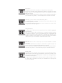
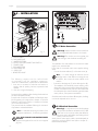
Prima della messa in funzione, leggere attentamente il manuale di istruzioni
Carefully read the following instruction booklet before starting up the machine.
Lesen Sie vor der Inbetriebnahme aufmerksam die Bedienungsanleitung.
Avant la mise en service, lire attentivement le manuel dÊinstructions.
Antes de la puesta en funcionamiento, hay que leer atentamente el manual de instrucciones
Attenzione! Togliere l’alimentazione elettrica prima di asportare le protezioni
Carefully turn off the electrical supply before removing the protections
Achtung! Schalten Sie vor dem Entfernen der Schutzabdeckungen die Stromzufuhr ab
Attention ! Débrancher l’alimentation électrique, avant d’enlever les protections.
¡Atención! Desconectar la alimentación eléctrica antes de extraer las protecciones
Attenzione! Superfici calde
Important ! Hot surfaces.
Achtung! Oberfläche heiß
Attention ! Surfaces chaudes.
¡Atención! Superficies calientes
Attenzione! Operazioni particolarmente importanti e/o pericolose
Important! Particularly important and/or delicate operations
Achtung! Besonders wichtige und / oder gefährliche Arbeitsgänge.
Attention ! Opérations particulièrement importantes et/ou dangereuses.
¡Atención! Operaciones particularmente importantes y/o peligrosas
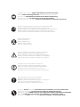
Importante! Interventi necessari al buon funzionamento.
Important ! Operations essential to guarantee efficient function
Wichtig! Für eine gute Funktionsweise erforderliche Maßnahmen.
Important ! Interventions nécessaires au bon fonctionnement.
¡Importante! Intervenciones necesarias para el buen funcionamiento.
Interventi che possono essere svolti a cura dell’utente
Operations which may be carried out by the user
Maßnahmen, die durch den Anwender vorgenommen werden können
Interventions pouvant être effectuées par l’utilisateur.
Intervenciones que pueden ser realizadas por el usuario
Interventi che devono essere svolti esclusivamente da un installatore o un tecnico autorizzato.
Interventions to be carried out exclusively by an installer or authorized technician.
Eingriffe, die nur von einem Installateur oder von einem autorisierten Techniker vorgenommen werden dürfen.
Interventions à effectuer uniquement par un installateur ou un technicien autorisé.
Intervenciones que tienen que ser efectuadas sólo por el instalador o el técnico Autorizado.

36
English
ITALIANO 8 - 35
ENGLISH 36 - 63
DEUTSCH 64 - 91
FRANÇAIS 92 - 119
ESPAÑOL 120 - 147

37
English
TABLE OF CONTENTS
TABLE OF CONTENTS. .........................................................................37
1- USE AND PRESERVATION OF THE
INSTRUCTION MANUAL
. .....................................................38
2- HOW TO USE THE MACHINE ........................38
3 - SAFETY WARNINGS
. .....................................39
4 - TECHNICAL FEATURES
. ..................................40
5 - INSTALLATION
. ..............................................41
5.1 Water connection
. .................................41
5.2 Electrical connection
. .............................41
6 - COMPONENTS DESCRIPTION
. ......................42
7 - INITIAL START UP OPERATION
. .....................43
7.0.1 OFF mode ( Model “D” ) ........................43
7.0.2 ON mode ( Mod. “D” ) ..........................43
7.0.3 ON mode ( Mod. “E” ) ..........................43
7.1 Pressure switch adjustment
. ......................44
7.2 Pressure pump calibration
. .......................44
7.3 Coffee filters supplied with the machine
. .....44
7.4 Spouts supplied with the machine ..............45
7.5 High raised group spouts supplied with the
machine ...............................................45
7.6
Long coffee nozzle supplied with the machine
..45
8 - OPERATION/USE AND USER
PROGRAMMING
. ...........................................45
8.1 Coffee dose programme
. .......................46
8.2 Tea dose programme
. .............................48
8.3 Coffee delivery. .....................................49
8.4 Continuous coffee dose
. ..........................49
8.5 Hot water delivery
. ................................50
8.6 Model “E” deliveries . .............................50
8.7 Timer programming ( Model “D” )
. .............51
8.8 Auto ON/OFF ( Model “D” ) ...................51
8.8.1 Rest day ...............................................52
8.9 Calculations
. ........................................52
SPECIAL FUNCTIONS
. ....................................52
9 - TECHNICAL PROGRAMMING MODEL „D‰
INTRODUCTION ............................................53
9.1 Language ...........................................53
9.2 Name
. ................................................53
9.3 Telephone Support
. ................................54
9.4 Keyboard Type ......................................54
9.5 Dose Programming
. ...............................54
9.6 Continuous button ..................................54
9.7 Tea/mixed Hot Water . ..........................54
9.8 Pre-infusion ..........................................54
9.8.1 Pre-infusion parameters ...........................54
9.9 Sensitivity
. .............................................55
9.10 Maintenance Cycles ...............................55
9.11 Temperature ..........................................55
9.12 Number of Units ....................................55
9.13 Units temperature ...................................55
9.14 PID type thermostat control .......................55
9.15 PID control ............................................56
9.16 Filling Time-Out ......................................56
9.17 Water Filters .........................................56
10 - TECHNICAL PROGRAMMING MODEL „E‰
INTRODUCTION ...........................................56
10.1 Language ............................................57
10.2 Tea/mixed Hot Water
. ..........................57
10.3 Sensitivity
. ............................................57
10.4 Maintenance Cycles ...............................57
10.5 Temperature
. .........................................57
10.6 Number of Units ....................................57
10.7 Units Temperature
. ................................58
10.8 PID type thermostat control ......................58
10.9 PID control ............................................58
10.10 Filling Time-Out ......................................58
11 - UNITS TEMPERATURES TECHNICAL
DISPLAY ........................................................58
11.1 MODEL “D” .........................................58
11.2 MODEL “E” . ........................................59
12 - ALARMS ........................................................59
12.1 Boiler level Time out (filling) ....................59
12.2 Volumetric Meters Alarm ( Model “D” )
. .....59
12.3 Filter alarm (Model “D”) ...........................59
12.4 Maintenance Alarm ................................60
12.5 Unit temperature Probe alarm ...................60
13 - TOTALS RESETTINGS
. ....................................60
13.1 Single doses totals resetting .....................60
14 - WATER SOFTENER REGENERATION
.. ............61
15 - MAINTENANCE AND USEFUL ADVICE
. ........62
16 - TROUBLESHOOTING
.. ....................................63
17 - MACHINE DISMANTLING
.. ...........................63

38
English
1 - USE AND PRESERVATION
OF THE MANUAL
This manual is intended for in-house use only and/or the
authorized service centres for GAGGIA professional ma-
chines.
The manual is addressed to the maintenance and installation
operators of the machine
The instruction manual aims to describe how to use the
machine the way the machine is designed to be used, the
machine’s technical features and to provide information on
how to use the machine correctly, and how to the clean,
control and operate the machine; in addition, the manual
provides important information about maintenance, any
residual risks and however how to carry out operations to
be performed with special care.
This manual is to be considered a part of the machine and
must be PRESERVED FOR FUTURE REFERENCE until the
machine is finally dismantled.
The instruction manual must always be available for consul-
tation and be preserved in a protected and dry place.
The user can request a new manual from the manufacturer or
from the local retailer if the manual is lost or damaged. The
request must include details of the machine model and the
serial number indicated on the identifying data plate.
This manual reflects the technical features at the date of
preparation; the manufacturer reserves the right to upgrade
the production and the subsequent manuals without being
under an obligation to also update previous versions.
The manufacturer accepts no liability in the following ca-
ses:
- improper or incorrect use of the coffee machine
- use that does not comply with the information expressly
specified in this publication
- serious shortcomings in the foreseen and recommended
maintenance operations
- changes made to the machine or any unauthorised
operation
- using non-genuine spare parts or parts not specific to the
model
- total or even partial non-compliance with the instructions
- Exceptional events.
2 - INTENDED USE OF THE
MACHINE
The machine must be operated by a single operator.
The designated operator must have read and fully understood
the instructions contained in this manual in order to operate
the machine correctly.
This machine is designed to be used for the professional
preparation of espresso coffee with coffee blends, to use
and deliver water and/or steam.
The machine’s components are manufactured using non-toxic
and long-lasting materials and are readily accessible for
cleaning and maintenance operations.
This machine is designed exclusively for indoor use.
Room temperature for the machine’s correct operation:
5°C ÷ 25°C.

39
English
3 - SAFETY WARNINGS
Only adults who have carefully read and fully understood
this manual and all the safety information contained in the
manual are permitted to use the machine.
The appliance is not to be used by persons (including chil-
dren) with reduced physical, mental or sensory abilities or
with limited experience and/or expertise, unless they are
supervised by a person responsible for their safety, or they
are instructed by this person on how to properly use the
appliance.
- Children must be supervised to ensure they do not play
with the appliance.
- This appliance is to be used for household applications or
in similar areas like:
. for staff only cooking areas in shops, offices and other
professional environments;
. farms;
. for clients use in hotels, motels and other residential type
areas;
. environments like bed and breakfasts.
The user is liable towards third parties in the working
area.
The installer, the user and the maintenance technician are
required to inform the manufacturer regarding any faults
or deterioration that may compromise the system’s original
level of safety.
The installer is required to verify the correct environmental
conditions, and to ensure the safety and hygiene of the
operator and of the users.
Do not install the appliance in a location where water jets
may be used.
The appliance must only be installed in places where it can
be used and maintained only by qualified staff.
The installation operation must be performed exclusively by
authorised and qualified personnel.
The machine is to be used only when the lighting conditions
are suitable.
Worn or damaged parts must be replaced promptly and
using genuine spare parts for safety reasons.
Check regularly that the power supply cable is undamaged.
Under no circumstance shall the electric power cable that
may have been damaged be repaired with insulating tape
or using terminals.
If the power supply cable is damaged, it must be replaced
by the manufacturer or by its technical assistance dept. or
anyway by a similarly qualified person so to prevent any
possible hazard.
Do not expose the machine to weathering (sun, rain, etc.).
Prolonged inactivity (machine not operating) at a tempera-
ture of less than 0°C (zero degrees centigrade), can cause
serious damage or failure of the pipes and of the boiler;
drain the hydraulic circuit completely before every extended
period of inactivity.
Removing the protection and /or safety devices foreseen
on the machine is strictly prohibited.
The packing components are to be delivered to the spe-
cific waste disposal centres and under no circumstance
left unguarded or within the reach of children, animals or
unauthorised persons.
The manufacturer declines all liability for damage to property,
injury to persons or animals caused by any operations on
the machine performed by persons who are unqualified or
unauthorised to carry out such tasks.
The warranty terms and conditions will no longer apply if
any unauthorised repair operations are performed on the
machine or non-genuine spare parts are used and therefore
the manufacturer reserves the right not to acknowledge the
validity of the warranty.
The user is required to comply with the safety provisions
applicable in the country of installation, in addition to com-
mon sense rules and to ensure that the periodic maintenance
operations are performed correctly.
Do not clean the machine’s internal parts when the machine is
energised or with the plug in the power socket and however
do not use water sprays or detergents.
The user must not touch the machine if his hands or feet are
wet or damp, neither must be use the machine in bare feet.
Although the machine is earthed it is advisable to use wo-
oden platforms or a cut-out box complying with local laws
in order to prevent the risk of electrocution.
Do not touch the coffee spouts and the hot water and steam
nozzles with your hands or any other parts of the body as
the liquids or steam issuing from them are very hot and may
cause burns.
Avoid operating the machine without water.
Clogging may cause the generation of sudden liquid or ste-
am jets with serious consequences. Therefore keep the water
as clean as possible using filters and water softeners.
The cups and small coffee cups must be thoroughly dried
before placed on the relative surface.

40
English
B
L
H
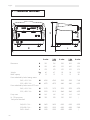
4 - TECHNICAL FEATURES
fig. 1
2
units
2 GA
units
3
units
3 GA
units
4
units
Dimensions
B
765 765 985 985 1205
H
535 620 535 620 535
L
570 570 570 570 570
Weight
kg
60 67 80 86 100
Boiler capacity
l
13 13 21 21 28
Power absorbed by boiler heating resistor
240 / 415 V 3 N ~
W
4760 4760 5950 5950 7140
230 / 400 V 3 N ~
W
4370 4370 5465 5465 6555
Power absorbed by boiler resistor ECO max.
240 / 415 V 3 N ~
W
3170 3170 3970 3970 4750
230 / 400 V 3 N ~
W
2910 2910 3640 3640 4370
Pump motor
W
165 165 165 165 165
UL - CSA pump motor
W
330 330 330 330 /
Total power absorbed
240/415 V 3 N ~
W
5400 5400 6760 6760 8050
230/400 V 3 N ~
W
5000 5000 6000 6000 7400
240 V 60Hz 2 ~
W
5580 5580 6900 6900 /

41
English
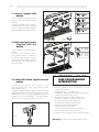
5 - INSTALLATION
A - WATER MAINS
B - DISCHARGE LINE
C - WATER SOFTENER
D - PROTECTION DISCONNECTING SWITCH
E - POWER CABLE
F - DISCHARGE TRAY
G - DISCHARGE PIPE
H - SUPPLY PIPE
I - BOILER FEED VALVE
D
C
A
B
E
F
I
H
G
G
H
fig. 2
5.2 Electrical Connection
Warning! It is important to ensure that the voltage
corresponds to the features indicated on the EC data
plate and on the connection data plate affixed to
the power supply cable before proceeding with the
electric power connection.
VVerify that the mains supply cable is sized adequately to
support the machine’s electric load (refer to chapter 4 –
technical features table).
The following aspects must be verified befo-
re proceeding with the installation operations:
- there are no obvious dents, impact marks or deformations
1 there are no wet areas or marks that can lead to su-
specting that the packing has been exposed to bad
weather
2 there are no signs of tampering.
Proceed with the installation after checking that the machine
has been transported correctly.
Ensure that the in machine is installed on a flat surface capa-
ble of supporting the weight (refer to chapter 4 “Technical
Features”) and ensure that there is a clearance of at least
30 cm around the machine.
Then proceed with the installation following the succession
of operations as described below.
N.B. It is advisable that the higher surface of the
equipment is at least at 1,5 m from the ground level.
N.B.: ONLY FOR NSF HIGH RAISED GROUPS
VERSION
Replace the appliance feet with the ones supplied
(fig. 2a).
Warning!
Water and waste connections shall com-
ply with applicable federal states or local codes.
Warning! The machine must be supplied with
water having a water hardness exceeding 8°F.
The installation of a water softener on the machine’s water
supply line is recommended.
Ensure that the connected water mains supplies drinking
water.
- Connect the water softener (C) to the water mains (A).
N.B. p. run water through the machine until the
discharge water is clear before connecting the wa-
ter softener, then connect the water softener to the
machine.
- Connect the discharge tray (F) to the discharge line (B):
- The installation of a balanced pressure reducing valve
designed for high-pressure (a device designed so that any
increase in the water mains pressure is not transferred to
the outlet pressure) is recommended as regards the water
mains pressure, if the pressure exceeds bar.
Should the machine be moved to a different place, the fitting
unit must be replaced with a new one.
5.1 Water Connection
fig. 2a

42
English
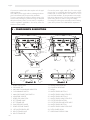
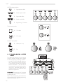
6 - COMPONENTS DESCRIPTION
1 BOILER FILLING VALVE
2 DISCHARGE PIPE
3 MACHINE ON WARNING INDICATOR
4 CUP WARMING SWITCH
5 MAIN DISCONNECTING SWITCH
6 ADJUSTABLE SUPPORT
7 BOILER LEVEL INDICATOR
8 LEFT STEAMER VALVE
9 LEFT STEAMER PIPE
10 PUMP PRESSURE GAUGE
11 BOILER PRESSURE GAUGE
12 HOT WATER DELIVERY PIPE
13 RIGHT STEAMER VALVE
14 RIGHT STEAMER PIPE
15 DELIVERY INDICATOR LED
16 CONTROLS KEYBOARD
17 DISPLAY
18 WATER DELIVERY BUTTON 1
19 WATER DELIVERY INDICATOR LED 1
20 WATER DELIVERY BUTTON 2
21 WATER DELIVERY INDICATOR LED 2
22 COFFEE DELIVERY BUTTON
23 COFFEE DELIVERY INDICATOR LIGHT
24 WATER DELIVERY BUTTON
25 WATER DELIVERY INDICATOR LIGHT
26 FILTER HOLDER BOWL
27 ADDITIONAL ESPRESSO GRILL
Connect to an earthed socket that complies with the appli-
cable regulations.
Verify that the power supply cable is undamaged and com-
plies with National and European safety standards.
The user is responsible for supplying electric power to the
machine and protecting the power line using an adequate
safety disconnecting switch (cut out switch) in compliance
with the regulations applicable in the country where the
machine is to be installed.
Connect the power supply cable (I) to the mains supply
using a plug, or a multi-pole disconnecting switch must be
foreseen with a contacts distance of at least 3 mm in the
case of a fixed installation, (D) to separate the mains supply.
Refer to the diagram shown on the box containing the main
disconnecting switch in order to change the voltage.
Connecting the yellow/green coloured wire to the earthing
system of the premises is a COMPULSORY requirement.
fig. 3
12
6
3
4
5
7
8
9
10
11
12
13
14
18
19
15
21
20
17
16
17
22
23
25
23
22
24
Model. D
Model. E
26
8
9
7
6
2
1
13
14
11
10
12
26
27

43
English
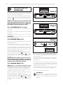
Proceed with the initial start up operation of the machine after
the water and electrical connections have been completed.
Open the water mains valve (A) (fig. 2).
Switch on the protection disconnecting switch (D) (fig. 2).
Switch the machine’s main power switch (5) to the position
marked by: . The machine ON indicator will be ener-
gised (3).
NOTE: the machine will return to the OFF or ON
mode that existed before the mains supply was
disconnected when electric power is supplied to
the machine via the main power switch.
IMPORTANT:
Do not press the hot water delivery button or switch
before the correct operating pressure has been
reached 1.1 atm, indicated by the boiler pressure
gauge (11).
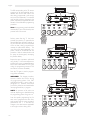
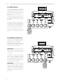
7 - INITIAL START UP
OPERATION
The self-levelling mechanism will be activated until the
water reaches the normal level inside the boiler. (7).
The machine changes to ON mode after the correct levels
have been established; all the leds will be energised in this
mode and the display will show the current time, in hours
and minutes and the name (fig. 4.01).
Once loading has been completed switch the main power
switch (5) to the position marked: to operate in normal
power conditions or to the position marked: o operate
at maximum power, the heating resistors are energised in
this mode.
IMPORTANT: if the heating resistors are activa-
ted immediately when the boiler is empty the
resistors only change to heated mode after the
water has been completely charged.
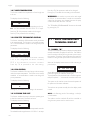
7.0.1 OFF MODE (Model “D” only)
The machine will be inactive but is energised when in the
OFF mode.
All the functions are disabled except the technical parameters
programmes.
The display will indicate the current time in hours and mi-
nutes. (fig. 4).
IMPORTANT: press key T5 with key T3 of unit 1 to change
from ON mode to OFF mode.
7.0.2 ON MODE (Model “D”)
Press key T3 (fig. 4.01) to change from OFF mode to ON
mode (Model “D” only).
hh : mm
OFF
fig. 4
Model D
7.0.3 ON MODE (Model “E”)
NOTE: Model “E” is not designed with the OFF mode,
consequently the machine will be immediately in the ON
mode when the main power switch is switched to ON.
The self-levelling mechanism will be activated until the water
reaches the normal level inside the boiler. (7).
Once the correct levels have been reached the display will
show the information as indicated in fig. 4.02.
Wait until the machine has reached the operating pressure
1.1 – 1.3 atm. by checking the boiler pressure on the
pressure gauge (11).
If the machine does not stabilise at the values indicated then
the pressure switch will require calibration as specified in
paragraph 7.2.
Then check the pressure on the pump pressure gauge (10)
by operating one unit with the filter holder in position filled
with ground, dosed and pressed coffee to obtain the real
operating pressure of 8/9 atm.
If the pump pressure needs to be re-calibrated then this ope-
ration must be performed as specified in paragraph 7.3.
The machine is now ready to be used.
Select function
Deco Manual
fig. 4.02
Model E
hh : mm
DECO
fig. 4.01
Model D
Once loading has been completed switch the main power
switch (5) to the position marked: to operate in normal
power conditions or to the position marked: to operate
at maximum power, the heating resistors are energised in
this mode.

44
English
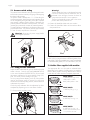
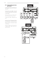
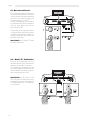
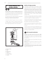
7.1 Pressure switch setting
The pressure switch indicated in the figure is designed to main-
tain the boiler pressure constant by energising or de-energising
the electric heating resistor.
This pressure switch is already set to 1.1÷1.3 bar during the
machine testing stage, but the pressure switch operating range
can be changed by turning the setting screw (U) if a specific
case requires a different working pressure: decreasing the
pressure produces a decrease in the temperature, vice versa,
increasing the pressure also increase the water temperature.
The setting direction is indicated in the figure and also on the
pressure switch itself. The pressure varies by approximately
0.1 atm. for every complete turn of the screw.
Warning! Disconnect the power supply before
performing this operation.
fig. 5
7.2 Pump pressure calibration
Position the filter holder filled with ground, dosed and pressed
coffee in the unit. Press the unit switch (MANUAL DECO)
or the control keyboard (DOSED DECO) (16) and read
the pressure indicated on the pump pressure gauge (10).
N.B. The correct pressure reading is 8/9 atm.
Turn the pump pressure adjusting screw (Z) if the pressure
read on the pressure gauge is incorrect, turn the screw
clockwise to increase the pump pressure, and anticlockwise
to decrease the pressure.
Check the pump calibration after the adjustment has been
completed by dispensing one or more doses of coffee.
Z = Pump pressure regulating screw
Warning!
The filter holder bowl may not be aligned (perpendi-
cular to the machine) when the machine is new, as
indicated in the next figure, however this does not
compromise the machine’s correct operation.
The bowl will gradually position itself in the correct
position after a short period of use.
A = Position of closed filter holder with new machine
B = Position of closed filter holder with the machine after a
short period of use.
fig. 6
fig. 7
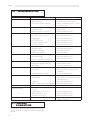
7.3 Coffee filters supplied with machine
The appropriate filter is to be used as indicated below
depending on the quantity of coffee ground, to avoid the
leftover coffee powder remaining attached to the delivery
nozzle after the coffee has been completely dispensed.
20 mm
24,5 mm
24,5 mm
21 mm
NF08/002/B
1 coffee cup of 5.5 gr ÷ 6.6
coffee pod for 1 coffee
Barley coffee pod for 1 dose
NF08/004/B
1 coffee cup of 6 gr ÷ 7 gr
NF08/005/B
2 coffee cups of 12 gr ÷ 14
NF08/009/B
2 coffee cups of 12 gr ÷ 14
The filter can be identified by a letter
“C” impressed on the inside.
A
B
NOTE: Smaller thickness under-bowl gaskets (8.1 mm code
NG01/005), or larger thickness under-bowl gaskets (9 mm
code NG01/002) are available as an option compared to
the standard fitted gasket (8.5 mm code NG01/001/B).

45
English
The following operations can be monitored by using the
programming software:
- management of 2 – 3 - 4 coffee units
- controlling four different coffee doses for each unit (Model “D”).
- controlling the tea doses (hot water)
- simultaneous operation of coffee and tea units
- volumetric control of the coffee doses (Model “D”)
- timer control of the tea doses (Model ”D”)
- simulated doses programming (Model D”)
- filling level control and management
- system supervision via the alarms
- continuous, time out delivery and other functions
- series connection with accounting devices
- back-lit LCD 16 x 2 display to view the functional status.
Warning! The display shows the last selection made.
8 - OPERATION / USE AND
USER PROGRAMMING
INTRODUCTION
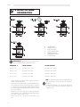
7.4 Spouts supplied with
machine.
4 types of spouts are supplied with the
machine to have single or double coffee
brewings.
The figure on the side shows the various
possible distances from the cup holder
grill (H) in relation to the different types of
spouts assembled on the filter holder.
7.5 High raised group spouts
s u p p l i e d w i t h t h e
machine.
2 types of spouts are supplied with the
machine.
The figure on the side shows the va-
rious possible distances in relation to
the different types of spouts and cup
holder grills used (cup holder grill H for
espresso coffee - cup holder grill H1 for
American coffee).
fig. 8
7.6 Long coffee nozzle supplied with the
machine
The machine is equipped with a gigleur (1 per
unit) with a Ø0.6mm size through passage (Code
WGA26G0074/01).
2 gigleurs are supplied together with the machine (complete
with gasket) providing a Ø0.8mm through passage (Code
WGA26G0073/01) if a higher coffee delivery speed is
required in the case of weak coffees. The gigleur is positio-
ned in the heat exchanger feed fitting (1 per unit).
93
106
106
96
Dpe/!22124965
I >!!!:4!nn
I2 >!289!nn
Dpe/!22124:26
I >!!!:7!nn
I2 >!292!nn

46
English
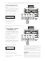
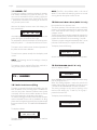
8.1 PROGRAMMING COFFEE
DOSES
The coffee dose quantities can be changed
(using the volumetric control) and the settings
can be memorised by proceeding as follows:
- press key T5 (on the keyboard referring to
unit 1) and continue to press for more than
5 seconds and verify that all the keyboard
leds are illuminated. In this case all units
are programmed, (using the keyboard refer-
ring to unit 1), whereas by pressing key T5
of another unit only the unit that has been
selected is programmed.
WARNING! The settings on unit 1 (using the
first keyboard), are automatically copied also
on all the other units.
Press the key corresponding to the dose to be
programmed within 30 seconds (programming
time out), (for example: key T1).
T5
Programming
Selection in 30secs.
T1 - Single espresso coffee
T2 - Double espresso coffee
T3 - Single weak coffee
T4 - Double weak coffee
T5 - Programming / Continuous
COFFEE keyboard symbols:
TEA keyboard symbols:
T6 - 1 Tea dose
T7 - 2 Tea doses
Model “E” keys symbols:
T8 - Coffee (Units 1÷4)
T7 - Tea

47
English
T1
Espresso
Programming
Delivery starts after key T1 has been
pressed, then press key T1 again after the
desired coffee dose has been reached, or
any one of the other keys on the keyboard
of the unit that is being programmed to
interrupt the coffee dose delivery. The
new value of the dose expressed in im-
pulses is stored on the EPROM with this
procedure. Both the solenoid valve and
the pump are de-energised, interrupting
the product delivery.
Repeat the same operations performed
using the key T1 in the same sequence to
proceed with a new programmed setting
for the other coffee doses T2-T3-T4, (pro-
viding the programming time-out of 30
seconds has not been exceeded).
Press key T5 again to exit the program-
ming phase immediately.
WARNING! The dosage procedure,
however enables this function during
the programming phase if the “PRE-
INFUSION” function is active (refer to
paragraph 7.5). Therefore, wait until the
pre-infusion phase has terminated before
interrupting the delivery in progress.
NOTE: the operation of the other units
and tea dispensing are disabled during
the programming phase of a given unit.
Press the specific programming key for
each unit to programme the other units,
and proceed with the same operations
performed on unit 1. In this case any
changes in the dose become applicable
to the single unit that is being used.
T5
Programming
Selection in 30secs.
T1
Espresso
Gr. 2 Programming
The LED corresponding to key T5 remains
energised on all the keyboards and in
addition also the LED that refers to the
dose being programmed is also energi-
sed (on all the keyboards). The solenoid
valve and the pump are energised in this
phase, and remain energised for the entire
duration of the coffee dose programming
procedure.
Note: the programming mode is disabled
automatically if none of the dose keys are
pressed within 30 seconds.

48
English
8.2 Programming tea doses
(hot water)
The timed quantities for the tea doses can
be changed by following the sequence
described:
Press key T5 on the coffee 1 unit and
continue pressing for more than 5 seconds
and verify that all the leds on the keyboard
are illuminated.
Press key T6 Tea 1 or key T7 Tea 2 within
30 seconds (programming time-out).).
The dose of tea water is delivered in this
way.
Press key T6 or key T7 again after the de-
sired dose has been obtained to interrupt
the water delivery. In this way the new
delivery time for the Tea water is stored
in the memory.
Press key T5 again to switch the machine
to standby mode in order to exit the pro-
gramming phase.
T5
Programming
Selection in 30 secs.
T6
T7
Tea
Programming

49
English
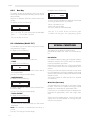
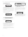
8.3 Coffee delivery
The corresponding delivery solenoid val-
ves are energised for the time necessary
to distribute the quantity of product pro-
grammed previously (volumetric control)
by pressing the corresponding key: T1-
T2-T3 or T4.
The LED corresponding to the dose key of
the unit selected remains ON all the time
the coffee is delivered while the other Leds
will be OFF.
Interrupting the delivery in progress before
the quantity of product programmed it
reached is possible by pressing any one
of the dose keys on the keyboard of the
unit being used to deliver the product.
Coffee can be distributed simultaneously
from all the units installed on the machi-
ne.
8.4 Continuous coffee dose
Press key T5 on the keyboard correspon-
ding to the unit to be used to obtain con-
tinuous delivery of the coffee dose.
The LED corresponding to key T5 remains
ON all the time the coffee is delivered
while the other Leds will be off.
IMPORTANT! Avoid pressing the button
for more than 5 seconds, because the
machine will switch to programming mode
in this case
The coffee will continue to be delivered
until the dose is stopped by pressing
key T5, or until the maximum quantity of
product obtainable using the volumetric
control is reached (6,000 impulses) or until
the delivery time-out is reached.
IMPORTANT! The START mode referred
to the “Continuous” cycle is obtained
when key T5 is released (within 5 se-
conds) and not when this key is pressed.
Whereas, the STOP mode, if applicable,
is obtained by pressing the same key a
second time.
T1
T5
Continuous

50
English
8.6 Model “E” distributions
Press key T8 corresponding to the unit
intended to be used or key T9 to obtain the
distribution of the coffee or tea dose.
The indicator light corresponding to the
key will be energised and will remain ON
for all the duration of the delivery while the
other indicator lights will be OFF.
IMPORTANT! key T8 and key T9 are
ON - OFF buttons, therefore press once to
activate delivery and press a second time
to interrupt the delivery. The distribution
is not volumetric.
Contiuno / Tea
T8
T9
8.5 Hot water deliveries
PThe corresponding delivery solenoid val-
ves are activated for the time necessary to
reach the quantity of product programmed
previously (timer control) by pressing the
corresponding key T6 or key T7.
The LED corresponding to the TEA dose
key selected remains ON for the duration
of the hot water delivery time, while the
other Led will be OFF.
The possibility of interrupting the delivery
in progress before reaching the quantity
of product programmed is foreseen by
pressing the dose key used to deliver the
product a second time.
IMPORTANT! key T6 and key T7 cannot
be used simultaneously.
T6
T7
La pagina si sta caricando...
La pagina si sta caricando...
La pagina si sta caricando...
La pagina si sta caricando...
La pagina si sta caricando...
La pagina si sta caricando...
La pagina si sta caricando...
La pagina si sta caricando...
La pagina si sta caricando...
La pagina si sta caricando...
La pagina si sta caricando...
La pagina si sta caricando...
La pagina si sta caricando...
-
 1
1
-
 2
2
-
 3
3
-
 4
4
-
 5
5
-
 6
6
-
 7
7
-
 8
8
-
 9
9
-
 10
10
-
 11
11
-
 12
12
-
 13
13
-
 14
14
-
 15
15
-
 16
16
-
 17
17
-
 18
18
-
 19
19
-
 20
20
-
 21
21
-
 22
22
-
 23
23
-
 24
24
-
 25
25
-
 26
26
-
 27
27
-
 28
28
-
 29
29
-
 30
30
-
 31
31
-
 32
32
-
 33
33


in altre lingue
- English: Gaggia DECO
Documenti correlati
Altri documenti
-
Hendi 274149 Manuale utente
-
-
ELEKTRA Professional espresso coffee machines Manuale utente
-
Rancilio CLASSE 10 Use And Maintenance
-
-
-
-
-
-
D-Link DPE-101GI Quick Installation Manual