IMG STAGELINE TXS-606LT Manuale utente
- Categoria
- Microfoni
- Tipo
- Manuale utente

ELECTRONICS FOR SPECIALISTS ELECTRONICS FOR SPECIALISTS ELECTRONICS FOR SPECIALISTS ELECTRONICS FOR SPECIALISTS
TXS-606LT
Bestell-Nr. • Order No. 0253550
Taschensender
mit Krawattenmikrofon
Pocket Transmitter
with Tie Clip Microphone
BEDIENUNGSANLEITUNG
INSTRUCTION MANUAL
MODE D’EMPLOI
ISTRUZIONI PER L’USO
MANUAL DE INSTRUCCIONES
INSTRUKCJA OBSŁUGI
672,000 – 691,975 MHz


3
IR
CHANNEL
BATT
GROUP
CHANNEL
BATT
GROUP
10
1
2
3
4
5
6
7
8
9
11 12
➀ ➁
➂

4
Deutsch
English
English Page
Français
Français Page
Italiano
Italiano Pagina
Español
Español Página
Nederlands
Nederlands Pagina
Polski
Polski Strona
Deutsch
Deutsch Seite
Taschensender mit
Krawattenmikrofon
Diese Bedienungsanleitung richtet sich an Benutzer ohne
besondere Fachkenntnisse. Bitte lesen Sie die Anleitung
vor dem Betrieb gründlich durch und heben Sie sie für
ein späteres Nachlesen auf.
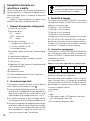
Auf der ausklappbaren Seite 3 finden Sie alle beschrie-
benen Bedienelemente.
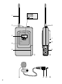
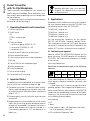
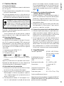
1 Übersicht der Bedienelemente und
Anschlüsse
1 Sendeantenne
2 Ein- und Ausschalter
OFF = Aus
STDBY = Ton stumm geschaltet
ON = Ein
3 Display zur Anzeige:
1. der Kanalgruppe (GROUP 00 – 07)
2. des Kanals (CHANNEL 00 – 99)
3. des Batteriezustands
4 Sensor für die Infrarotsignale zur Kanaleinstellung
5 Batteriefachdeckel
6 Anschlussbuchse für das Krawattenmikrofon
7 Gürtelklemme
8
Regler GAIN zum Einstellen der Verstärkung des
Mikrofonsignals
9 Batteriefach
10 Krawattenmikrofon
11 Überwurfmutter zum Sichern des Steckers
12 Anschlussstecker (3,5-mm-Klinke)
2 Wichtige Hinweise
Der Taschensender entspricht allen relevanten Richtlinien
der EU und trägt deshalb das -Zeichen.
•
Der Taschensender ist nur für die Verwendung im In-
nenbereich geeignet. Schützen Sie ihn vor Tropf- und
Spritzwasser, hoher Luftfeuchtigkeit und Hitze (zuläs-
siger Einsatztemperaturbereich 0 – 40 °C).
•
Verwenden Sie zum Reinigen nur ein trockenes, weiches
Tuch, niemals Wasser oder Chemikalien.
•
Wird der Taschensender zweckentfremdet, falsch be-
dient oder nicht fachgerecht repariert, kann keine Haf-
tung für daraus resultierende Sach- oder Personen-
schäden und keine Garantie für den Taschensender
übernommen werden.
Soll der Taschensender endgültig aus dem
Betrieb genommen werden, übergeben Sie ihn
zur umweltgerechten Entsorgung einem ört-
lichen Recyclingbetrieb.
3 Einsatzmöglichkeiten
Der Taschensender TXS-606LT bildet mit folgenden
Empfängern von IMG STAGELINE ein drahtloses Audio-
Übertragungssystem:
TXS-606 mit 1 Empfangseinheit
TXS-626 mit 2 Empfangseinheiten
TXS-646 mit 4 Empfangseinheiten
TXS-686 mit 8 Empfangseinheiten
Die Übertragungsfrequenz wird am Empfänger eingestellt
(672,000 – 691,975 MHz, Frequenzraster 25 kHz). An-
schließend wird komfortabel nur durch einen Knopfdruck
der Taschensender über ein Infrarotsignal auf den am
Empfänger gewählten Kanal abgestimmt (ACT-Funktion
= Automatic Channel Targeting).
3.1 Konformität und Zulassung
Hiermit erklärt MONACOR INTERNATIONAL, dass der
Taschensender TXS-606LT der Richtlinie 2014 / 53 / EU
entspricht. Die EU-Konformitätserklärung ist im Internet
verfügbar:
www.img-stageline.de
Es bestehen Beschränkungen oder Anforderungen
in folgenden Ländern:
CZ DE EL FI FR
IT LT MT PL
Der Taschensender muss im Gebiet der Bundes republik
Deutschland eine Frequenzzuteilung (kostenpflichtig) er-
halten. Die Formulare und Hinweise zur Anmeldung fin-
den Sie im Internet auf der Seite der Bundesnetzagentur:
www.bundesnetzagentur.de
In anderen Ländern muss eine entsprechende Genehmi-
gung beantragt werden. Informieren Sie sich bitte vor der
Inbetriebnahme des Taschensenders außerhalb Deutsch-
lands bei der MONACOR-Niederlassung oder der entspre-
chenden Behörde des Landes. Links zu den nationalen
Behörden finden Sie über die folgende Internetadresse:
www.cept.org
t ECC
t Topics
t Other spectrum topics: SRD Regulations and indica-
tive list of equipment sub-classes
t EFIS and National Frequency Tables

5
Deutsch
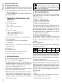
4 Inbetriebnahme
4.1 Batterien einsetzen
Für den Betrieb des Taschensenders werden zwei
1,5-V-Batterien der Größe Mignon (AA) benötigt.
•
Setzen Sie nur Batterien oder Akkus des gleichen Typs
ein und tauschen Sie sie immer komplett aus.
•
Nehmen Sie bei längeren Nichtgebrauch die Batterien
heraus. So bleibt der Sender bei einem eventuellen
Auslaufen der Batterien unbeschädigt.
Verbrauchte Batterien und defekte Akkus dür
-
fen nicht in den Hausmüll geworfen werden.
Geben Sie sie zur umweltgerechten Entsor-
gung nur in den Sondermüll (z. B. Sammelbe-
hälter im Einzelhandel).
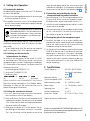
Zum Öffnen des Batteriefachs (9) auf den Pfeil des Bat-
teriefachdeckels (5) drücken und dabei den Deckel nach
unten schieben.
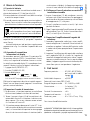
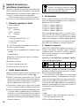
Die Batterien mit den Plus- und Minuspolen, wie in der
Abb. 2 dargestellt, einsetzen und den Batteriefachdeckel
wieder aufsetzen.
4.2 Sender einschalten / Informationen im Display
Zum Einschalten den Schalter (2) in die Position ON
schieben. (In der Mittelposition STDBY arbeitet zwar der
Sender, jedoch ist das Mikrofonsignal stumm geschaltet.)
Die Hintergrundbeleuchtung des Displays (3) leuchtet
für einige Sekunden. Das Display zeigt folgende Infor-
mationen an:
1. die Kanalgruppe (GROUP 00 – 07)
2. den Kanal (CHANNEL 00 – 99)
3. den Batteriezustand
BATT
■
■
■
■
■
BATT
■
■
■
BATT
voll halb voll leer
Blinkt die Anzeige BATT, die Batterien austauschen.
Die in den folgenden Kapiteln beschriebenen Einstellun-
gen vornehmen. Nach dem Betrieb nicht vergessen, den
Sender auszuschalten, damit die Batterien nicht entladen
werden.
4.3 Übertragungskanal einstellen
1) Zuerst einen freien Übertragungskanal am Empfänger
einstellen (siehe Bedienungsanleitung des Empfängers).
2)
Den Infrarotsensor (4) des Senders in Richtung des
IR-Fensters am Empfänger halten. Der Abstand darf
nicht mehr als 1,5 m betragen und es muss Sichtver-
bindung zwischen Sensor und IR-Fenster bestehen.
3) Am Empfänger die Taste ACT kurz drücken. Die Dis-
play-Hintergrundbeleuchtung des Taschensenders
leuchtet auf und der Sender ist damit auf die gleiche
Kanalgruppe und den gleichen Kanal wie der Emp-
fänger eingestellt (siehe Anzeige im Display). Die den
Kanälen zugehörigen Frequenzen sind in der Tabelle
auf der Seite 16
angegeben.
4.4 Krawattenmikrofon und Taschensender
anschließen und befestigen
1) Den Stecker (12) des Krawattenmikrofons in die Klin-
kenbuchse (6) des Senders stecken. Um den Stecker
vor einem versehentlichen Herausziehen zu sichern,
die Überwurfmutter (11) auf die Buchse schrauben.
2) Das Krawattenmikrofon an der Kleidung befestigen,
möglichst nahe am Mund.
3)
Nach dem Einstellen der Mikrofonsignalverstärkung
(Kap. 4.5) den Sender mit der Klemme (7) an der Klei-
dung befestigen (z. B. am Gürtel oder am Hosenbund).
4.5 Verstärkung des Mikrofonsignals einstellen
1) Das am Empfänger angeschlossene Audiogerät (z. B.
Mischpult, Verstärker) einschalten. In das Mikrofon
sprechen / singen und die Lautstärke der Audioanlage
so einstellen, dass die nachfolgende Einstellung gut
zu hören ist.
2) Die Verstärkung des Mikrofonsignals mit dem Regler
GAIN (8) auf der Rückseite einstellen: Ist das Mikro-
fonsignal zu laut und verzerrt, den Regler mit einem
kleinen Schraubendreher zurückdrehen. Bei einem zu
leisen Signal ergibt sich dagegen ein schlechter Rausch-
abstand; den Regler dann entsprechend aufdrehen.
5 Technische Daten
Trägerfrequenz: . . . . . . . . . . . 672,000 – 691,975 MHz
Kanäle siehe Seite 16
Frequenzstabilität:
. . . . . . . . . ±0,005 %
Sendeleistung (EIRP): . . . . . . . 10 mW
Audiofrequenzbereich: . . . . . 30 – 18 000 Hz, ±3 dB
Stromversorgung: . . . . . . . . . 2 × 1,5-V-Batterie,
Größe Mignon (AA)
Betriebsdauer:
. . . . . . . . . . . . > 8 h
Einsatztemperatur: . . . . . . . . 0 – 40 °C
Abmessungen, Gewicht: . . . . 61 × 106 × 27 mm, 125 g
Änderungen vorbehalten.
Diese Bedienungsanleitung ist urheberrechtlich für MONACOR
®
INTERNATIONAL GmbH & Co. KG geschützt. Eine Reproduktion für
eigene kommerzielle Zwecke – auch auszugsweise – ist untersagt.

6
English
Deutsch
Deutsch Seite
Français
Français Page
Italiano
Italiano Pagina
Español
Español Página
Nederlands
Nederlands Pagina
Polski
Polski Strona
Pocket Transmitter
with Tie Clip Microphone
These instructions are intended for users without any
specific technical knowledge. Please read these instruc-
tions carefully prior to operating the unit and keep them
for later reference.
All operating elements and connections described can
be found on the fold-out page 3.
1 Operating Elements and Connections
1 Transmitting antenna
2 On / off switch
OFF
STDBY = sound muted
ON
3 Display to indicate
1. the channel group (GROUP 00 – 07)
2. the channel (CHANNEL 00 – 99)
3. the battery status
4 Sensor for the IR signals to set the channel
5 Battery compartment cover
6 3.5 mm jack to connect the tie clip microphone
7 Belt clip
8 Control GAIN for the microphone signal
9 Battery compartment
10 Tie clip microphone
11 Nut to secure the plug
12 Connector plug (3.5 mm plug)
2 Important Notes
The pocket transmitter corresponds to all relevant direc-
tives of the EU and is therefore marked with .
•
The pocket transmitter is suitable for indoor use only.
Protect it against dripping water and splash water, high
air humidity and heat (admissible ambient temperature
range 0 – 40 °C).
•
For cleaning only use a dry, soft cloth; never use water
or chemicals.
•
No guarantee claims for the pocket transmitter and no
liability for any resulting personal damage or material
damage will be accepted if the pocket transmitter is
used for other purposes than originally intended, if it
is not correctly operated, or if it is not repaired in an
expert way.
If the pocket transmitter is to be put out of
operation definitively, take it to a local recy-
cling plant for a disposal which is not harmful
to the environment.
3 Applications
To provide a wireless audio transmission system, combine
the multi-frequency pocket transmitter TXS-606LT with
the following receivers from IMG STAGELINE:
TXS-606 with 1 receiver unit
TXS-626 with 2 receiver units
TXS-646 with 4 receiver units
TXS-686 with 8 receiver units
Set the transmission frequency on the receiver
(672.000 – 691.975 MHz, frequency spacing 25 kHz).
Then simply press a button and, via IR signal, the pocket
transmitter is matched to the channel selected on the
receiver (ACT function = automatic channel targeting).
3.1 Conformity and approval
Herewith, MONACOR INTERNATIONAL declare that the
pocket transmitter TXS-606LT complies with the directive
2014 / 53 / EU
. The EU declaration of conformity is available
on the Internet:
www.img-stageline.com
Restrictions or requirements apply in the following
countries:
CZ DE EL FI FR
IT LT MT PL
In the Federal Republic of Germany, the pocket trans-
mitter requires a frequency assignment (for which a fee
is charged).
In other countries, it is necessary to apply for a corre-
sponding approval. Prior to operating the pocket trans-
mitter outside Germany, please contact the MONACOR
subsidiary or the corresponding authorities of the respec-
tive country. Links to the national authorities can be found
via the following Internet address:
www.cept.org
t ECC
t Topics
t Other spectrum topics: SRD Regulations and indica-
tive list of equipment sub-classes
t EFIS and National Frequency Tables
English
English Page

7
English
4 Setting into Operation
4.1 Inserting the batteries
For operating the pocket transmitter, two 1.5 V batteries
of size AA are required.
•
Always insert (rechargeable) batteries of the same type
and always replace all of them.
•
If the pocket transmitter is not in use for a longer period
of time, always remove the batteries to prevent damage
due to battery leakage.
Never put discharged batteries or defective
rechargeable batteries in the household waste.
To protect the environment, always take them
to a special waste disposal, e. g. collection con-
tainer at your retailer.
To open the battery compartment (9), press the arrow of
the battery compartment cover (5) and push the cover
downwards.
Insert the batteries with the positive and negative
poles as indicated in fig. 2, then replace the cover.
4.2 Switching on the transmitter
Information on the display
To switch on the transmitter, set the switch (2) to ON.
(In the mid-position STDBY the transmitter is on, but the
microphone signal is muted.) The backlight of the display
(3) is activated for a few seconds. The display shows the
following information:
1. the channel group (GROUP 00 – 07)
2. the channel (CHANNEL 00 – 99)
3. the battery status
BATT
■
■
■
■
■
BATT
■
■
■
BATT
full half-full discharged
Replace the batteries when the indication BATT starts flashing.
Make the settings described in the chapters below.
Remember to switch off the transmitter after use to
prevent discharge of the batteries.
4.3 Setting the transmission channel
1)
First set a free transmission channel on the receiver
(see instruction manual of the receiver).
2)
Point the IR sensor (4) of the transmitter towards the IR
window of the receiver. The distance must not exceed
1.5 m. Make sure that there are no obstacles between
the sensor and the IR window.
3) Briefly press the button ACT on the receiver. The dis-
play backlight of the pocket transmitter is activated.
Thus, the transmitter and the receiver are set to the
same channel group and to the same channel (see
indication on the display). The frequencies assigned to
the channels can be found in the table on page 16.
4.4 Connecting and attaching the tie clip
microphone and the pocket transmitter
1)
Connect the plug (12) of the tie clip microphone to the
3.5 mm jack (6) of the transmitter. To prevent acciden-
tal disconnection, secure the plug with the nut (11).
2)
Attach the tie clip microphone to your clothes, as close
to your mouth as possible.
3)
After setting the gain of the microphone signal (chap-
ter 4.5), use the clip (7) to attach the transmitter to
your clothes (e. g. belt or waistband).
4.5 Setting the gain of the microphone signal
1) Switch on the audio unit (e. g. mixer, amplifier) con-
nected to the receiver. Speak / sing into the microphone
and set the audio system to such a volume that the
subsequent setting can be heard well.
2)
Set the gain of the microphone signal with the control
GAIN (8) on the rear side: If the volume of the micro-
phone signal is too high or if the signal is distorted,
turn back the control with a small screwdriver. If the
volume of the signal is too low, however, a poor sig-
nal-to-noise ratio results. In this case, advance the
control accordingly.
5 Specifications
Carrier frequency: . . . . . . . . . 672.000 – 691.975 MHz
for channels see table on
page 16
Frequency stability:
. . . . . . . . ± 0.005 %
Transmission power (EIRP): . . 10 mW
Audio frequency range:
. . . . 30 – 18 000 Hz, ±3 dB
Power supply: . . . . . . . . . . . 2 × 1.5 V battery, size AA
Operating time: . . . . . . . . . . > 8 h
Ambient temperature: . . . . . 0 – 40 °C
Dimensions, weight: . . . . . . . 61 × 106 × 27 mm, 125 g
Subject to technical modification.
All rights reserved by MONACOR
®
INTERNATIONAL GmbH & Co. KG.
No part of this instruction manual may be reproduced in any form or
by any means for any commercial use.

8
Français
Deutsch
Deutsch Seite
English
English Page
Italiano
Italiano Pagina
Español
Español Página
Nederlands
Nederlands Pagina
Polski
Polski Strona
Émetteur de poche
avec microphone cravate
Cette notice s'adresse aux utilisateurs sans connaissances
techniques particulières. Veuillez lire la présente notice
avant le fonctionnement et conservez-la pour pouvoir
vous y reporter ultérieurement.
Vous trouverez sur la page 3, dépliable, les éléments
et branchements décrits.
1 Eléments et branchements
1 Antenne émettrice
2 Interrupteur Marche /Arrêt
OFF = arrêt
STDBY = son coupé
ON = marche
3 Affichage
1. du groupe de canaux (GROUP 00 – 07)
2. du canal (CHANNEL 00 – 99)
3. de l’état des batteries
4 Capteur pour les signaux infrarouges pour le réglage
du canal
5 Couvercle du compartiment batterie
6 Prise jack 3,5 pour brancher le microphone cravate
7 Clip de ceinture
8
Réglage GAIN pour régler l’amplification du signal
micro
9 Compartiment batterie
10 Microphone cravate
11 Collerette de fixation pour verrouiller la fiche
12 Connecteur (fiche jack 3,5)
2 Conseils importants
L’émetteur de poche répond à toutes les directives néces-
saires de l’Union européenne et porte donc le symbole .
•
L’émetteur de poche n’est conçu que pour une utilisa-
tion en intérieur. Protégez-le de tout type de projections
d’eau, des éclaboussures, d’une humidité de l’air élevée
et de la chaleur (plage de température de fonctionne-
ment autorisée : 0 – 40 °C).
•
Pour le nettoyer, utilisez uniquement un chiffon sec et
doux, en aucun cas de produits chimiques ou d’eau.
•
Nous déclinons toute responsabilité en cas de dom-
mages matériels ou corporels si l’émetteur de poche
est utilisé dans un but autre que celui pour lequel il a
été conçu, s’il n’est pas correctement utilisé ou réparé
par un technicien habilité ; en outre, la garantie de-
viendrait caduque.
Lorsque l’émetteur de poche est définitive-
ment retiré du service, vous devez le déposer
dans une usine de recyclage de proximité pour
contribuer à son élimination non polluante.
CARTONS ET EMBALLAGE
PAPIER À TRIER
3 Possibilités d’utilisation
L’émetteur de poche TXS-606LT constitue, avec les ré-
cepteurs suivants de IMG STAGELINE, un système de
transmission audio sans fil :
TXS-606 : avec 1 unité de réception
TXS-626 : avec 2 unités de réception
TXS-646 : avec 4 unités de réception
TXS-686 : avec 8 unités de réception
La fréquence de transmission est réglée sur le récepteur
(UHF 672,00 – 691,975 MHz, espacement de fréquence
25 kHz). Par une pression sur un bouton, l’émetteur de
poche est réglé, via un signal infrarouge, sur le canal
sélectionné sur le récepteur (fonction ACT = Automatic
Channel Targeting).
3.1 Conformité et autorisation
Par la présente, MONACOR INTERNATIONAL déclare que
l’émetteur de poche TXS-606LT se trouve en conformité
avec la directive 2014 / 53 / UE. La déclaration de conformité
est disponible sur Internet :
www.img-stageline.com
Il existe des limitations ou exigences d’utilisation
dans les pays suivants :
CZ DE EL FI FR
IT LT MT PL
En Allemagne, l’émetteur de poche doit recevoir une
attribution de fréquence (payante). Dans les autres pays,
une autorisation correspondante doit être éventuelle-
ment demandée. Avant la mise en service de l'appareil
en dehors de l’Allemagne, renseignez-vous auprès de la
succursale MONACOR ou des autorités nationales du
pays correspondant. Vous trouverez les liens permettant
d'accéder aux agences nationales compétentes à l'adresse
suivante :
Français
Français Page

9
Français
www.cept.org
t ECC
t Topics
t Other spectrum topics : SRD Regulations and indica-
tive list of equipment sub-classes
t EFIS and National Frequency Tables
4 Fonctionnement
4.1 Insertion des batteries
Pour faire fonctionner l’émetteur de poche, deux batteries
1,5 V de type R6 sont nécessaires.
•
Insérez uniquement des batteries ou accumulateurs de
même type et remplacez toujours la totalité.
•
En cas de non utilisation prolongée de l’émetteur de
poche, retirez les batteries ; elles pourraient couler et
l’endommager.
Ne jetez pas les batteries usagées ou accumula-
teurs défectueux dans la poubelle domestique.
Déposez-les dans un container spécifique pour
contribuer à leur élimination non polluante.
Pour ouvrir le compartiment batterie (9), appuyez sur
la flèche du couvercle du compartiment batterie (5) et
poussez le couvercle vers le bas.
Insérez les batteries en respectant les pôles plus et
moins comme indiqué sur le schéma 2 et refermez le
compartiment batterie.
4.2 Allumage de l’émetteur / Informations sur
l’affichage
Pour allumer, poussez l’interrupteur (2) sur la position
ON. (En position médiane STDBY, l’émetteur fonctionne
mais le signal micro est coupé). L’éclairage d’arrière-plan
de l’affichage (3) brille pendant quelques secondes. L’af-
fichage indique les informations suivantes :
1. le groupe de canaux (GROUP 00 – 07)
2. le canal (CHANNEL 00 – 99)
3. l’état des batteries
BATT
■
■
■
■
■
BATT
■
■
■
BATT
plein à moitié plein vide
Si BATT clignote, remplacez les batteries.
Effectuez les réglages décrits dans les chapitres suivants.
Après le fonctionnement, n’oubliez pas d’éteindre l’émet-
teur pour ne pas décharger les batteries.
4.3 Réglage du canal de transmission
1) Réglez tout d’abord un canal de transmission libre sur
le récepteur (voir notice d’utilisation du récepteur).
2)
Maintenez le capteur infrarouge (4) de l’émetteur vers
la fenêtre infrarouge sur le récepteur. La distance ne
doit pas dépasser 1,5 m, il ne doit pas y avoir d’obstacle
entre le capteur et la fenêtre infrarouge.
3)
Sur le récepteur, appuyez brièvement sur la touche
ACT. L’éclairage de l’arrière-plan de l’affichage de
l’émetteur de poche brille et l’émetteur est ainsi réglé
sur le même groupe de canaux et le même canal que
le récepteur (voir indication sur l’affichage). Vous
trouverez dans le tableau page 16, les fréquences
correspondantes aux canaux.
4.4 Branchements et fixation du microphone
cravate et de l’émetteur de poche
1) Reliez la fiche (12) du microphone cravate à la prise
jack (6) de l’émetteur. Pour éviter que la fiche ne soit
retirée, vissez la collerette de fixation (11) sur la prise.
2) Fixez le microphone cravate sur le vêtement, le plus
près possible de la bouche.
3)
Une fois l’amplification du signal micro réglée (chapitre
4.5), fixez l’émetteur sur le vêtement à l’aide de la
pince (7) [par exemple ceinture].
4.5 Réglage de l’amplification du signal micro
1)
Allumez l’appareil audio (par exemple table de mixage,
amplificateur) relié au récepteur. Parlez / chantez dans
le micro et réglez le volume de l’installation audio de
telle sorte que le réglage suivant soit bien audible.
2) Réglez l’amplification du signal micro avec le réglage
GAIN (8) situé sur la face arrière : si le signal micro est
trop fort et distordu, tournez le réglage en arrière avec
un petit tournevis. Si le signal a un volume trop bas, le
rapport signal sur bruit est mauvais ; tournez alors le
réglage en conséquence dans l’autre sens.
5 Caractéristiques techniques
Fréquence porteuse : . . . . . . 672,000 – 691,975 MHz
Canaux, voir page 16
Stabilité de fréquences :
. . . . ±0,005 %
Puissance d’émission (EIRP) : . 10 mW
Plage de fréquences audio : . 30 – 18 000 Hz, ±3 dB
Alimentation : . . . . . . . . . . . . 2 × batterie 1,5 V, type R6
Durée de fonctionnement : . . > 8 h
Température fonc. : . . . . . . . . 0 – 40 °C
Dimensions, poids : . . . . . . . . 61 × 106 × 27 mm, 125 g
Tout droit de modification réservé.

10
Italiano
Deutsch
Deutsch Seite
English
English Page
Français
Français Page
Español
Español Página
Nederlands
Nederlands Pagina
Polski
Polski Strona
Italiano
Italiano Pagina
Trasmettitore tascabile con
microfono a cravatta
Queste istruzioni sono rivolte all'utente senza conoscenze
tecniche specifiche. Vi preghiamo di leggerle attenta-
mente prima della messa in funzione e di conservarle
per un uso futuro.
A pagina 3, se aperta completamente, vedrete tutti gli
elementi di comando e i collegamenti descritti.
1 Elementi di comando e collegamenti
1 Antenna di trasmissione
2 Interruttore on / off
OFF = spento
STDBY = audio muto
ON = acceso
3 Display per visualizzare:
1. il gruppo canali (GROUP 00 – 07)
2. il canale (CHANNEL 00 – 99)
3. lo stato delle batterie
4 Sensore per i segnali infrarossi per l’impostazione dei
canali
5 Coperchio del vano batterie
6 Presa di connessione per il microfono a cravatta
7 Clip da cintura
8
Regolatore GAIN per impostare l’amplificazione del
segnale del microfono
9 Vano batterie
10 Microfono a cravatta
11 Dado di accoppiamento per fissare il connettore
12 Connettore (jack 3,5 mm)
2 Avvertenze importanti
Il trasmettitore tascabile è conforme a tutte le direttive
rilevanti dell’UE e pertanto porta la sigla .
•
Il trasmettitore tascabile è previsto solo per l’uso all’in-
terno di locali. Proteggerlo dall’acqua gocciolante e
dagli spruzzi d’acqua, da alta umidità dell’aria e dal
calore (temperatura d’impiego ammessa fra 0 e 40 °C).
•
Per la pulizia usare solo un panno morbido, asciutto;
non impiegare in nessun caso acqua o prodotti chimici.
•
Nel caso d’uso improprio, d’impiego scorretto o di ripa-
razione non a regola d’arte del trasmettitore tascabile,
non si assume nessuna responsabilità per eventuali
danni consequenziali a persone o a cose e non si as-
sume nessuna garanzia per il trasmettitore.
Se si desidera eliminare il trasmettitore defini-
tivamente, consegnarlo per lo smaltimento ad
un’istituzione locale per il riciclaggio.
3 Possibilità d’impiego
Con i seguenti ricevitori di IMG STAGELINE, il trasmettitore
multifrequenza tascabile TXS-606LT costituisce un sistema
wireless di trasmissione audio:
TXS-606 con 1 unità di ricezione
TXS-626 con 2 unità di ricezione
TXS-646 con 4 unità di ricezione
TXS-686 con 8 unità di ricezione
La frequenza di trasmissione viene impostata sul ricevitore
(672,000 – 691,975 MHz, a passi di 25 kHz). Quindi, con la
pressione di un pulsante e tramite un segnale a infrarossi,
si imposta sul trasmettitore il canale scelto sul ricevitore
(funzione ACT = Automatic Channel Targeting).
3.1 Conformità e omologazione
Con la presente, la MONACOR INTERNATIONAL dichiara
che il trasmettitore tascabile TXS-606LT è conforme alla
Direttiva
2014 / 53 / UE
. La dichiarazione di conformità UE
è disponibile in Internet:
www.img-stageline.com
Requisiti o restrizioni applicabili nei seguenti stati:
CZ DE EL FI FR
IT LT MT PL
In Germania, per il trasmettitore occorre chiedere l'attri-
buzione di una frequenza (a pagamento).
Nelle altre nazioni occorre chiedere la relativa autorizza-
zione. Prima della messa in funzione del trasmettitore
informatevi presso la filiale MONACOR o presso le autorità
del vostro paese. I link per le autorità nazionali si trovano
in Internet al seguente indirizzo:
www.cept.org
t ECC
t Topics
t Other spectrum topics: SRD Regulations and indica-
tive list of equipment sub-classes
t EFIS and National Frequency Tables

11
Italiano
4 Messa in funzione
4.1 Inserire le batterie
Per il funzionamento del trasmettitore tascabile sono ri-
chieste due batterie di 1,5 V del tipo stilo (AA).
•
Inserire solo batterie (ricaricabili o non) dello stesso tipo
e sostituirle sempre insieme.
•
In caso di mancato uso prolungato, conviene togliere le
batterie. Cosi si evita che il trasmettitore venga danneg-
giato da batterie che dovessero eventualmente perdere.
Non gettare le batterie scariche o difettose
nelle immondizie di casa bensì negli appositi
contenitori (p. es. presso il vostro rivenditore).
Per aprire il vano batterie (9) esercitare una pressione sul
coperchio del vano batterie (5) spingendo il coperchio
verso il basso.
Inserire le batterie con i poli positivo e negativo come
rappresentato in fig. 2 e rimettere il coperchio del vano
batterie.
4.2 Accendere il trasmettitore
Informazioni sul display
Per accendere, spostare l’interruttore (2) in posizione ON.
(In posizione centrale STDBY, il trasmettitore è funzio-
nante, ma il segnale del microfono è messo su muto.)
La retroilluminazione del display (3) si accende per alcuni
secondi. Il display visualizza le seguenti informazioni:
1. il gruppo canali (GROUP 00 – 07)
2. il canale (CHANNEL 00 – 99)
3. lo stato delle batterie
BATT
■
■
■
■
■
BATT
■
■
■
BATT
cariche cariche a metà scariche
Se la scritta BATT lampeggia, occorre sostituire le batterie.
Effettuare le impostazioni descritte nei capitoli se guenti.
Dopo l’uso non dimenticare di spegnere il trasmettitore
per non scaricare le batterie.
4.3 Impostare il canale di trasmissione
1)
Per prima cosa, sul ricevitore impostare un canale libero
di trasmissione (vedere le istruzioni del ricevitore).
2) Tenere il sensore infrarossi (4) del trasmettitore in di-
rezione della finestra IR sul ricevitore. La distanza non
deve superare 1,5 m e non ci devono essere ostacoli
fra il sensore e la finestra IR.
3) Sul ricevitore premere brevemente il tasto ACT. La re-
troilluminazione del display del trasmettitore si accende
e così, sul trasmettitore è impostato lo stesso gruppo
di canali e lo stesso canale come sul ricevitore (vedi la
visualizzazione sul display). Le frequenze assegnate ai
vari canali sono indicate nella tabella alle pagine 16.
4.4 Collegare e fissare il microfono a cravatta e il
trasmettitore tascabile
1)
Inserire il connettore (12) del microfono a cravatta
nella presa jack (6) del trasmettitore. Per proteggere il
connettore da un distacco involontario, avvitare il dado
di accoppiamento (11) sulla presa.
2) Fissare il microfono a cravatta sui vestiti, il più vicino
possibile alla bocca.
3)
Dopo l’impostazione dell’amplificazione del se gnale
del microfono (Cap. 4.5), fissare il trasmettitore con il
clip (7) sui vestiti (p. es. alla cintura).
4.5 Impostare l’amplificazione del segnale del
microfono
1)
Accendere l’apparecchio audio (p. es. mixer, amplifi-
catore) collegato con il ricevitore. Parlare / cantare nel
microfono e regolare il volume dell’impianto audio
in modo tale da poter percepire bene l’impostazione
seguente.
2) Impostare l’amplificazione del segnale del microfono
con il regolatore GAIN (8) sul retro: Se il segnale del
microfono è troppo forte e distorto, ridurre il regola-
tore con un piccolo cacciavite. Con un segnale troppo
debole, il rapporto segnale / rumore è sfavorevole; con-
viene allora aprire in corrispondenza il regolatore.
5 Dati tecnici
Frequenza portante: . . . . . . . 672,000 – 691,975 MHz
per i canali vedi la tabella
a pagg. 16
Stabilità della frequenza:
. . . . ±0,005 %
Potenza di trasmissione (EIRP): 10 mW
Range di frequenze audio: . . 30 – 18 000 Hz, ±3 dB
Alimentazione: . . . . . . . . . . . 2 × batteria 1,5 V,
tipo stilo (AA)
Durata di funzionamento:
. . . > 8 h
Temperatura d’esercizio: . . . . 0 – 40 °C
Dimensioni, peso: . . . . . . . . . 61 × 106 × 27 mm, 125 g
Con riserva di modifiche tecniche.
La MONACOR
®
INTERNATIONAL GmbH & Co. KG si riserva ogni diritto
di elaborazione in qualsiasi forma delle presenti istruzioni per l’uso. La
riproduzione – anche parziale – per propri scopi commerciali è vietata.

12
Español
Deutsch
Deutsch Seite
English
English Page
Français
Français Page
Italiano
Italiano Pagina
Nederlands
Nederlands Pagina
Polski
Polski Strona
Español
Español Página
Emisor de petaca con
micrófono de corbata
Estas instrucciones van dirigidas a usuarios sin ningún
conocimiento técnico específico. Lea atentamente estas
instrucciones antes de utilizar el aparato y guárdelas para
usos posteriores.
Puede encontrar todos los elementos de funciona-
miento y las conexiones que se describen en la página3
desplegable.
1 Elementos de Funcionamiento
yConexiones
1 Antena de transmisión
2 Interruptor ON / OFF
OFF = apagado
STDBY = sonido silenciado
ON = encendido
3 Visualizador para indicar
1. El grupo de canales (GROUP 00 – 07)
2. El canal (CHANNEL 00 – 99)
3. El estado de la batería
4 Sensor para las señales IR, para ajustar el canal
5 Tapa del compartimento de la batería
6 Jack 3,5 mm para conectar el micrófono de corbata
7 Pinza de cinturón
8 Control GAIN para ajustar la ganancia de la señal de
micrófono
9 Compartimento de la batería
10 Micrófono de corbata
11 Rosca para asegurar el conector
12 Conector macho (jack 3,5 mm)
2 Notas Importantes
El emisor de petaca cumple con todas las directivas relevan-
tes de la UE y por lo tanto está marcado con el símbolo
.
•
El emisor de petaca está adecuado sólo para utilizarlo
en interiores. Protéjalo de goteos y salpicaduras, ele-
vada humedad del aire y calor (temperatura ambiente
admisible: 0 – 40 ºC).
•
Utilice sólo un paño suave y seco para la limpieza; no
utilice nunca ni productos químicos ni agua.
•
No podrá reclamarse garantía o responsabilidad alguna
por cualquier daño personal o material resultante si el
emisor de petaca se utiliza para otros fines diferentes
a los originalmente concebidos, si no se utiliza adecua-
damente o no se repara por expertos.
Si va a poner el emisor de petaca fuera de
servicio definitivamente, llévelo a la planta de
reciclaje de la zona para que su eliminación no
sea perjudicial para el medio ambiente.
3 Aplicaciones
Para ofrecer un sistema de transmisión de audio inalám-
brico, combine el emisor de petaca multifrecuencia TXS-
606LT con los siguientes receptores de IMG STAGELINE:
TXS-606 con 1 receptor
TXS-626 con 2 receptores
TXS-646 con 4 receptores
TXS-686 con 8 receptores
Ajuste la frecuencia de transmisión en el receptor
(672,000 – 691,975 MHz, espacio entre frecuencias
25 kHz). Luego simplemente pulse un botón y, mediante
una señal IR, el emisor de petaca se adapta al canal selec-
cionado en el receptor (función ACT = Automatic Channel
Targeting = selección automática de canal).
3.1 Conformidad y Aprobación
Por la presente, MONACOR INTERNATIONAL declara que
el emisor de petaca TXS-606LT cumple con la directiva
2014 / 53 /UE
. La declaración de conformidad de la UE está
disponible en Internet:
www.img-stageline.com
Se aplican restricciones o requisitos en los siguientes
países:
CZ DE EL FI FR
IT LT MT PL
En la República Federal de Alemania, el emisor de petaca
necesita una asignación de frecuencia (para lo que hay
que pagar un cargo).
En otros países, se necesita presentar la aprobación
correspondiente. Antes de utilizar el emisor de petaca
fuera de Alemania, póngase en contacto con la filial de
MONACOR o con las autoridades competentes del país.
Puede encontrar enlaces a las autoridades nacionales
desde las siguientes direcciones de Internet:
www.cept.org
t ECC
t Topics
t Other spectrum topics: SRD Regulations and indica-
tive list of equipment sub-classes
t EFIS and National Frequency Tables

13
Español
4 Puesta en Marcha
4.1 Insertar las baterías
Para utilizar el emisor de petaca se necesitan dos baterías
de 1,5 V tipo AA.
•
Inserte siempre baterías (recargables) del mismo tipo y
sustitúyalas siempre todas.
•
Si el emisor de petaca no se va a utilizar durante un
largo periodo de tiempo, extraiga las baterías para pre-
venir daños en el aparato por culpa de algún derrame.
No deposite nunca las baterías descargadas o
las baterías recargables defectuosas en el conte-
nedor normal. Para proteger el medioambiente,
llévelas siempre a un contenedor especializado
(p. ej. el contenedor selectivo de su tienda).
Para abrir el compartimento de la batería (9), pulse la
flecha de la tapa del compartimento de la batería (5) y
apriete la tapa hacia abajo.
Inserte las baterías con los polos positivo y negativo
como se indica en la fig. 2, luego vuelva a poner la tapa.
4.2 Conexión del emisor
Información del visualizador
Para conectar el emisor, ponga el interruptor (2) en posi-
ción ON. (En la posición intermedia STDBY, el emisor está
conectado pero la señal de micrófono está silenciada.)
Se activará la luz de fondo del visualizador (3) durante
unos segundos. En el visualizador se muestra la siguiente
información:
1. El grupo de canales (GROUP 00 – 07)
2. El canal (CHANNEL 00 – 99)
3. El estado de la batería
BATT
■
■
■
■
■
BATT
■
■
■
BATT
Llena Media llena Descargada
Sustituya las baterías cuando la indicación BATT empiece
a parpadear.
Haga los ajustes descritos en los apartados a continuación.
Recuerde que debe desconectar el emisor después de
utilizarlo para prevenir la descarga de las baterías.
4.3 Ajuste del canal de transmisión
1)
Primero ajuste un canal de transmisión libre en el recep-
tor (ver manual de instrucciones del receptor).
2)
Apunte el sensor IR (4) del emisor hacia la ventana
IR del receptor. La distancia no puede ser superior a
1,5 m. Asegúrese de que no hay obstáculos entre el
sensor y la ventana IR.
3) Pulse brevemente el botón ACT del receptor. Se ac-
tivará la luz de fondo del visualizador del emisor de
petaca. De este modo, el emisor y el receptor se ajustan
en el mismo grupo de canales y en el mismo canal (ver
indicación del visualizador). Las frecuencias asignadas
a los canales se pueden encontrar en las tablas de la
página 16.
4.4 Conexión y sujeción del micrófono de
corbata y del emisor de petaca
1) Conecte el conector (12) del micrófono de corbata al
jack 3,5 mm (6) del emisor. Para prevenir desconexiones
accidentales, asegure el conector con la rosca (11).
2) Fije el micrófono de corbata en su ropa, lo más cerca
que pueda de su boca.
3) Después de ajustar la ganancia de la señal del micró-
fono (apartado 4.5), utilice la pinza (7) para sujetar el
emisor en su ropa (p. ej. cinturón).
4.5 Ajuste de la ganancia de la señal del micrófono
1)
Encienda el aparato de audio (p. ej. amplificador, mez-
clador) conectado al receptor. Hable / cante por el mi-
crófono y ajuste el sistema de audio en un volumen de
modo que el ajuste posterior pueda oírse bien.
2)
Ajuste la ganancia de la señal del micrófono con el
control GAIN (8) en la parte posterior: Si el volumen
de la señal de micrófono es demasiado alta o si se
distorsiona la señal, baje el control con un pequeño
destornillador. Si el volumen de la señal es demasiado
bajo, puede provocar una relación señal / ruido baja.
En este caso, aumente el control como corresponda.
5 Especificaciones
Frecuencia portadora: . . . . . . 672,000 – 691,975 MHz
Para los canales, ver tabla
de la página 16
Estabilidad de frecuencia:
. . . ±0,005 %
Potencia de transmisión
(EIRP):
. . . . . . . . . . . . . . . . . 10 mW
Banda pasante de audio: . . . . 30 – 18 000 Hz, ±3 dB
Alimentación: . . . . . . . . . . . 2 × batería de 1,5 V
tipo AA
Tiempo de funcionamiento:
. > 8 h
Temperatura ambiente: . . . . . 0 – 40 °C
Dimensiones, peso: . . . . . . . . 61 × 106 × 27 mm, 125 g
Sujeto a modificaciones técnicas.
Manual de instrucciones protegido por el copyright de MONACOR
®
INTERNATIONAL GmbH & Co. KG. Toda reproducción mismo parcial
para fines comerciales está prohibida.

14
Polski
Deutsch
Deutsch Seite
English
English Page
Français
Français Page
Italiano
Italiano Pagina
Español
Español Página
Nederlands
Nederlands Pagina
Polski
Polski Strona
Nadajnik kieszonkowy z
mikrofonem krawatowym
Niniejsza instrukcja przeznaczona jest dla użytkowników,
którzy nie posiadają wiedzy i doświadczenia technicznego.
Przed rozpoczęciem użytkowania proszę zapoznać się z
instrukcją, a następnie zachować ją do wglądu.
Proszę otworzyć niniejszą instrukcję na stronie 3.
Pokazano tam rozkład elementów operacyjnych i złączy.
1 Elementy operacyjne i złącza
1 Antena nadawcza
2 Włącznik on / off
OFF = wyłączony
STDBY = wyciszony
ON = włączony
3 Wyświetlacz
1. grupa kanałów (GROUP 00 – 07)
2. kanał (CHANNEL 00 – 99)
3. stan baterii
4 Czujnik IR do automatycznego dostrajania kanału
5 Pokrywa komory bateryjnej
6
Gniazdo 3,5 mm do podłączania mikrofonu krawa-
towego
7 Zaczep do paska
8 Regulator GAIN wzmocnienia sygnału z mikrofonu
9 Komora bateryjna
10 Mikrofon krawatowy
11 Nakrętka zabezpieczająca wtyk
12 Złącze mikrofonu (wtyk 3,5 mm)
2 Środki bezpieczeństwa
Nadajnik kieszonkowy spełnia wszystkie wymagania norm
UE, dzięki czemu został oznaczony symbolem .
•
Nadajnik kieszonkowy przeznaczony jest tylko do
użytku wewnątrz pomieszczeń; należy chronić go przed
działaniem wody, dużą wilgotnością oraz wysoką tem
-
peraturą (dopuszczalny zakres wynosi 0 – 40 °C).
•
Do czyszczenia urządzeń należy używać suchej, miękkiej
tkaniny. Nie stosować wody ani środków chemicznych.
•
Producent ani dostawca nie ponoszą odpowiedzialności
za wynikłe szkody (uszkodzenie sprzętu lub obrażenia
użytkownika), jeśli urządzenie było używane niezgodnie
z ich przeznaczeniem, nieprawidłowo zamontowane,
podłączone lub obsługiwane bądź poddane nieauto-
ryzowanej naprawie.
Jeśli urządzenie nie będzie już nigdy więcej
używane, wskazane jest przekazanie go do
miejsca utylizacji odpadów, aby zostało znisz-
czone bez szkody dla środowiska.
3 Zastosowanie
Niniejszy nadajnik kieszonkowy TXS-606LT służy do two-
rzenia zestawów bezprzewodowych wraz z następującymi
odbiornikami IMG STAGELINE:
TXS-606 z 1 modułem odbiornika
TXS-626 z 2 modułami odbiornika
TXS-646 z 4 modułami odbiornika
TXS-686 z 8 modułami odbiornika
Zakres częstotliwości pracy mieści się w paśmie UHF i
wynosi 672,000 – 691,975 MHz (regulowany z krokiem
25 kHz). Dzięki funkcji ACT (automatic channel targeting)
zapewnia łatwą obsługę: za pomocą jednego przycisku
można dopasować kanał transmisji na nadajniku kieszon-
kowym do kanału odbiornika, za pomocą sygnału IR.
3.1 Zgodności i zezwolenia
MONACOR INTERNATIONAL deklaruje niniejszym, że
nadajnik kieszonkowy TXS-606LT spełnia wszystkie
wymagania normy 2014 / 53 / UE. Deklarację zgodności
można znaleźć w Internecie, na stronie producenta:
www.img-stageline.com
Ograniczenia lub dodatkowe wymagania obowią-
zują w następujących krajach:
CZ DE EL FI FR
IT LT MT PL
W Niemczech, wymagane jest posiadanie zezwolenia
(płatnego) na wykorzystywanie częstotliwości, na których
pracują zestawy bezprzewodowe.
W innych krajach, należy zapoznać się i przestrzegać
obowiązujących regulacji. Przed rozpoczęciem wykorzy-
stywania zestawów poza Niemcami, zaleca się skontakto-
wanie z lokalnym oddziałem firmy MONACOR. Namiar na
instytucje lub urzędy, odpowiedzialne za wprowadzanie
przepisów w poszczególnych krajach można znaleźć na
następujących stronach Internetowych:
www.cept.org
t ECC
t Topics
t Other spectrum topics: SRD Regulations and indica-
tive list of equipment sub-classes
t EFIS and National Frequency Tables

15
Polski
4 Przygotowanie do pracy
4.1 Wkładanie baterii
Nadajnik kieszonkowy wymaga zasilania z dwóch 1,5 V
baterii rozmiaru AA.
•
Należy wykorzystywać dwie baterie (akumula torowe)
tego samego typu i wymieniać na nowe parami.
•
Jeżeli nadajnik nie będzie przez dłuższy czas używany,
należy wyjąc z niego baterie, aby zapobiec uszkodzeniu
urządzenia na skutek wylania baterii!
Zużyte baterie należy wyrzucać do specjalnie
oznaczonych pojemników, nie do zwykłych
koszy na śmieci.
Aby uzyskać dostęp do komory bateryjnej (9), wcisnąć
pokrywę (5) w miejscu oznaczonym strzałką i zsunąć
ją na dół.
Umieścić baterie zgodnie z polaryzacją pokazaną na
rys. 2, następnie założyć pokrywę.
4.2 Włączanie nadajnika
Informacje na wyświetlaczu
Aby włączyć nadajnik, ustawić przełącznik (2) na ON.
(W pozycji środkowej STDBY nadajnik jest włączony, ale
sygnał jest wyciszony.) Na kilka sekund zapali się podświe-
tlenie wyświetlacza (3). Wyświetlacz pokazuje następujące
informacje:
1. grupa kanałów (GROUP 00 – 07)
2. kanał (CHANNEL 00 – 99)
3. stan baterii
BATT
■
■
■
■
■
BATT
■
■
■
BATT
pełne połowa wyczerpane
Jeżeli zacznie migać wskazanie BATT należy wymienić baterie.
Wprowadzić ustawienia opisane w kolejnych rozdziałach.
Po zakończeniu pracy wyłączyć nadajnik, aby uniknąć
rozładowania baterii.
4.3 Ustawianie kanału transmisji
1)
Ustawienia wolnego kanału na odbiorniku dokonać
zgodnie z instrukcją.
2)
Skierować czujnik IR (4) nadajnika na okienko IR
odbiornika. Odległość nie może przekraczać 1,5 m.
Między czujnikami nie mogą znajdować się żadne
przeszkody.
3)
Wcisnąć przycisk ACT na odbiorniku. Zapali się
podświetlenie wyświetlacza nadajnika. Nadajnik kie-
szonkowy oraz odbiornik mają już ustawione te same
kanały (patrz wskazanie wyświetlacza). Aby ustawić
konkretną częstotliwość transmisji, odszukać odpo-
wiednią grupę oraz kanał w tabeli na str. 16.
4.4 Podłączanie mikrofonu krawatowego
do nadajnika
1)
Podłączyć wtyk (12) mikrofonu do gniazda 3,5 mm (6)
na nadajniku. Aby zapobiec przypadkowemu rozłącze-
niu, zabezpieczyć połączenie nakrętką (11).
2)
Zamocować mikrofon na ubraniu tak, aby wkładka
znajdowała się blisko ust.
3)
Po ustawieniu wzmocnienia sygnału z mikrofonu
(rozdz. 4.5), umieścić nadajnik w kieszeni lub przy-
mocować do paska za pomocą zaczepu (7).
4.5 Ustawienie wzmocnienia sygnału z mikrofonu
1)
Włączyć urządzenie audio (np. mikser, wzmacniacz)
podłączony do odbiornika. Nadać komunikat przez
mikrofon i ustawić taką głośność systemu audio, aby
zmiana ustawień były słyszalna.
2)
Ustawić wzmocnienie sygnału z mikrofonu, za pomocą
regulatora GAIN (8) na tylnej stronie. Jeżeli poziom
głośności jest zbyt wysoki lub sygnał jest zniekształ-
cony, zmniejszyć czułość. Jeżeli poziom głośności
jest zbyt niski lub zbyt słaby w stosunku do szumu,
należy zwiększyć czułość. Do regulacji wykorzystać
mały śrubokręt.
5 Specyfikacja
Częstotliwości pracy: . . . . . . . 672,000 – 691,975 MHz
zestawienie kanałów w
tabeli na stronie 16
Stabilność częstotliwości:
. . . ± 0,005 %
Moc nadajnika (EIRP): . . . . . . 10 mW
Pasmo przenoszenia: . . . . . . . 30 – 18 000 Hz, ±3 dB
Zasilanie: . . . . . . . . . . . . . . . 2 × 1,5 V bateria AA
Czas pracy: . . . . . . . . . . . . . . > 8 h
Zakres temperatur: . . . . . . . . 0 – 40 °C
Wymiary, waga: . . . . . . . . . . 61 × 106 × 27 mm, 125 g
Z zastrzeżeniem możliwość zmian.
Instrukcje obsługi są chronione prawem copyright for MONACOR
®
INTERNATIONAL GmbH & Co. KG. Przetwarzanie całości lub części
instrukcji dla osobistych korzyści finansowych jest zabronione.

16
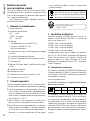
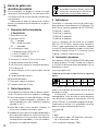
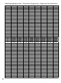
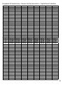
Übertragungsfrequenzen • Transmission frequencies • Fréquences de transmission
GROUP 00 01 02 03 04 05 06 07
CHANNEL MHz MHz MHz MHz MHz MHz MHz MHz
00 672,000 674,500 677,000 679,500 682,000 684,500 687,000 689,500
01 672,025 674,525 677,025 679,525 682,025 684,525 687,025 689,525
02 672,050 674,550 677,050 679,550 682,050 684,550 687,050 689,550
03 672,075 674,575 677,075 679,575 682,075 684,575 687,075 689,575
04 672,100 674,600 677,100 679,600 682,100 684,600 687,100 689,600
05 672,125 674,625 677,125 679,625 682,125 684,625 687,125 689,625
06 672,150 674,650 677,150 679,650 682,150 684,650 687,150 689,650
07 672,175 674,675 677,175 679,675 682,175 684,675 687,175 689,675
08 672,200 674,700 677,200 679,700 682,200 684,700 687,200 689,700
09 672,225 674,725 677,225 679,725 682,225 684,725 687,225 689,725
10 672,250 674,750 677,250 679,750 682,250 684,750 687,250 689,750
11 672,275 674,775 677,275 679,775 682,275 684,775 687,275 689,775
12 672,300 674,800 677,300 679,800 682,300 684,800 687,300
689,800
13 672,325 674,825 677,325 679,825 682,325 684,825 687,325 689,825
14 672,350 674,850 677,350 679,850 682,350 684,850 687,350 689,850
15 672,375 674,875 677,375 679,875 682,375 684,875 687,375 689,875
16 672,400 674,900 677,400 679,900 682,400 684,900 687,400 689,900
17 672,425 674,925 677,425 679,925 682,425 684,925 687,425 689,925
18 672,450 674,950 677,450 679,950 682,450 684,950 687,450 689,950
19 672,475 674,975 677,475 679,975 682,475 684,975 687,475 689,975
20 672,500 675,000 677,500 680,000 682,500 685,000 687,500 690,000
21 672,525 675,025 677,525 680,025 682,525 685,025 687,525 690,025
22 672,550 675,050 677,550 680,050 682,550 685,050 687,550 690,050
23 672,575 675,075 677,575 680,075 682,575 685,075 687,575 690,075
24 672,600 675,100 677,600 680,100 682,600 685,100 687,600 690,100
25 672,625 675,125 677,625 680,125 682,625 685,125 687,625 690,125
26 672,650 675,150 677,650 680,150 682,650 685,150 687,650 690,150
27 672,675 675,175 677,675 680,175 682,675 685,175
687,675 690,175
28 672,700 675,200 677,700 680,200 682,700 685,200 687,700 690,200
29 672,725 675,225 677,725 680,225 682,725 685,225 687,725 690,225
30 672,750 675,250 677,750 680,250 682,750 685,250 687,750 690,250
31 672,775 675,275 677,775 680,275 682,775 685,275 687,775 690,275
32 672,800 675,300 677,800 680,300 682,800 685,300 687,800 690,300
33 672,825 675,325 677,825 680,325 682,825 685,325 687,825 690,325
34 672,850 675,350 677,850 680,350 682,850 685,350 687,850 690,350
35 672,875 675,375 677,875 680,375 682,875 685,375 687,875 690,375
36 672,900 675,400 677,900 680,400 682,900 685,400 687,900 690,400
37 672,925 675,425 677,925 680,425 682,925 685,425 687,925 690,425
38 672,950 675,450 677,950 680,450 682,950 685,450 687,950 690,450
39 672,975 675,475 677,975 680,475 682,975 685,475 687,975 690,475
40 673,000 675,500 678,000 680,500 683,000 685,500 688,000 690,500
41 673,025 675,525 678,025 680,525 683,025 685,525 688,025 690,525
42 673,050 675,550 678,050 680,550 683,050
685,550 688,050 690,550
43 673,075 675,575 678,075 680,575 683,075 685,575 688,075 690,575
44 673,100 675,600 678,100 680,600 683,100 685,600 688,100 690,600
45 673,125 675,625 678,125 680,625 683,125 685,625 688,125 690,625
46 673,150 675,650 678,150 680,650 683,150 685,650 688,150 690,650
47 673,175 675,675 678,175 680,675 683,175 685,675 688,175 690,675
48 673,200 675,700 678,200 680,700 683,200 685,700 688,200 690,700
49 673,225 675,725 678,225 680,725 683,225 685,725 688,225 690,725

17
Frequenze di trasmissione • Frecuencias de transmisión • Częstotliwości kanałów
GROUP 00 01 02 03 04 05 06 07
CHANNEL MHz MHz MHz MHz MHz MHz MHz MHz
50 673,250 675,750 678,250 680,750 683,250 685,750 688,250 690,750
51 673,275 675,775 678,275 680,775 683,275 685,775 688,275 690,775
52 673,300 675,800 678,300 680,800 683,300 685,800 688,300 690,800
53 673,325 675,825 678,325 680,825 683,325 685,825 688,325 690,825
54 673,350 675,850 678,350 680,850 683,350 685,850 688,350 690,850
55 673,375 675,875 678,375 680,875 683,375 685,875 688,375 690,875
56 673,400 675,900 678,400 680,900 683,400 685,900 688,400 690,900
57 673,425 675,925 678,425 680,925 683,425 685,925 688,425 690,925
58 673,450 675,950 678,450 680,950 683,450 685,950 688,450 690,950
59 673,475 675,975 678,475 680,975 683,475 685,975 688,475 690,975
60 673,500 676,000 678,500 681,000 683,500 686,000 688,500 691,000
61 673,525 676,025 678,525 681,025 683,525 686,025 688,525 691,025
62 673,550 676,050 678,550 681,050 683,550 686,050 688,550
691,050
63 673,575 676,075 678,575 681,075 683,575 686,075 688,575 691,075
64 673,600 676,100 678,600 681,100 683,600 686,100 688,600 691,100
65 673,625 676,125 678,625 681,125 683,625 686,125 688,625 691,125
66 673,650 676,150 678,650 681,150 683,650 686,150 688,650 691,150
67 673,675 676,175 678,675 681,175 683,675 686,175 688,675 691,175
68 673,700 676,200 678,700 681,200 683,700 686,200 688,700 691,200
69 673,725 676,225 678,725 681,225 683,725 686,225 688,725 691,225
70 673,750 676,250 678,750 681,250 683,750 686,250 688,750 691,250
71 673,775 676,275 678,775 681,275 683,775 686,275 688,775 691,275
72 673,800 676,300 678,800 681,300 683,800 686,300 688,800 691,300
73 673,825 676,325 678,825 681,325 683,825 686,325 688,825 691,325
74 673,850 676,350 678,850 681,350 683,850 686,350 688,850 691,350
75 673,875 676,375 678,875 681,375 683,875 686,375 688,875 691,375
76 673,900 676,400 678,900 681,400 683,900 686,400 688,900 691,400
77 673,925 676,425 678,925 681,425 683,925 686,425
688,925 691,425
78 673,950 676,450 678,950 681,450 683,950 686,450 688,950 691,450
79 673,975 676,475 678,975 681,475 683,975 686,475 688,975 691,475
80 674,000 676,500 679,000 681,500 684,000 686,500 689,000 691,500
81 674,025 676,525 679,025 681,525 684,025 686,525 689,025 691,525
82 674,050 676,550 679,050 681,550 684,050 686,550 689,050 691,550
83 674,075 676,575 679,075 681,575 684,075 686,575 689,075 691,575
84 674,100 676,600 679,100 681,600 684,100 686,600 689,100 691,600
85 674,125 676,625 679,125 681,625 684,125 686,625 689,125 691,625
86 674,150 676,650 679,150 681,650 684,150 686,650 689,150 691,650
87 674,175 676,675 679,175 681,675 684,175 686,675 689,175 691,675
88 674,200 676,700 679,200 681,700 684,200 686,700 689,200 691,700
89 674,225 676,725 679,225 681,725 684,225 686,725 689,225 691,725
90 674,250 676,750 679,250 681,750 684,250 686,750 689,250 691,750
91 674,275 676,775 679,275 681,775 684,275 686,775 689,275 691,775
92 674,300 676,800 679,300 681,800 684,300
686,800 689,300 691,800
93 674,325 676,825 679,325 681,825 684,325 686,825 689,325 691,825
94 674,350 676,850 679,350 681,850 684,350 686,850 689,350 691,850
95 674,375 676,875 679,375 681,875 684,375 686,875 689,375 691,875
96 674,400 676,900 679,400 681,900 684,400 686,900 689,400 691,900
97 674,425 676,925 679,425 681,925 684,425 686,925 689,425 691,925
98 674,450 676,950 679,450 681,950 684,450 686,950 689,450 691,950
99 674,475 676,975 679,475 681,975 684,475 686,975 689,475 691,975

MONACOR INTERNATIONAL GmbH & Co. KG • Zum Falsch 36 • 28307 Bremen • Germany
Copyright
©
by MONACOR INTERNATIONAL. All rights reserved. A-1254.99.05.11.2019
-
 1
1
-
 2
2
-
 3
3
-
 4
4
-
 5
5
-
 6
6
-
 7
7
-
 8
8
-
 9
9
-
 10
10
-
 11
11
-
 12
12
-
 13
13
-
 14
14
-
 15
15
-
 16
16
-
 17
17
-
 18
18


IMG STAGELINE TXS-606LT Manuale utente
- Categoria
- Microfoni
- Tipo
- Manuale utente
in altre lingue
Documenti correlati
-
IMG STAGELINE TXS-606LT Manuale utente
-
-
-
-
IMG STAGELINE 25.7310 Manuale utente
-
IMG STAGELINE 25.3650 Manuale utente
-
-
-
-