
ELECTRONICS FOR SPECIALISTS ELECTRONICS FOR SPECIALISTS ELECTRONICS FOR SPECIALISTS ELECTRONICS FOR SPECIALISTS ELECTRONICS FOR SPECIALISTS ELECTRONICS
LTR-102
Bestell-Nr. • Order No. 24.1800
MONACOR INTERNATIONAL GmbH & Co. KG • Zum Falsch 36 • 28307 Bremen • Germany
Copyright
©
by MONACOR INTERNATIONAL. All rights reserved.
A-0540.99.04.05.2017
2
3
1
OUTPUT
XLR
OUTPUT
6.3 mm jack
1:1/600 Ω
2:1/150 Ω
INPUT
6.3 mm jack
GROUNDLIFT
NORMAL
INPUT
XLR
NORMAL
REVERSE
2
3
1
RATIO PHASE GND
SOURCE
≤
600 Ω
INPUT OUTPUT
LOAD
≥
2 kΩ
1:1/600 Ω
2:1/150 Ω
NORMAL
REVERSE
NORMAL
GND LIFT
OUTPUT INPUT
GND
2 3 741 65 8
Line Transformer
These operating instructions are intended for users with
basic knowledge in audio technology. Please read the
instructions carefully prior to operating the unit and keep
them for later reference
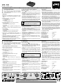
1 Operating Elements and Connections
1 Input via 6.3 mm jack. If this jack is used, the XLR input jack (8)
at the rear will be switched off.
2 RATIO switch for selecting the ratio
Switch not pressed:
1 : 1, output impedance = 600 Ω
Switch pressed:
2 : 1, output impedance = 150 Ω
3 PHASE switch for reversing the phase at the output
Switch not pressed:
phases at the input and output are the same
Switch pressed:
phase at the output is reversed by 180° compared to the
input
4 GND switch for separating the ground connection between
input and output
Switch not pressed:
ground connection between input and output
Switch pressed:
ground separation between input and output
5 Output via 6.3 mm jack. If this jack is used, the XLR output jack
(6) at the rear will be switched off.
6 Output via XLR jack. This jack will be switched off when the
6.3 mm output jack (5) is connected.
7 Additional GND screw connection
8 Input via XLR jack. This jack will be switched off when the
6.3 mm input jack (1) is connected.
2 Safety Notes
The unit corresponds to all relevant directives of the EU and is
therefore marked with .
•
This unit is suitable for audio signals of up to 5 V only.
•
The unit is suitable for indoor use only. Protect it against drip-
ping water and splash water, high air humidity, and heat (ad-
missible ambient temperature range 0 – 40 °C).
•
Only use a dry, soft cloth for cleaning; never use any chemicals
or water.
•
No guarantee claims for the unit and no liability for any result-
ing personal damage or material damage will be accepted if
the unit is used for other purposes than originally intended, if
it is not correctly connect ed or operated, or if it is not re paired
in an expert way.
If the unit is to be put out of operation definitively,
take it to a local recycling plant for a disposal which
is not harmful to the environment.
3 Applications
1. Galvanic isolation between a signal source (e. g. instrument,
microphone, computer, etc.) and the following unit (e. g. ampli-
fier, mixer, effect unit, etc.)
2. Reduction of interferences (e. g. humming) in long signal lines
by reducing the output impedance of the signal source
3. Reduction of interferences in long signal lines via balanced
signal transmission
4. No hum loops when separating the ground between input and
output
5. With wrong phase of the signal, the phase will be reversed
by 180°
6. Adaptation of XLR connection to 6.3 mm jack and vice versa.
7. Adaptation of balanced connection to unbalanced connection
and vice versa
4 Operation
1) Switch off all units before connecting them to the LTR-102.
2) Connect the signal source (instrument, microphone, computer,
etc.) to the INPUT via the 6.3 mm jack (1) or the XLR jack (8).
If both jacks are connected to a unit, the XLR jack will be
switched off. The connection cable between the signal source
and the LTR-102 should be as short as possible in order to
reduce inter ferences.
3) Connect the following unit (e. g. amplifier, mixer, effect unit, etc.)
to the OUTPUT via the 6.3 mm jack (5) or the XLR jack (6). If both
jacks are connected to a unit, the XLR jack will be switched off.
4) Switch on all units which are connected. With the volume
at the amplifier reduced, operate the switches (2 – 4) of the
LTR-102 as follows.
5) Should humming occur, press the GND switch (4) and / or the
RATIO (2) switch to eliminate or reduce the humming. The
RATIO switch (2) should always be pressed when using long
lines (more than 2 m). Thus, the line at the output (5 or 6) will
be less sensitive to interferences.
6) Should a reversal of phase occur during the complete signal
transmission, this can be compensated by press ing the PHASE
switch (3). It is possible to find the optimum setting by listening
to the bass.
5 Specifications
Frequency range: . . . . . . . . . . . . . . . .20 – 25 000 Hz
Ratio: . . . . . . . . . . . . . . . . . . . . . . . . .1: 1/ 2 : 1
Input impedance: . . . . . . . . . . . . . . . .600 Ω
Output impedance: . . . . . . . . . . . . . .600 Ω / 150 Ω
Optimum source impedance: . . . . . . .50 – 600 Ω
Optimum load impedance: . . . . . . . . .≥ 2 kΩ
Max. input voltage
at 1 % THD / 40 Hz: . . . . . . . . . . . . . . .5 V
Subject to technical modification.
Line-Transformator
Diese Anleitung richtet sich an Benutzer mit Grundkennt-
nissen in der Audiotechnik. Bitte lesen Sie die Anleitung
vor dem Betrieb gründlich durch und heben Sie sie für ein
späteres Nachlesen auf.
1 Übersicht
1 Eingang über 6,3-mm-Klinkenbuchse. Beim Anschluss an diese
Buchse wird die rückseitige XLR-Eingangsbuchse (8) abge-
schaltet.
2 Taste RATIO für das Übersetzungsverhältnis
Taste nicht gedrückt:
1 : 1, Ausgangsimpedanz = 600 Ω
Taste gedrückt:
2 : 1, Ausgangsimpedanz = 150 Ω
3 Taste PHASE zum Drehen der Phasenlage am Ausgang
Taste nicht gedrückt:
Phasen am Ein- und Ausgang sind gleich
Taste gedrückt:
Phase am Ausgang ist gegenüber dem Eingang um 180°
gedreht
4 Taste GND zum Trennen der Masseverbindung zwischen dem
Ein- und Ausgang
Taste nicht gedrückt:
die Masse ist zwischen Ein- und Ausgang verbunden
Taste gedrückt:
die Masse ist zwischen Ein- und Ausgang getrennt
5 Ausgang über 6,3-mm-Klinkenbuchse. Beim Anschluss an
diese Buchse wird die rückseitige XLR-Ausgangsbuchse (6)
abgeschaltet.
6 Ausgang über XLR-Buchse. Diese Buchse wird beim Anschluss
der Klinken-Ausgangsbuchse (5) abgeschaltet.
7 Klemmanschluss für einen zusätzlichen Masseanschluss
8 Eingang über XLR-Buchse. Diese Buchse wird beim Anschluss
der Klinken-Eingangsbuchse (1) abgeschaltet.
2 Hinweise für den sicheren Gebrauch
Das Gerät entspricht allen relevanten Richtlinien der EU und trägt
deshalb das -Zeichen.
•
Das Gerät ist nur zur Übertragung von Tonsignalen von bis zu
5 V geeignet.
•
Verwenden Sie das Gerät nur im Innenbereich. Schützen Sie es
vor Tropf- und Spritzwasser, hoher Luftfeuchtigkeit und Hitze
(zulässiger Einsatztemperaturbereich 0 – 40 °C).
•
Verwenden Sie für die Reinigung nur ein trockenes, weiches
Tuch, auf keinen Fall Chemikalien oder Wasser.
•
Wird das Gerät zweckentfremdet, nicht richtig angeschlossen,
falsch bedient oder nicht fachgerecht repariert, kann keine
Garantie für das Gerät und keine Haftung für daraus resultie-
rende Sach- oder Personenschäden übernommen werden.
Soll das Gerät endgültig aus dem Betrieb genommen
werden, übergeben Sie es zur umweltgerechten Ent-
sorgung einem örtlichen Recyclingbetrieb.
3 Einsatzmöglichkeiten
1. Galvanische Trennung zwischen einer Signalquelle (z. B. Instru-
ment, Mikrofon, Computer etc.) und dem nachfolgendem Gerät
(z. B. Verstärker, Mischpult, Effektgerät etc.)
2. Reduzierung von Störeinflüssen (z. B. Brummen) bei langen
Signalleitungen durch Verringerung der Ausgangsimpedanz der
Signalquelle
3. Reduzierung von Störeinflüssen bei langen Signalleitungen
durch symmetrische Signalübertragung
4. Vermeidung von Brummschleifen durch Trennung der Masse
zwischen Ein- und Ausgang
5. Bei falscher Phasenlage des Signals Drehung der Phase um 180°.
6. Anpassung von XLR- auf 6,3-mm-Klinkenanschluss und um-
gekehrt
7. Anpassung von symmetrischen auf asymmetrischen Anschluss
und umgekehrt
4 Bedienung
1) Alle Geräte, die an den LTR-102 angeschlossen werden sollen,
vor dem Anschließen ausschalten!
2) Die Signalquelle (Instrument, Mikrofon, Computer etc.) an den
Eingang INPUT über die Klinkenbuchse (1) oder über die XLR-
Buchse (8) anschließen. Ist an beiden Buchsen ein Gerät ange-
schlossen, wird die XLR-Buchse abgeschaltet. Zur Reduzierung
von Störeinflüssen sollte die Anschlussleitung zwischen Signal-
quelle und dem LTR-102 so kurz wie möglich sein.
3) Das nachfolgende Gerät (z. B. Verstärker, Mischpult, Effektgerät
etc.) an den Ausgang OUTPUT über die Klinkenbuchse (5) oder
über die XLR-Buchse (6) anschließen. Ist an beiden Buchsen
ein Gerät angeschlossen, wird die XLR-Buchse abgeschaltet.
4) Alle angeschlossenen Geräte einschalten. Die Schalter (2 – 4)
des LTR-102 wie folgt betätigen, jedoch immer nur bei am Ver-
stärker reduzierter Lautstärke.
5) Treten Brummprobleme auf, können diese eventuell durch
Drücken der Taste GND (4) und /oder RATIO (2) beseitigt
bzw. verringert werden. Bei langen Leitungen (länger als 2 m)
sollte die Taste RATIO (2) grundsätzlich gedrückt sein. Dadurch
ist die Leitung am Ausgang (5 oder 6) störunempfindlicher.
6) Tritt in der gesamten Signalübertragung eine Phasendrehung
auf, kann diese durch Drücken der Taste PHASE (3) kompensiert
werden. Eventuell kann nach dem Höreindruck der Bässe die
optimale Einstellung ermittelt werden.
5 Technische Daten
Frequenzbereich: . . . . . . . . . . . . . . . . 20 – 25 000 Hz
Übersetzungsverhältnis: . . . . . . . . . . .1: 1/ 2 : 1
Eingangsimpedanz: . . . . . . . . . . . . . .600 Ω
Ausgangsimpedanz: . . . . . . . . . . . . . .600 Ω / 150 Ω
Optimale Quellimpedanz: . . . . . . . . . .50 – 600 Ω
Optimale Lastimpedanz:. . . . . . . . . . .≥ 2 kΩ
Max. Eingangsspannung
bei 1 % Klirrfaktor / 40 Hz: . . . . . . . . . . 5 V
Änderungen vorbehalten.
DeutschEnglish

ELECTRONICS FOR SPECIALISTS ELECTRONICS FOR SPECIALISTS ELECTRONICS FOR SPECIALISTS ELECTRONICS FOR SPECIALISTS ELECTRONICS FOR SPECIALISTS ELECTRONICS
MONACOR INTERNATIONAL GmbH & Co. KG • Zum Falsch 36 • 28307 Bremen • Germany
Copyright
©
by MONACOR INTERNATIONAL. All rights reserved.
A-0540.99.04.05.2017
2
3
1
OUTPUT
XLR
OUTPUT
6.3 mm jack
1:1/600 Ω
2:1/150 Ω
INPUT
6.3 mm jack
GROUNDLIFT
NORMAL
INPUT
XLR
NORMAL
REVERSE
2
3
1
RATIO PHASE GND
SOURCE
≤
600 Ω
INPUT OUTPUT
LOAD
≥
2 kΩ
1:1/600 Ω
2:1/150 Ω
NORMAL
REVERSE
NORMAL
GND LIFT
OUTPUT INPUT
GND
2 3 741 65 8
LTR-102
Réferénce num. • Codice 24.1800
Trasformatore Line
Queste istruzioni sono rivolte a utenti con conoscenze base
nella tecnica audio. Vi preghiamo di leggerle attentamente
prima dell’installazione e di conservarle per un uso futuro.
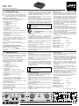
1 Elementi di comando e collegamenti
1 Ingresso mediante presa jack 6,3 mm. Collegando questa presa,
la presa XLR d’ingresso sul retro (8) viene disattivata.
2 Tasto RATIO per stabilire il rapporto di trasformazione
Tasto non premuto:
1 : 1, impedenza d’uscita = 600 Ω
Tasto premuto:
2 : 1, impedenza d’uscita = 150 Ω
3 Tasto PHASE per cambiare la fase all’uscita
Tasto non premuto:
le fasi dell’ingresso e dell’uscita sono uguali
Tasto premuto:
la fase dell’uscita è cambiata di 180° rispetto all’ingresso
4 Tasto GND per separare la massa fra ingresso e uscita
Tasto non premuto:
le masse fra ingresso ed uscita sono collegate
Tasto premuto:
le masse fra ingresso ed uscita sono separate
5 Uscita mediante presa jack 6,3 mm. Collegando questa presa, la
presa XLR d’uscita sul retro (6) viene disattivata.
6 Uscita mediante presa XLR. La presa è disattivata se è collegata
la presa d’uscita jack (5).
7 Contatto per massa supplementare
8 Ingresso mediante presa XLR. La presa è disattivata se è colle-
gata la presa d’ingresso jack (1).
2 Avvertenze di sicurezza
Quest’apparecchio è conforme a tutte le direttive rilevanti dell’UE
e pertanto porta la sigla .
•
L’apparecchio è previsto solo per la trasmissione di segnali
audio fino a 5 V.
•
Far funzionare l’apparecchio solo all’interno di locali. Proteg-
gerlo dall’acqua gocciolante e dagli spruzzi d’acqua, da alta
umidità dell’aria e dal calore (temperatura d’impiego ammessa
fra 0 e 40 °C).
•
Per la pulizia usare solo un panno morbido e asciutto; non im-
piegare in nessun caso prodotti chimici o acqua.
•
Nel caso d’uso improprio, di collegamenti sba gliati, d’impiego
scorretto o di riparazione non a regola d’arte dell’apparecchio,
non si assume nessuna responsabilità per eventuali danni
consequenziali a persone o a cose e non si assume nessuna
garanzia per lo strumento.
Se si desidera eliminare l’apparecchio definitivamente,
consegnarlo per lo smaltimento ad un’istituzione
locale per il riciclaggio.
3 Possibilità d’impiego
1. Isolamento galvanico fra una sorgente di segnali (p. es. stru-
mento, microfono, computer ecc.) e l’apparecchio a valle (p. es.
amplificatore, mixer, unità per effetti ecc.)
2. Riduzione dei disturbi (p. es. ronzio) alla presenza di cavi lunghi
tramite riduzione dell’impedenza d’uscita della sorgente dei
segnali
3. Riduzione di disturbi alla presenza di cavi lunghi tramite tra-
smissione simmetrica dei segnali
4. Assenza di anelli di terra grazie alla separazione della massa
fra ingresso ed uscita
5. Nel caso di fase sbagliata del segnale, la fase può essere cam-
biata di 180°
6. Adattamento da collegamento XLR a jack 6,3 mm e viceversa
7. Adattamento da collegamento simmetrico a collegamento
asimmetrico e viceversa
4 Funzionamento
1) Prima del collegamento, spegnere tutti gli apparecchi da
collegare al trasformatore LTR-102!
2) Collegare la sorgente (strumento, microfono, computer ecc.)
con l’ingresso INPUT delle prese jack (1) o XLR (8). Se tutte e
due le prese sono occupate, la presa XLR viene disattivata. Per
ridurre i disturbi, il cavo di collegamento fra sorgente e match-
box LTR-102 dovrebbe essere il più corto pos sibile.
3) Collegare l’apparecchio a valle (p. es. amplificatore, mixer,
unità per effetti ecc.) con l’uscita OUTPUT delle prese jack (5)
o XLR(6). Se tutte e due le prese sono occupate, la presa XLR
viene disattivata.
4) Accendere tutti gli apparecchi collegati. Azionare i tasti (2 – 4)
del trasformatore LTR-102 come segue, ma sempre con il
volume ridotto sull’amplificatore.
5) Eventuali ronzii potrebbero essere eliminati o ridotti premendo
i tasti GND (4) e / o RATIO (2). Con i cavi lunghi (oltre i 2 m), il
tasto RATIO (2) dovrebbe sempre essere premuto. In tal modo
la linea all’uscita (5 o 6) risente meno i disturbi.
6) Se su tutto il segnale si manifesta uno sfasamento, si può
compensarlo premendo il tasto PHASE (3). È possibile anche
trovare la regolazione ottimale ascoltando i bassi.
5 Dati tecnici
Banda passante: . . . . . . . . . . . . . . . . . 20 – 25 000 Hz
Rapporto di trasformazione:. . . . . . . .1: 1/ 2 : 1
Impedenza d’ingresso: . . . . . . . . . . . .600 Ω
Impedenza d’uscita: . . . . . . . . . . . . . .600 Ω / 150 Ω
Impedenza ottimale di sorgente: . . . .50 – 600 Ω
Impedenza ottimale di carico: . . . . . . ≥ 2 kΩ
Tensione max. d’ingresso con
fattore di distorsione 1 % / 40 Hz: . . . . 5 V
Con riserva di modifiche tecniche.
Transformateur Ligne
Cette notice s’adresse aux utilisateurs avec des connais-
sances techniques de base en audio. Veuillez lire la pré-
sente notice avec attention avant le fonctionnement et
conservez-la pour pouvoir vous y reporter ultérieurement.
1 Eléments et branchements
1 Entrée, prise jack 6,35. Si on utilise cette prise, la prise d’entrée
XLR (8), située sur la face arrière est déconnectée
2 Touche RATIO : rapport de conversion
Touche non enfoncée :
1 : 1, impédance de sortie : 600 Ω
Touche enfoncée :
2 : 1, impédance de sortie : 150 Ω
3 Touche PHASE : inversion de phase en sortie
Touche non enfoncée :
les phases en entrée et sortie sont identiques
Touche enfoncée :
la phase en sortie est à l’opposé (180°) de la phase d’entrée
4 Touche GND : séparation de la masse entre l’entrée et la sortie
Touche non enfoncée :
la masse est reliée entre l’entrée et la sortie
Touche enfoncée :
séparation de la masse entre l’entrée et la sortie
5 Sortie, prise jack 6,35. Si on utilise cette prise, la prise XLR de
sortie (6), située sur la face arrière, est déconnectée
6 Sortie, prise XLR : est déconnectée si on utilise la prise jack
6,35 de sortie (5)
7 Borne pour une connexion masse supplémentaire
8 Entrée, prise XLR : est déconnectée si on utilise la prise d’entrée
jack 6,35 (1)
2 Conseils d’utilisation et de sécurité
Cet appareil répond à toutes les directives nécessaires de l’Union
Européenne et porte donc le symbole .
•
Cet appareil n’est conçu que pour des signaux audio allant
jusqu’à 5 V.
•
Cet appareil n’est conçu que pour une utilisation en intérieur.
Protégez-le de tout type de projections d’eau, des éclabous-
sures, d’une humidité d’air élevée et de la chaleur (plage de
température de fonctionnement autorisée : 0 – 40 °C).
•
Pour le nettoyer, utilisez un chiffon sec et doux, en aucun cas
de produits chimiques ou d’eau.
•
Nous déclinons toute responsabilité en cas de dommages ma-
tériels ou corporels consécutifs si l’appareil est utilisé dans un
but autre que celui pour lequel il a été conçu, s’il n’est pas
correctement branché ou utilisé ou s’il n’est pas réparé par une
personne habilitée ; de même, la garantie deviendrait caduque.
Lorsque l’appareil est définitivement retiré du ser-
vice, vous devez le déposer dans une usine de re-
cyclage adaptée pour contribuer à son élimination
non polluante.
CARTONS ET EMBALLAGE
PAPIER À TRIER
3 Utilisations
1. Isolation galvanique entre une source de signal (par exemple,
un instrument, micro, ordinateur …) et l’appareil suivant
(amplificateur, table de mixage, appareil d’effets spéciaux …)
2. Réduction des interférences (ronflements …) pour des liaisons
longues grâce à une diminution de l’impédance de sortie de
la source
3. Réduction des interférences en cas de liaisons longues grâce à
une transmission symétrique du signal
4. Absence des ronflements par séparation de la masse entre
l’entrée et la sortie
5. Inversion de phase (180°) en cas de phase incorrecte du signal
6. Passage d’un branchement XLR en jack 6,35 et inversement
7. Passage d’un branchement symétrique à un branchement asy-
métrique et inversement
4 Mise en service
1) Avant d’effectuer tout branchement, vérifiez que l’ensemble
des appareils devant être reliés au LTR-102 sont débranchés !
2) Reliez la source (instrument, micro, ordinateur …) à l’entrée
INPUT via la prise jack 6,35 (1) ou la prise XLR (8). Si les deux
prises sont branchées, la prise XLR est déconnectée. Afin de
limiter les interférences, la longueur de la liaison entre la
source et le LTR-102 devrait être aussi courte que possible.
3) Reliez l’appareil suivant (ampli, table de mixage, appareil
d’effects spéciaux …) à la sortie OUTPUT via la prise XLR (6)
ou la prise jack 6,35 (5). Si les deux prises sont branchées, la
prise XLR (6) est débranchée.
4) Allumez maintenant les appareils. Mettez le volume de l’ampli
au minimum puis procédez comme suit :
5) En cas de ronflements, vous pouvez les éliminer ou les réduire:
pour cela, enfoncez la touche GND (4) et / ou RATIO (2). Pour
des liaisons longues (supérieures à 2 m), il devrait toujours
enfoncer la touche RATIO (2) : la ligne en sortie (5) ou (6) est
alors moins sensible aux interférences.
6) Si vous notez une inversion de phase lors de la transmission
du signal, vous pouvez la compenser en enfonçant la touche
PHASE (3). Le choix de l’inversion de phase peut être réalisé
en écoutant les graves.
5 Caractéristiques techniques
Bande passante : . . . . . . . . . . . . . . . .20 – 25 000 Hz
Rapport de conversion : . . . . . . . . . . .1: 1/ 2 : 1
Impédance d’entrée : . . . . . . . . . . . . .600 Ω
Impédance de sortie : . . . . . . . . . . . . .600 Ω / 150 Ω
Impédance optimale de la source : . . .50 – 600 Ω
Impédance optimale de charge : . . . . ≥ 2 kΩ
Tension maximale
d’entrée pour THD 1 % / 40 Hz : . . . . . . 5 V
Tout droit de modification réservé.
FrançaisItaliano
-
 1
1
-
 2
2


in altre lingue
- English: IMG STAGELINE LTR-102 User manual
- français: IMG STAGELINE LTR-102 Manuel utilisateur
- Deutsch: IMG STAGELINE LTR-102 Benutzerhandbuch
Documenti correlati
-
IMG STAGELINE MCL-204 Manuale utente
-
-
-
-
-
-
IMG STAGELINE MMX-11USB Manuale utente
-
IMG STAGELINE DIB-100 Manuale utente
-
-