

2
Ú Table of contents
Ú Instructions for connecting gas and gas conversion (for After-Sales Service only)
Measures to note ....................................................................... 2
Choose which side of the appliance to connect the gas on (*
optional)................................................................................................2
Gas connection.......................................................................... 3
Approved connections.......................................................................3
Natural gas connection (NG)............................................................3
Liquefied gas connection (LPG) ......................................................4
Conversion to a different gas type........................................... 4
Converting to a different gas type ...................................................4
Functional parts for the gas conversion.........................................4
Replacing the burner nozzles...........................................................5
Adjusting or replacing the burner bypass screws and setting
the small flame ....................................................................................5
Converting the appliance from natural gas to liquefied gas ......5
Conversion from liquid gas to natural gas.....................................6
Removing the control panel..............................................................6
Replacing bypass screws .................................................................7
Fitting the control panel.....................................................................7
Replacing the oven burners (optional) ...........................................7
Leak test and function test ....................................................... 8
Check the gas connection ................................................................8
Checking the burner nozzles............................................................8
Checking the bypass valves.............................................................8
Checking the oven burner nozzle (option).....................................8
Check the grill burner nozzle (option) ............................................8
Correct flame formation ............................................................ 9
Burner ...................................................................................................9
Oven ......................................................................................................9
Technical data – Gas ................................................................. 9
Measures to note
The appliance may only be converted to a different gas type
by an approved specialist, in accordance with the
instructions in this manual.
Incorrect connection and incorrect settings may cause
serious damage to the appliance. The appliance
manufacturer accepts no liability for damage and
malfunctions of this kind.
Pay close attention to the symbols indicated on the rating plate.
If there is no symbol for your country, follow the technical
guidelines that apply in your country when making settings.
Before setting up the appliance, determine the gas type and
pressure in the local supply network. Before using the
appliance for the first time, make sure that all settings have
been made correctly.
Pay attention to local and international rules and regulations.
All connection data can be found on the rating plate on the rear
of the appliance.
Enter the data in the following table:
Product number (E no.),
Manufacturing number (FD),
Enter the factory settings for gas type/gas pressure, as well as
the settings for gas type/pressure that apply after the gas
conversion, in the following table.
The changes made to the appliance and the type of connection
play an important role in ensuring that the appliance operates
correctly and safely.
: Risk of gas escape!
■ After connecting the appliance to the gas supply, always
check the connection for leak tightness. The manufacturer
accepts no responsibility for the escape of gas from a gas
connection which has been previously tampered with.
Risk of gas leak!
■ Do not move the appliance by pulling on the gas pipe
(collector). This could damage the gas pipe.
Risk of gas leak!
■ The appliance must not be moved once it has been installed.
If you do move the appliance once it has been installed,
check that the connection is leak-tight.
Switch off the power and gas supply before carrying out any
work.
This appliance must not be installed on boats or in vehicles.
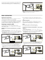
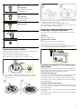
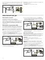
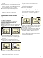
Choose which side of the appliance to
connect the gas on (* optional)
The gas supply to the appliance can be connected on the left
or right. The side on which the gas supply is connected can be
changed if necessary.
Connect the main gas supply.
If you change the side on which the gas supply is connected,
the gas connection piece on the side that is not being used
must be sealed with a blind plug.
To do this:
1. Place the new seal in the blind plug. Make sure the seal is
seated correctly.
2. Secure the gas connection piece to the appliance using a 22
mm spanner and place the blind plug onto the connection
piece using a 24 mm spanner.
E no. FD no.
After-sales service
O
Type of gas / gas pressure
Data on the rating plate
Type of gas / gas pressure
Data after gas conversion

3
Once the side on which the gas supply is connected has been
changed, check that the connection is leak-tight. See the
section entitled "Leak testing" for more information about this.
Note: Use a torque wrench to connect the appliance.
* Option: Only valid for some models.
Gas connection
Approved connections
These instructions apply only when the appliance is set up in
countries that are indicated on the rating plate.
If the appliance is set up, connected and used in a country that
is not indicated on the rating plate, installation and assembly
instructions must be used that contain data and information on
the valid connection conditions in the relevant country.
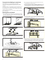
Natural gas connection (NG)
If natural has (NG) is used, the gas supply should be
connected via a gas pipe or a safety gas hose with threaded
fittings at both ends.
Connection in accordance with EN ISO 228 G
^ (TS EN ISO
228 G
^ )
1. Place the new seal in the connection piece. Make sure the
seal is seated correctly.
2. Secure the gas connection piece to the appliance using a 22
mm spanner and place the connection piece into the
connection piece using a 24 mm spanner.
3. Place the new seal into the gas pipe or safety gas hose.
Make sure the seal is seated correctly.
4. Secure the connection piece using a 24 mm spanner. Use a
24 mm spanner to place the threaded fitting of the gas pipe
or safety gas hose on the connection piece and tighten it
firmly.
5. For information on how to carry out leak testing, see the
section entitled "Leak testing". Open the gas connection shut-
off.
: Risk of gas leak!
When connecting the gas pipe or safety gas hose, do not
tighten the gas connection piece on the appliance using a 22
m spanner. This may damage the connection piece.
Notes
■ *G^: EN ISO 228 G^ (TS EN ISO 228 G^)
■ Use a torque wrench to connect the appliance.
Connection in accordance with EN 10226 R
^ (TS 61-210 EN
10226 R
^ )
1. Place the new seal in the connection piece. Make sure the
seal is seated correctly.
2. Secure the gas connection piece to the appliance using a 22
mm spanner and place the connection piece into the
connection piece using a 24 mm spanner.
3. Secure the connection piece using a 24 mm spanner. Use a
24 mm spanner to place the threaded fitting of the gas pipe
or safety gas hose on the connection piece and tighten it
firmly.
1P
6:
6:
6:
6:
1P
*ê
1***
6:
6:
*ê
1***
1P
6:
6:
1P
1***
5ê
6:
6:
1***
1P
5ê

4
4. For information on how to carry out leak testing, see the
section entitled "Leak testing". Open the gas connection shut-
off.
: Risk of gas leak!
When connecting the gas pipe or safety gas hose, do not
tighten the gas connection piece on the appliance using a 22
m spanner. This may damage the connection piece.
Notes
■ *R^: EN 10226 R^ (TS 61-210 EN 10226 R^)
■ Use a torque wrench to connect the appliance.
Liquefied gas connection (LPG)
Caution!
Observe the specific guidelines for each country.
If liquid gas (LPG) is used, the gas supply should be connected
via a gas hose or a fixed connector.
Important information on using a gas hose:
■ Use a safety gas hose or a plastic gas hose (8 or 10 mm in
diameter).
■ It must be attached to the gas connection using an approved
connecting device (e.g. a hose clamp).
■ The hose must be short and completely leak-tight. The hose
must not be longer than 1.5 m. Observe the applicable
guidelines.
■ The gas hose must be replaced once a year.
1. Place the new seal in the connection piece. Make sure the
seal is seated correctly.
2. Secure the gas connection piece to the appliance using a 22
mm spanner and place the connection piece into the
connection piece using a 24 mm spanner.
3. Fit the safety gas hose and use a pipe union or cable clamp
to tighten it securely.
4. For information on how to carry out leak testing, see the
section entitled "Leak testing". Open the gas connection shut-
off.
Note: Use a torque wrench to connect the appliance.
Conversion to a different gas type
Converting to a different gas type
■ The gas connection must be replaced.
■ The burner nozzles must be replaced.
■ Depending on the factory gas setting, the bypass screws in
the burner valves must either be replaced, or screwed in fully.
■ If present, the oven and grill nozzles must also be replaced.
Numbers are printed on the nozzles indicating their diameter.
Further information about the gas types suitable for the
appliance, as well as the corresponding gas nozzles, can be
found in the section entitled "Technical properties - gas".
After the conversion
■ After the appliance has been converted to a different gas
type, you must perform a leak test. See the section entitled
"Leak test".
■ After the appliance has been converted to a different gas
type, the correct flame formation must be tested. See the
section entitled "Correct flame formation".
■ Enter the newly-set type of gas and gas pressure in the table.
See the section entitled "Measures to be observed".
Caution!
After the appliance has been converted to a different gas type,
the labels giving information on the gas type and showing a
star must be affixed at the appropriate point on the rating plate
MAKE SURE THAT YOU DO THIS.
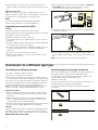
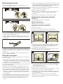
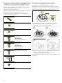
Functional parts for the gas conversion
The functional parts that are required for the gas conversion in
accordance with the instructions are displayed below.
You will find the correct nozzle diameters in the table in the
section entitled "Technical properties - gas".
Always use new seals.
The gas connecting piece to be used may vary depending on
the gas type and country-specific regulations.
(*) These functional parts must be used when the gas is
connected.
6:
/3***
6:
1P
Bypass screw
Burner nozzle
(*) Seal

5
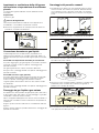
Replacing the burner nozzles
1. Make sure all the knobs on the control panel are turned off.
2. Close the gas connection shut-off.
3. Remove the pan supports and burner parts.
4. Remove the burner nozzles (7 mm socket wrench).
5. If your appliance features a wok burner with side access,
remove the burner nozzle as shown below (7 mm open-
ended spanner).
6. The burner nozzles can be found in the table; see the section
entitled "Technical data – Gas".
Fit the new nozzles into the appropriate burners.
After replacing the nozzles, check that there are no leaks. See
the section entitled "Testing for leaks".
Adjusting or replacing the burner bypass
screws and setting the small flame
The bypass screws regulate the minimum flame height of the
burners.
Preparation
Shut off the gas supply.
: Risk of electric shock!
Interrupt the power supply to the appliance.
1. Turn off the switches on the control panel.
2. Remove the control knobs individually by holding tightly on to
the control panel and pulling them straight out.
Converting the appliance from natural gas to
liquefied gas
If the appliance was set to natural gas at the time of delivery
(factory setting) (NG: G20, G25) and is now being converted to
liquefied gas for the first time (LPG: G30, G31):
For models with safety pilot:
In order to reach the bypass nozzles, the control panel must be
removed. See the section "Removing the control panel".
The bypass nozzles must be tightened as far as they will go.
You must then carry out the work steps in the section "Installing
the control panel".
For models with gas oven (optional):
In order to reach the bypass nozzle underneath the burner tap,
you must remove the control panel. See the section "Removing
the control panel".
The bypass nozzle on the oven burner must be tightened as far
as it will go.
You must then carry out the work steps in the section "Installing
the control panel".
(*) Connecting piece for natural
gas
(NG: G20, G25)
TS 61-210 EN 10226 R
^
EN 10226 R^
(*) Connecting piece for natural
gas
(NG: G20, G25)
TS EN ISO 228 G
^
EN ISO 228 G^
(*) Connecting piece for liquid gas
(LPG: G30, G31)
Gas connecting piece
Dummy plug (shut-off piece)
6:

6
Conversion from liquid gas to natural gas
If the appliance is to be converted from liquid gas
(LPG: G30, G31) to natural gas (NG: G20, G25), or this
conversion has already been performed and is now to be
reversed:
All bypass nozzles on the appliance must be replaced. To do
this, read the section entitled "Removing the control panel".
The instructions in the section entitled "Replacing the bypass
screws" must then be followed.
Then, follow the instructions in the section entitled "Attaching
the control panel".
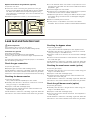
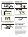
Removing the control panel
1. If the appliance has an upper cover, remove this.To remove
the cover, open it, take hold of it at the sides with both hands,
and pull it upwards. The upper cover will come away. Take
care not to lose the hinges.
2. Remove the pan supports and burner parts.
3. If there are any burner connection screws in the hob, remove
them all.
4. Remove the two screws (T20) at the front right and left of the
hob panel. Do not remove the plastic parts underneath.
5. For models with a wok burner (optional): Remove the four
screws (M4) from the wok burner.
6. Hold the hob panel at the front and tilt it upwards at an angle
of no more than 30°. Use the profile bar, which can be
positioned upright on the front burner fastening, to prop up
the hob panel.
7. Remove the plastic covers from the front profiles on the right
and left (without scuffing or scratching them). Unscrew the
screws (T20) underneath them.
8. Remove the two screws (M4) that are uncovered when you
remove the control knobs (T15).
9. Take hold of the front panel with both hands and slowly pull it
upwards. Release it from its fastening clips. Then carefully
pull the panel forwards to remove it. Ensure that the cables
are not damaged and the connections do not come loose.

7
Replacing bypass screws
1. Loosen the bypass screws with a flat screwdriver (no. 2).
Remove the bypass screws.
2. You can use the table to determine the new bypass screws
that you will need after the gas conversion. See the section
entitled "Technical properties - gas".
3. Check whether the seals on the bypass screw are correctly
seated and work precisely. Only use bypass screws with
intact seals.
4. Insert the new bypass screws and tighten them. Make sure
that all bypass screws are connected to the correct shut-off
valves.
5. At this point, it is essential to carry out a leak test. See the
section entitled "Leak test".
Fitting the control panel
To fit the control panel, follow the instructions for removing it in
the reverse order.
1. Take hold of the front panel with both hands and carefully fit
it into place. Ensure that the cables are not damaged and the
connections do not come loose.Lower the front panel slightly
and place it in the fastening brackets.
2. Screw the two screws (T15 and M4) that you removed from
the control panel back in.
3. Screw the screws (T20) that you removed from the front
profiles back in on the right and left.Refit the plastic covers.
4. Fit the hob panel carefully. Make sure that the plastic parts
underneath the screws do not fall out. Screw the two screws
(T20) back in at the front right and left of the hob panel. If
there are any burner connection screws, screw them all into
the hob panel.
5. For models with a wok burner (optional): Screw the four Torx
screws (M4) that you removed from the wok burner back in.
6. If your cooker has an upper cover, take hold of it on both
sides, hold it upright and push it straight down into the
holder.
7. Fit burner housings of the correct size onto each burner, and
ensure that the spark plug is inserted into the opening on the
edge of the burner housing. Place the enamelled burner caps
in the centre of the matching burner bases.
8. Refit the pan supports. Make sure that the 80 mm-wide pan
support is fitted on the auxiliary burner.
9. Fit the control knobs carefully.
10.At this stage, it is important to check that the burners are
burning correctly; see section entitled "Correct burner
behaviour".
11.Check whether the appliance is functioning correctly.
Replacing the oven burners (optional)
Preparation
Turn off all switches on the control panel.
Shut off the gas supply.
: Risk of electric shock!
Interrupt the power supply to the appliance.
Replacing the nozzle for the oven burner
1. Open the oven door.
2. Loosen the front securing screw in the bottom plate.
3. Hold the bottom plate firmly at the front, lift and remove it.
4. Loosen the burner securing screw and carefully remove the
oven burner. The burner nozzles are now freely accessible.
Make sure that the thermocouple and ignition plug
connections are not damaged.
5. Release the nozzle at the burner access on the rear side of
the oven (using a 7 mm socket wrench).
6. You can use the table to determine the new nozzle that you
will need after the gas conversion. See the section entitled
"Technical properties - gas".
7. Insert and tighten the new nozzle.
8. At this point, it is essential to carry out a leak test. To perform
a leak test, see the section entitled "Leak test".
9. Replace the oven burner, making sure that the thermocouple
and ignition plug connections are not damaged. Retighten
the securing screw.
10.At this point, it is important to check the burner flame
formation. See the section entitled "Correct flame formation".
11.Replace the bottom plate.

8
Replace the nozzle for the grill burner (optional)
1. Open the oven door.
2. Loosen the screw connecting the grill burner to the grill
burner mounting plate and carefully pull the burner straight
out. Make sure that the thermocouple and ignition plug
connections are not damaged. The burner nozzles are now
freely accessible.
3. Release the grill burner nozzle (7 mm socket wrench).
4. You can ascertain which new nozzle is required for the new
gas type using the table. See the section entitled "Technical
properties - gas".
5. Insert and tighten the new nozzle.
6. At this point, it is essential to carry out a leak test. To perform
a leak test, see the section entitled "Leak test".
7. Replace the grill burner, making sure that the thermocouple
and ignition plug connections are not damaged. Retighten
the screws.
8. Slide the seal fully into the burner.
9. At this point, it is important to check the burner flame
formation. See the section entitled "Correct flame formation".
Leak test and function test
: Risk of explosion!
Avoid sparking. Do not use an open flame.
Perform the leak test only with a suitable leakage spray.
In the event of a gas leak
Shut off the gas supply.
Ensure that the room affected is well ventilated.
Check the gas and valve connections again. Repeat the leak
test.
The leak test must be performed by two people, in accordance
with the following instructions.
Check the gas connection
1. Open the gas supply.
2. Spray the gas connection with a leakage spray.
If small bubbles or foam form, indicating a gas leak, follow the
instructions in the section entitled "In the event of a gas leak".
Perform the same steps for the part closed with the blind plug.
Checking the burner nozzles
1. Open the gas supply.
Carry out the leak test separately for each nozzle.
2. Carefully close the hole in the burner nozzle to be checked
using your finger or a suitable device.
3. Spray the nozzle with a leakage spray.
4. Press the function selector and turn it anti-clockwise. This
supplies the nozzle with gas.
If small bubbles or foam form, indicating a gas leak, follow the
instructions in the section entitled "In the event of a gas leak".
Checking the bypass valves
1. Open the gas supply.
Carry out the leak test separately for each bypass screw.
2. Carefully close the hole in the burner nozzle to be checked
using your finger or a suitable device.
3. Spray the nozzle in the burner to be checked with a leakage
spray.
4. Push the control knob and turn it anti-clockwise. This supplies
the nozzle with gas.
If small bubbles or foam form, indicating a gas leak, follow the
instructions in the section entitled "In the event of a gas leak".
Checking the oven burner nozzle (option)
1. Open the gas supply.
2. Carefully close the hole in the oven burner nozzle using your
finger or a suitable device.
3. Spray the nozzle with a leakage spray.
4. Press the function selector and turn it anti-clockwise. This
supplies the nozzle with gas.
If small bubbles or foam form, indicating a gas leak, follow the
instructions in the section entitled "In the event of a gas leak".
Check the grill burner nozzle (option)
1. Open the gas supply.
2. Carefully close the hole in the grill burner nozzle using your
finger or a suitable device.
3. Spray the nozzle with a leakage spray.
4. Turn the oven function selector clockwise. This supplies the
nozzle with gas.
If small bubbles or foam form, indicating a gas leak, follow the
instructions in the section entitled "In the event of a gas leak".

9
Correct flame formation
Burner
The flame formation and temperature development must be
checked for each burner after the appliance is converted to a
different gas type.
In the event of a problem, compare the nozzle values to the
values in the table.
Only for models without safety pilot
1. Ignite the hob burner as described in the operating
instructions.
2. Check the large and small flames for the correct flame
formation. The flame must burn evenly and continuously.
3. Using the burner knob, switch quickly between the large and
small frame. Repeat this process a few times. The gas flame
must not flicker or go out.
Only for models with safety pilot
1. Ignite the hob burner as described in the operating
instructions.
2. Turn the burner knob to the small flame setting.
Check whether the ignition is activated by holding the knob in
the "small flame" position for approximately 1 minute.
3. Check the large and small flames for the correct flame
formation. The flame must burn evenly and continuously.
4. Using the burner knob, switch quickly between the large and
small frame. Repeat this process a few times. The gas flame
must not flicker or go out.
Oven
Lower gas burner or grill burner (optional)
1. Ignite the lower gas burner as described in the operating
instructions.
2. Check the flame formation with the oven door open:
The flame must burn evenly throughout (it may be slightly
uneven in the first few minutes, but after a few minutes, the
flames should burn constantly).
3. To check that the thermocouple is functioning correctly, let
the appliance run for a few minutes.
If necessary, check the settings. If it is not functioning
correctly, replace the bypass screw in the burner.
Technical data – Gas
Different types of gas and the corresponding values are listed
here.
Nozzle values for the auxiliary burner
Nozzle values for the standard burner
*G20/G25 G20 G20 G25 G25 G30/G31 **G30 G25.1 G27 G30
Gas pressure (mbar) 20/25 20 25 20 25 28-30/37 50 25 20 37
Nozzle (mm) 0.72 0.72 0.68 0.77 0.72 0.50 0.43 0.72 0.77 0.47
Bypass nozzle (mm) 0.50 0.50 0.50 0.50 0.50 0.30 0.30 0.50 0.50 0.30
Max. input power (kW) 1 1 1 1 1 1 1 1 1 1
Min. input power (kW) ≤ 0.55 ≤ 0.55 ≤ 0.55 ≤ 0.55 ≤ 0.55 ≤ 0.55 ≤ 0.55 ≤ 0.55 ≤ 0.55 ≤ 0.55
Gas flow at 15 °C and 1013 mbar m³/h 0.095/
0.111
0.095 0.095 0.111 0.111 - - 0.111 0.116 -
Gas flow at 15 °C and 1013 mbar g/h - - - - - 73 73 - - 73
* For France and Belgium
** For G30 (50 mbar), nozzle set HEZ298070 must be ordered from our after-sales service.
*G20/G25 G20 G20 G25 G25 G30/G31 **G30 G25.1 G27 G30
Gas pressure (mbar) 20/25 20 25 20 25 28-30/37 50 25 20 37
Nozzle (mm) 0.97 0.97 0.91 1 0.94 0.65 0.58 0.94 1.00 0.62
Bypass nozzle (mm) 0.58 0.58 0.58 0.58 0.58 0.38 0.38 0.58 0.58 0.38
Max. input power (kW) 1.75 1.75 1.75 1.75 1.75 1.75 1.75 1.75 1.75 1.75
Min. input power (kW) ≤ 0.9 ≤ 0.9 ≤ 0.9 ≤ 0.9 ≤ 0.9 ≤ 0.9 ≤ 0.9 ≤ 0.9 ≤ 0.9 ≤ 0.9
Gas flow at 15 °C and 1013 mbar m³/h 0.167/
0.194
0.167 0.167 0.194 0.194 - - 0.194 0.203 -
Gas flow at 15 °C and 1013 mbar g/h - - - - - 127 127 - - 127
* For France and Belgium
** For G30 (50 mbar), nozzle set HEZ298070 must be ordered from our after-sales service.

10
Nozzle values for the wok burner (optional)
Nozzle values for the high output burner (optional)
Nozzle values for the gas grill burner in the gas oven
(optional)
Nozzle values for the lower burner on the gas oven with
thermostat (optional)
*G20/G25 G20 G20 G25 G25 G30/G31 **G30 G25.1 G27 G30
Gas pressure (mbar) 20/25 20 25 20 25 28-30/37 50 25 20 37
Nozzle (mm) 1.35 1.35 1.20 1.45 1.40 0.96 0.75 1.40 1.46 0.90
Bypass nozzle (mm) 0.88 0.88 0.88 0.88 0.88 0.55 0.55 0.88 0.88 0.55
Max. input power (kW) 3.6 3.6 3.6 3.6 3.6 3.6 3.6 3.6 3.6 3.6
Min. input power (kW) ≤ 1.7 ≤ 1.7 ≤ 1.7 ≤ 1.7 ≤ 1.7 ≤ 1.7 ≤ 1.7 ≤ 1.7 ≤ 1.7 ≤ 1.7
Gas flow at 15 °C and 1013 mbar m³/h 0.342/
0.398
0.342 0.342 0.398 0.398 - - 0.398 0.418 -
Gas flow at 15 °C and 1013 mbar g/h - - - - - 261 261 - - 261
* For France and Belgium
** For G30 (50 mbar), nozzle set HEZ298070 must be ordered from our after-sales service.
*G20/G25 G20 G20 G25 G25 G30/G31 **G30 G25.1 G27 G30
Gas pressure (mbar) 20/25 20 25 20 25 28-30/37 50 25 20 37
Nozzle (mm) 1.16 1.16 1.10 1.34 1.21 0.85 0.75 1.21 1.38 0.80
Bypass nozzle (mm) 0.75 0.75 0.75 0.75 0.75 0.46 0.46 0.75 0.75 0.46
Max. input power (kW) 3 3 3 3 3 3 3 3 3 3
Min. input power (kW) ≤ 1.3 ≤ 1.3 ≤ 1.3 ≤ 1.3 ≤ 1.3 ≤ 1.3 ≤ 1.3 ≤ 1.3 ≤ 1.3 ≤ 1.3
Gas flow at 15 °C and 1013 mbar m³/h 0.285/
0.332
0.285 0.285 0.332 0.332 - - 0.332 0.348 -
Gas flow at 15 °C and 1013 mbar g/h - - - - - 218 218 - - 218
* For France and Belgium
** For G30 (50 mbar), nozzle set HEZ298070 must be ordered from our after-sales service.
*G20/G25 G20 G20 G25 G25 G30 **G30 G25.1
Gas pressure (mbar) 20/25 20 25 20 25 28-30 50 25
Nozzle (mm) 1.00 1.00 0.98 1.13 1.10 0.70 0.62 1.10
Bypass nozzle (mm) - - - - - - - -
Max. input power (kW) 2.1 2.1 2.1 2.1 2.1 2.1 2.1 2.1
Min. input power (kW) - - - - - - - -
Gas flow at 15 °C and 1013 mbar m³/h 0.2/0.233 0.2 0.2 0.233 0.233 - - 0.233
Gas flow at 15 °C and 1013 mbar g/h - - - - - 153 153 -
* For France and Belgium
** For G30 (50 mbar), nozzle set HEZ298070 must be ordered from our after-sales service.
*G20/G25 G20 G20 G25 G25 G30 **G30 G25.1
Gas pressure (mbar) 20/25 20 25 20 25 28-30 50 25
Nozzle (mm) 1.16 1.16 1.10 1.34 1.21 0.85 0.75 1.21
Bypass nozzle (mm) 0.76 0.76 0.67 0.80 0.70 0.48 0.45 0.70
Max. input power (kW) 3 3 3 3 3 3 3 3
Min. input power (kW) - - - - - - - -
Gas flow at 15 °C and 1013 mbar m³/h 0.285/
0.332
0.285 0.285 0.332 0.332 - - 0.332
Gas flow at 15 °C and 1013 mbar g/h - - - - - 218 218 -
* For France and Belgium
** For G30 (50 mbar), nozzle set HEZ298070 must be ordered from our after-sales service.

11
â Indice
â Istruzioni per l'allacciamento e la conversione del gas (solo per il servizio di assistenza tecnica)
Misure da adottare: ..................................................................11
Selezionare il lato per l'allacciamento del gas (* facoltativo).. 11
Allacciamento del gas..............................................................12
Allacciamenti consentiti .................................................................. 12
Allacciamento con gas metano (NG) .......................................... 12
Allacciamento per il gas liquido (LPG)........................................ 13
Passaggio a un altro tipo di gas .............................................13
Passaggio a un altro tipo di gas................................................... 13
Componenti funzionali per il passaggio di gas ......................... 14
Sostituzione degli ugelli del bruciatore........................................ 14
Inserimento o sostituzione delle viti bypass del bruciatore e
impostazione di una fiamma piccola ........................................... 15
Conversione da metano a gas liquido ........................................ 15
Passaggio da gas liquido a gas metano .................................... 15
Smontaggio del pannello comandi .............................................. 15
Sostituzione delle viti bypass......................................................... 16
Montaggio del pannello comandi ................................................. 16
Sostituzione del bruciatore del forno (opzionale)...................... 17
Prova di tenuta e di funzionamento........................................18
Controllo dell'allacciamento del gas ............................................ 18
Controllare gli ugelli del bruciatore. ............................................. 18
Controllo delle viti bypass.............................................................. 18
Controllare l'ugello del bruciatore del forno (opzionale).......... 18
Controllo dell'ugello del bruciatore della griglia (opzionale)... 18
Formazione corretta della fiamma ..........................................18
Bruciatori ........................................................................................... 18
Forno .................................................................................................. 19
Dati tecnici - gas.......................................................................19
Misure da adottare:
Il passaggio dell'apparecchio a un altro tipo di gas deve
essere effettuato solo da un tecnico autorizzato in conformità
alle istruzioni riportate nel presente manuale.
Un collegamento non corretto e impostazioni errate possono
provocare gravi danni all'apparecchio. Il produttore
dell'apparecchio non si assume alcuna responsabilità per
danni e guasti di tale tipo.
Rispettare i simboli riportati sulla targhetta. Qualora non fosse
presente alcun simbolo per il proprio paese, attenersi alle
direttive tecniche del proprio paese durante le installazioni.
Prima di installare l'apparecchio, richiedere informazioni
riguardanti il tipo di gas e la pressione del gas della rete locale.
Prima della messa in funzione dell'apparecchio, assicurarsi che
tutte le impostazioni siano state eseguite correttamente.
Rispettare le direttive e le norme locali e internazionali.
Tutti i dati di allacciamento si trovano sulla targhetta sul lato
posteriore dell'apparecchio.
Inserire i dati nella seguente tabella:
Numero di prodotto (Num. E),
Numero di fabbricazione (FD),
Inserire nella seguente tabella le impostazioni di fabbrica per
tipo/pressione del gas nonché le impostazioni di tipo/
pressione del gas valide dopo il passaggio del gas.
Le modifiche applicate all'apparecchio e il tipo di allacciamento
svolgono un ruolo importante ai fini di un funzionamento
corretto e sicuro.
: Pericolo di fuoriuscita di gas!
■ Dopo qualsiasi intervento sul raccordo del gas controllarne la
tenuta. Il Costruttore non si assume nessuna responsabilità
sulla fuoriuscita di gas da un raccordo che è stato già
manipolato.
Pericolo di perdite di gas!
■ Non spostare l'apparecchio facendo forza sulla conduttura
del gas (collettore) poiché può danneggiarsi.
Pericolo di perdite di gas!
■ Dopo l'installazione l'apparecchio non può più essere
spostato.
Se si sposta l'apparecchio dopo la sua installazione,
verificare la tenuta stagna dell'allacciamento.
Prima di eseguire qualsiasi lavoro, staccare l'alimentazione
della corrente e del gas.
Questo apparecchio non può essere montato su barche o
autovetture.
Selezionare il lato per l'allacciamento del gas
(* facoltativo)
L'allacciamento del gas dell'apparecchio può avvenire sia a
destra che a sinistra. Se necessario è possibile modificare il
lato dell'allacciamento.
Chiudere l'alimentazione del gas principale.
Se si modifica il lato dell'allacciamento del gas, il raccordo
dell'allacciamento del gas sul lato non utilizzato deve essere
chiuso con un tappo cieco.
A tal proposito:
1. collocare la nuova guarnizione nel tappo cieco. Verificare il
corretto posizionamento della guarnizione.
2. Fissare il raccordo dell'allacciamento del gas
sull'apparecchio con una chiave da 22 e collocare il tappo
cieco con una chiave da 24 sul raccordo dell'allacciamento.
Num. E FD
Assistenza clienti
O
Tipo di gas/Pressione del gas
Dati sulla targhetta
Tipo di gas/Pressione del gas
Dati dopo il passaggio del gas

12
Dopo aver modificato il lato dell'allacciamento, effettuare il test
sulla tenuta stagna. A tal proposito vedere il capitolo"Test sulla
tenuta stagna" .
Avvertenza: Per l'allacciamento dell'apparecchio utilizzare una
chiave dinamometrica.
** Opzionale: valido solo per alcuni modelli.
Allacciamento del gas
Allacciamenti consentiti
Queste istruzioni valgono solo per l'installazione
dell'apparecchio nei paesi indicati sulla targhetta.
Qualora l'apparecchio debba essere installato e utilizzato in un
paese non indicato sulla targhetta, occorre far riferimento a
istruzioni di installazione e montaggio che contengano i dati e
le informazioni per le condizioni di allacciamento valide nel
rispettivo paese.
Allacciamento con gas metano (NG)
Se si utilizza il metano (NG), l'allacciamento del gas dovrebbe
essere realizzato mediante un tubo del gas o un tubo flessibile
di sicurezza per gas con raccordi filettati alle due estremità.
Allacciamento conforme a EN ISO 228 G
^ (TS EN ISO 228
G
^ )
1. Inserire la nuova guarnizione nell'elemento dell'allacciamento.
Verificare il corretto posizionamento della guarnizione.
2. Fissare il raccordo dell'allacciamento del gas
sull'apparecchio con una chiave da 22 e collocare l'elemento
dell'allacciamento nel relativo raccordo con una chiave da
24.
3. Collocare la nuova guarnizione nel tubo del gas o nel tubo
flessibile di sicurezza per gas. Verificare il corretto
posizionamento della guarnizione.
4. Fissare l'elemento dell'allacciamento con una chiave 24 e
collocare e stringere l'allacciamento filettato del tubo del gas
o del tubo flessibile di sicurezza per gas con una chiave 24
sull'elemento dell'allacciamento.
5. Per eseguire il test sulla tenuta stagna vedere il capitolo “Test
sulla tenuta stagna". Aprire il dispositivo di chiusura per
l'allacciamento del gas.
: Pericolo di perdite di gas!
Durante l'allacciamento del tubo del gas o del tubo flessibile di
sicurezza per gas, non serrare assolutamente il raccordo
dell'allacciamento del gas sull'apparecchio con una chiave da
22. L'elemento dell'allacciamento potrebbe danneggiarsi.
Avvertenze
■ *G^: EN ISO 228 G^ (TS EN ISO 228 G^)
■ Per l'allacciamento dell'apparecchio utilizzare una chiave
dinamometrica.
Allacciamento conforme a EN 10226 R
^ (TS 61-210 EN
10226 R
^ )
1. Inserire la nuova guarnizione nell'elemento dell'allacciamento.
Verificare il corretto posizionamento della guarnizione.
2. Fissare il raccordo dell'allacciamento del gas
sull'apparecchio con una chiave da 22 e collocare l'elemento
dell'allacciamento nel relativo raccordo con una chiave da
24.
1P
6:
6:
6:
6:
1P
*ê
1***
6:
6:
*ê
1***
1P
6:
6:
1P
1***
5ê

13
3. Fissare l'elemento dell'allacciamento con una chiave da 24 e
collocare e stringere l'allacciamento filettato del tubo del gas
o del tubo flessibile di sicurezza per gas con una chiave da
24 sull'elemento dell'allacciamento.
4. Per eseguire il test sulla tenuta stagna vedere il capitolo “Test
sulla tenuta stagna". Aprire il dispositivo di chiusura per
l'allacciamento del gas.
: Pericolo di perdite di gas!
Durante l'allacciamento del tubo del gas o del tubo flessibile di
sicurezza per gas, non serrare assolutamente il raccordo
dell'allacciamento del gas sull'apparecchio con una chiave da
22. L'elemento dell'allacciamento potrebbe danneggiarsi.
Avvertenze
■ *R^: EN 10226 R^ (TS 61-210 EN 10226 R^)
■ Per l'allacciamento dell'apparecchio utilizzare una chiave
dinamometrica.
Allacciamento per il gas liquido (LPG)
Attenzione!
Osservare le direttive specifiche di ogni Paese.
Se viene utilizzato gas liquido (LPG), l'allacciamento del gas
deve essere realizzato mediante un tubo flessibile per gas o un
collegamento fisso.
Importante durante l'utilizzo di un tubo flessibile per gas:
■ Utilizzare un tubo flessibile di sicurezza per gas o un tubo
flessibile in plastica (diametro 8 o 10 mm).
■ Deve essere dotato di un dispositivo di collegamento
consentito (per esempio una fascetta stringitubo) sul
raccordo del gas.
■ Il tubo flessibile deve essere corto e assolutamente ermetico.
La lunghezza del tubo flessibile deve corrispondere a un
valore massimo di 1,5 m. Osservare le direttive in vigore.
■ Il tubo flessibile per gas deve essere sostituito una volta
all'anno.
1. Inserire la nuova guarnizione nell'elemento dell'allacciamento.
Verificare il corretto posizionamento della guarnizione.
2. Fissare il raccordo dell'allacciamento del gas
sull'apparecchio con una chiave da 22 e collocare l'elemento
dell'allacciamento nel relativo raccordo con una chiave da
24.
3. Inserire il tubo flessibile di sicurezza per gas e stringerlo
bene con un raccordo a vite o un collare di serraggio.
4. Per eseguire il test sulla tenuta stagna vedere il capitolo “Test
sulla tenuta stagna". Aprire il dispositivo di chiusura per
l'allacciamento del gas.
Avvertenza: Per l'allacciamento dell'apparecchio utilizzare una
chiave dinamometrica.
Passaggio a un altro tipo di gas
Passaggio a un altro tipo di gas
■ Il raccordo di allacciamento del gas deve essere sostituito.
■ Gli ugelli del bruciatore devono essere sostituiti.
■ A seconda dell'impostazione del gas in fabbrica, le viti
bypass dei rubinetti del bruciatore possono essere sostituiti o
ruotati fino all'arresto.
■ Se presenti, anche gli ugelli del forno e del grill devono
essere sostituiti.
Sugli ugelli sono riportati numeri che ne indicano il diametro.
Ulteriori informazioni riguardanti i tipi di gas adatti per
l'apparecchio e relativi ugelli del gas sono riportate nella
sezione “Caratteristiche tecniche - Gas".
Dopo il passaggio
■ Dopo il passaggio a un altro tipo di gas è necessario
eseguire una prova di tenuta; vedere la sezione “Prova di
tenuta".
■ Dopo il passaggio a un altro tipo di gas occorre controllare la
corretta formazione della fiamma; vedere la sezione
“Formazione corretta della fiamma".
■ Inserire il nuovo tipo di gas impostato e la nuova pressione
del gas nella tabella. A tal fine vedere la sezione “Misure da
adottare".
Attenzione!
Dopo il passaggio a un altro tipo di gas occorre ATTENERSI
ASSOLUTAMENTE agli adesivi che riportano i dati circa il tipo
di gas e una stella, fissati nel punto preposto sulla targhetta.
6:
6:
1***
1P
5ê
6:
/3***
6:
1P

14
Componenti funzionali per il passaggio di gas
I componenti funzionali necessari per il passaggio del gas
conformemente a queste istruzioni sono illustrati di seguito.
I diametri corretti degli ugelli sono riportati nella tabella alla
sezione “Caratteristiche tecniche - Gas".
Utilizzare sempre guarnizioni nuove.
Il raccordo di allacciamento del gas da utilizzare può variare a
seconda del tipo di gas e delle norme nazionali.
(*) Questi componenti funzionali devono essere utilizzati
durante l'allacciamento del gas.
Sostituzione degli ugelli del bruciatore
1. Spegnere tutti i pulsanti sul pannello comandi.
2. Scollegare il raccordo del gas tramite l'apposito dispositivo.
3. Rimuovere il supporto pentola e i componenti del bruciatore.
4. Smontare gli ugelli del bruciatore (chiave a tubo da 7).
5. Se l'apparecchio dispone di un bruciatore per wok con
accesso laterale, smontare l'ugello del bruciatore come
illustrato qui in basso, (chiave a forchetta 7)
6. Rilevare gli ugelli del bruciatore dalla tabella. Vedere a tal
proposito il capitolo "Dati tecnici-gas".
Montaggio dei rispettivi nuovi ugelli nel bruciatore.
Una volta sostituiti, verificarne la tenuta. Vedere il capitolo “Test
di tenuta" .
Vite bypass
Ugello del bruciatore
(*) Guarnizione
(*) Raccordo di allacciamento per
gas metano
(GN: G20, G25)
TS 61-210 EN 10226 R
^
EN 10226 R^
(*) Raccordo di allacciamento per
gas metano
(GN: G20, G25)
TS EN ISO 228 G
^
EN ISO 228 G^
(*) Raccordo di allacciamento per
gas liquido (GPL: G30, G31)
Raccordo di allacciamento del gas
Chiusura cieca (pezzo di arresto)
6:

15
Inserimento o sostituzione delle viti bypass
del bruciatore e impostazione di una fiamma
piccola
Le viti bypass regolano l'altezza minima della fiamma del
bruciatore.
Preparazione
Chiudere il gas.
: Pericolo di folgorazione!
Interrompere l'alimentazione elettrica verso l'apparecchio.
1. Disattivare i commutatori sul pannello comandi.
2. Rimuovere singolarmente le manopole, facendo forza sul
pannello di comando ed estraendo.
Conversione da metano a gas liquido
Qualora l'apparecchio sia stato fornito (impostazione di
fabbrica) già predisposto per il metano (NG: G20, G25) e si
intenda convertirlo per la prima volta al gas liquido (LPG: G30,
G31):
Per modelli con dispositivo di sicurezza per l'accensione:
Per poter raggiungere gli ugelli bypass è necessario smontare
il pannello comandi. Vedere il capitolo “Smontaggio del
pannello comandi”.
Gli ugelli bypass devono essere serrati fino all'arresto.
Eseguire infine i passaggi illustrati nel capitolo “Montaggio del
pannello comandi”.
Per modelli con forno a gas (opzione):
Per poter raggiungere l'ugello bypass al di sotto del rubinetto
del bruciatore è necessario smontare il pannello comandi.
Vedere il capitolo “Smontaggio del pannello comandi”.
L'ugello bypass del bruciatore del forno deve essere serrato
fino all'arresto.
Eseguire infine i passaggi illustrati nel capitolo “Montaggio del
pannello comandi”.
Passaggio da gas liquido a gas metano
Se l'apparecchio deve passare da gas liquido (GPL: G30, G31)
a gas metano (GN: G20, G25) o questo passaggio è già stato
completato e ora deve essere invertito,
tutte le viti bypass dell'apparecchio devono essere sostituite. A
tal proposito consultare la sezione "Rimozione del pannello di
comando".
Seguire quindi le istruzioni alla sezione “Sostituzione delle viti
bypass".
Seguire quindi le istruzioni riportate nella sezione “Fissaggio del
pannello di comando".
Smontaggio del pannello comandi
1. Se l'apparecchio dispone di una copertura superiore, deve
essere rimossa. Per estrarre la copertura, afferrarla dai lati
con entrambe le mani e spingere verso l'alto. La copertura
superiore si stacca. Accertarsi che le cerniere non vengano
perse.
2. Rimuovere il supporto pentola e i componenti del bruciatore.
3. Se presenti, rimuovere tutte le viti per il collegamento al
bruciatore sul piano cottura.
4. Rimuovere le due viti (T20) davanti a destra e a sinistra sulla
piastra del piano di cottura. Non estrarre le linguette di
plastica che si trovano al di sotto.
5. Per modelli con il bruciatore per wok (opzione): rimuovere le
4 viti (M4) sul bruciatore per wok.

16
6. Afferrare la piastra del piano cottura dalla parte anteriore e
sollevarla verso l'alto di max. 30°. Assicurare la piastra del
piano cottura con la guida profilata che deve essere posta
perpendicolarmente sul fissaggio bruciatori anteriore.
7. Rimuovere le coperture in plastica dei profili frontali a destra
e a sinistra (senza graffiare). Svitare le viti sottostanti (T20).
8. Rimuovere entrambe le viti (M4) che dopo la rimozione delle
manopole di commutazione (T15) sono a vista.
9. Tenere saldamente il pannello frontale con entrambe le mani
e tirarlo lentamente verso l'alto. Estrarlo dalle graffette di
fissaggio. Poi estrarre con cautela il pannello verso l'alto.
Prestare attenzione a non danneggiare i cavi e accertarsi che
i collegamenti non siano allentati.
Sostituzione delle viti bypass
1. Rimuovere le viti bypass con un cacciavite piatto (n. 2).
Svitare le viti bypass.
2. Cercare sulla tabella le nuove viti bypass necessarie
conformemente al passaggio del gas; vedere la sezione
“Caratteristiche tecniche - Gas".
3. Controllare se le guarnizioni delle viti bypass si trovano
esattamente nella propria sede e funzionano correttamente.
Utilizzare solo viti bypass con guarnizioni intatte.
4. Inserire le nuove viti bypass e serrare saldamente. Accertarsi
che tutte le viti bypass siano fissate ai rubinetti di arresto
corretti.
5. A questo punto è assolutamente necessario effettuare una
prova di tenuta; vedere la sezione “Prova di tenuta".
Montaggio del pannello comandi
Il montaggio avviene nell’ordine inverso.
1. Tenere saldamente la piastra del piano cottura con
entrambe le mani e inserirla con cautela. Prestare attenzione
a non danneggiare i cavi e accertarsi che i collegamenti non
siano allentati. Spostarla leggermente verso il basso e
inserirla nelle graffette di fissaggio.
2. Avvitare nuovamente entrambe le viti (T15) (M4) che erano
state rimosse dal pannello comandi.
3. Applicare nuovamente le viti (T20) che erano state rimosse a
destra e a sinistra dai profili frontali. Applicare nuovamente le
coperture in plastica.
4. Inserire con cautela la piastra del piano cottura. Accertarsi
che i componenti in plastica sotto le viti non cadano. Avvitare
nuovamente entrambe le viti (T20) davanti a destra e a
sinistra sulla piastra del piano di cottura. Se presenti,
collocare tutte le viti per il collegamento al bruciatore sula
piastra del piano cottura.
5. Per modelli con bruciatore wok (opzionale): inserire
nuovamente le 4 viti torx (M4) rimosse precedentemente dal
bruciatore wok.

17
6. Tenere saldamente la copertura superiore del fornello (se
presente) su entrambi i lati e inserirla verticalmente nel
supporto.
7. Utilizzare la dimensione corrispondente per l'alloggiamento
del bruciatore e accertarsi che la candela di accensione
venga inserita nell'apertura al lato dell'alloggiamento del
bruciatore. Posizionare i coperchi smaltati del bruciatore al
centro, sulle rispettive parti inferiori dei bruciatori.
8. Collocare nuovamente il supporto pentola. Prestare
attenzione a che il supporto pentole venga posizionato con
80 mm di ampiezza sul bruciatore ausiliario.
9. Inserire con cautela i selettori.
10.In questa fase controllare assolutamente il funzionamento
dei bruciatori. Vedere a tal proposito "Corretto
funzionamento dei bruciatori".
11.Controllare se l'apparecchio funziona senza anomalie.
Sostituzione del bruciatore del forno
(opzionale)
Preparazione
Spegnere tutti i commutatori sul pannello di comando.
Chiudere il gas.
: Pericolo di folgorazione!
Interrompere l'alimentazione elettrica all'apparecchio.
Sostituzione dell'ugello del bruciatore del forno
1. Aprire la porta del forno.
2. Allentare la vite di fissaggio anteriore del pannello di fondo.
3. Tenere il pannello di fondo anteriormente, sollevarlo ed
estrarlo.
4. Svitare la vite di fissaggio del bruciatore ed estrarre con
cautela il bruciatore del forno. Ora gli ugelli del bruciatore
sono facilmente accessibili. Accertarsi di non danneggiare gli
allacciamenti degli elementi termici o degli elettrodi di
accensione.
5. Liberare gli ugelli all'ingresso del bruciatore dal lato
posteriore del forno (con l'aiuto di una chiave a tubo da 7
mm).
6. Verificare i nuovi ugelli necessari dopo il passaggio del gas
sulla tabella; vedere la sezione “Caratteristiche tecniche -
Gas".
7. Inserire e fissare i nuovi ugelli.
8. A questo punto è assolutamente necessario effettuare una
prova di tenuta; consultare la sezione “Prova di tenuta".
9. Riposizionare il bruciatore del forno, accertandosi di non
danneggiare i collegamenti dell'elemento termico e gli
elettrodi di accensione. Fissare nuovamente la vite di
fissaggio.
10.A questo punto è assolutamente necessario controllare la
formazione della fiamma del bruciatore; vedere la sezione
“Formazione corretta della fiamma".
11.Riposizionare il pannello inferiore.
Sostituzione degli ugelli per il bruciatore del grill (opzionale)
1. Aprire la porta del forno.
2. Svitare la vite che tiene uniti la piastra di fissaggio del
bruciatore del grill e il bruciatore del grill, ed estrarre con
cautela il bruciatore. Accertarsi di non danneggiare gli
allacciamenti dell'elemento termico o degli elettrodi di
accensione. Ora gli ugelli del bruciatore sono facilmente
accessibili.
3. Liberare gli ugelli del bruciatore del grill (chiave a tubo da 7
mm).
4. Verificare i nuovi ugelli necessari per il nuovo tipo di gas sulla
tabella; vedere la sezione “Caratteristiche tecniche - Gas".
5. Inserire e fissare i nuovi ugelli.
6. A questo punto è assolutamente necessario effettuare una
prova di tenuta; consultare la sezione “Prova di tenuta".
7. Riposizionare il bruciatore del forno, accertandosi di non
danneggiare i collegamenti dell'elemento termico e gli
elettrodi di accensione. Avvitare nuovamente le viti.
8. Introdurre la guarnizione nel bruciatore fino all'arresto.
9. A questo punto è assolutamente necessario controllare la
formazione della fiamma del bruciatore; vedere la sezione
“Formazione corretta della fiamma".

18
Prova di tenuta e di funzionamento
: Rischio di esplosione!
Evitare la formazione di scintille. Non utilizzare fiamme libere.
Effettuare la prova di tenuta solo con uno spray rivelatore di
perdite adatto.
In caso di perdita di gas
Chiudere il gas.
Aerare abbondantemente la zona coinvolta.
Controllare nuovamente gli allacciamenti del gas e degli ugelli.
Ripetere la prova di tenuta.
La prova di tenuta deve essere eseguita da due persone
seguendo le seguenti indicazioni.
Controllo dell'allacciamento del gas
1. Aprire il gas.
2. Spruzzare la zona intorno all'allacciamento del gas con uno
spray rivelatore di perdite.
Qualora si formassero piccole bolle o schiuma, che denotano
una perdita di gas, seguire le istruzioni riportate nella sezione
"In caso di perdita di gas".
Seguire gli stessi passaggi per la parte chiusa con il tappo
cieco.
Controllare gli ugelli del bruciatore.
1. Aprire il gas.
Effettuare la prova di tenuta di ogni ugello separatamente.
2. Chiudere con cautela il foro dell'ugello del bruciatore da
controllare con il dito o un dispositivo idoneo.
3. Spruzzare l'ugello con uno spray rivelatore di perdite.
4. Premere il selettore delle funzioni e ruotare in senso
antiorario; così il gas arriva all'ugello.
Qualora si formassero piccole bolle o schiuma, che denotano
una perdita di gas, seguire le istruzioni riportate nella sezione
“In caso di perdita di gas".
Controllo delle viti bypass
1. Aprire il gas.
Effettuare la prova di tenuta di ogni vite bypass
separatamente.
2. Chiudere con cautela il foro dell'ugello del bruciatore da
controllare con il dito o un dispositivo idoneo.
3. Spruzzare l'ugello del bruciatore da controllare con uno spray
rivelatore di perdite.
4. Premere la manopola e ruotare in senso antiorario; così il gas
arriva all'ugello.
Qualora si formassero piccole bolle o schiuma, che denotano
una perdita di gas, seguire le istruzioni riportate nella sezione
“In caso di perdita di gas".
Controllare l'ugello del bruciatore del forno
(opzionale)
1. Aprire il gas.
2. Chiudere con cautela il foro dell'ugello del bruciatore del
forno con il dito o un dispositivo idoneo.
3. Spruzzare l'ugello con uno spray rivelatore di perdite.
4. Premere il selettore delle funzioni e ruotare in senso
antiorario; così il gas arriva all'ugello.
Qualora si formassero piccole bolle o schiuma, che denotano
una perdita di gas, seguire le istruzioni riportate nella sezione
“In caso di perdita di gas".
Controllo dell'ugello del bruciatore della
griglia (opzionale)
1. Aprire il gas.
2. Chiudere con cautela il foro dell'ugello del bruciatore della
griglia da controllare con il dito o un dispositivo idoneo.
3. Spruzzare l'ugello con uno spray rivelatore di perdite.
4. Ruotare il selettore delle funzioni del forno in senso orario;
così il gas arriva all'ugello.
Qualora si formassero piccole bolle o schiuma, che denotano
una perdita di gas, seguire le istruzioni riportate nella sezione
“In caso di perdita di gas".
Formazione corretta della fiamma
Bruciatori
La formazione della fiamma e lo sviluppo della temperatura per
ogni ugello devono essere controllati dopo il passaggio a un
altro tipo di gas.
In caso di problemi, confrontare i valori degli ugelli con i valori
riportati nella tabella.
Solo per modelli senza dispositivo di sicurezza per
l'accensione
1. Accendere il bruciatore del piano di cottura come descritto
nel manuale operativo.
2. Controllare la corretta formazione della fiamma nella fiamma
grande e piccola. La fiamma deve bruciare costantemente e
uniformemente.
3. Passare velocemente dalla fiamma grande a quella piccola e
viceversa utilizzando il commutatore del bruciatore. Ripetere
questo passaggio alcune volte. La fiamma del gas non deve
spegnersi o tremolare.
Solo per modelli con dispositivo di sicurezza per
l'accensione
1. Accendere il bruciatore del piano di cottura come descritto
nel manuale operativo.
2. Ruotare il commutatore del bruciatore sulla fiamma piccola.
Controllare se la sicurezza per l'accensione è attiva
mantenendo il commutatore in posizione "Fiamma
piccola" per circa 1 minuto.
3. Controllare la corretta formazione della fiamma nella fiamma
grande e piccola. La fiamma deve bruciare costantemente e
uniformemente.
4. Passare velocemente dalla fiamma grande a quella piccola e
viceversa utilizzando il commutatore del bruciatore. Ripetere
questo passaggio alcune volte. La fiamma del gas non deve
spegnersi o tremolare.

19
Forno
Bruciatore di gas inferiore o bruciatore del grill (opzionale)
1. Accendere il bruciatore del gas inferiore come descritto nel
manuale operativo.
2. Controllare la formazione della fiamma tenendo la porta del
forno aperta:
La fiamma deve bruciare ovunque uniformemente (nei primi
minuti possono verificarsi leggeri cali, dopo alcuni minuti le
fiamme devono però bruciare in modo costante).
3. Per controllare il normale funzionamento degli elementi
termici, lasciare in funzione l'apparecchio per alcuni minuti.
Se necessario, controllare le impostazioni; in caso di
funzionamento difettoso, sostituire le viti bypass del
bruciatore.
Dati tecnici - gas
Sono elencati i diversi tipi di gas e i valori corrispondenti.
Valori ugelli per il bruciatore ausiliario
Valori degli ugelli per il bruciatore normale
Valori degli ugelli per il bruciatore wok (opzione)
*G20/G25 G20 G20 G25 G25 G30/G31 **G30 G25.1 G27 G30
Pressione del gas (mbar) 20/25 20 25 20 25 28-30/37 50 25 20 37
Ugello (mm) 0,72 0,72 0,68 0,77 0,72 0,50 0,43 0,72 0,77 0,47
Ugello bypass (mm) 0,50 0,50 0,50 0,50 0,50 0,30 0,30 0,50 0,50 0,30
Linea di ingresso, max. (kW) 1 1 1 1 1 1 1 1 1 1
Linea di ingresso, min. (kW) ≤0,55 ≤0,55 ≤0,55 ≤0,55 ≤0,55 ≤0,55 ≤0,55 ≤0,55 ≤0,55 ≤0,55
Flusso di gas a 15 °C e 1013 mbar m³/
h
0,095/
0,111
0,095 0,095 0,111 0,111 - - 0,111 0,116 -
Flusso di gas a 15 °C e 1013 mbar g/h - - - - - 73 73 - - 73
* Per Francia e Belgio
** Per G30 (50 mbar) il set ugello, codice HEZ298070, deve essere ordinato presso il servizio di assistenza.
*G20/G25 G20 G20 G25 G25 G30/G31 **G30 G25.1 G27 G30
Pressione del gas (mbar) 20/25 20 25 20 25 28-30/37 50 25 20 37
Ugello (mm) 0,97 0,97 0,91 1 0,94 0,65 0,58 0,94 1,00 0,62
Ugello bypass (mm) 0,58 0,58 0,58 0,58 0,58 0,38 0,38 0,58 0,58 0,38
Linea di ingresso, max. (kW) 1,75 1,75 1,75 1,75 1,75 1,75 1,75 1,75 1,75 1,75
Linea di ingresso, min. (kW) ≤0,9 ≤0,9 ≤0,9 ≤0,9 ≤0,9 ≤0,9 ≤0,9 ≤0,9 ≤0,9 ≤0,9
Flusso di gas a 15 °C e 1013 mbar m³/
h
0,167/
0,194
0,167 0,167 0,194 0,194 - - 0,194 0,203 -
Flusso di gas a 15 °C e 1013 mbar g/h - - - - - 127 127 - - 127
* Per Francia e Belgio
** Per G30 (50 mbar) il set ugello, codice HEZ298070, deve essere ordinato presso il servizio di assistenza.
*G20/G25 G20 G20 G25 G25 G30/G31 **G30 G25.1 G27 G30
Pressione del gas (mbar) 20/25 20 25 20 25 28-30/37 50 25 20 37
Ugello (mm) 1,35 1,35 1,20 1,45 1,40 0,96 0,75 1,40 1,46 0,90
Ugello bypass (mm) 0,88 0,88 0,88 0,88 0,88 0,55 0,55 0,88 0,88 0,55
Linea di ingresso, max. (kW) 3,6 3,6 3,6 3,6 3,6 3,6 3,6 3,6 3,6 3,6
Linea di ingresso, min. (kW) ≤1,7 ≤1,7 ≤1,7 ≤1,7 ≤1,7 ≤1,7 ≤1,7 ≤1,7 ≤1,7 ≤1,7
Flusso di gas a 15 °C e 1013 mbar m³/
h
0,342/
0,398
0,342 0,342 0,398 0,398 - - 0,398 0,418 -
Flusso di gas a 15 °C e 1013 mbar g/h - - - - - 261 261 - - 261
* Per Francia e Belgio
** Per G30 (50 mbar) il set ugello, codice HEZ298070, deve essere ordinato presso il servizio di assistenza.

20
Valori degli ugelli per il bruciatore a potenza elevata
(opzione)
Valori dell'ugello per il bruciatore griglia a gas - forno a gas
(optional)
Valori dell'ugello per il bruciatore inferiore del forno a gas
con termostato (optional)
*G20/G25 G20 G20 G25 G25 G30/G31 **G30 G25.1 G27 G30
Pressione del gas (mbar) 20/25 20 25 20 25 28-30/37 50 25 20 37
Ugello (mm) 1,16 1,16 1,10 1,34 1,21 0,85 0,75 1,21 1,38 0,80
Ugello bypass (mm) 0,75 0,75 0,75 0,75 0,75 0,46 0,46 0,75 0,75 0,46
Linea di ingresso, max. (kW) 3 3 3 3 3 3 3 3 3 3
Linea di ingresso, min. (kW) ≤1,3 ≤1,3 ≤1,3 ≤1,3 ≤1,3 ≤1,3 ≤1,3 ≤1,3 ≤1,3 ≤1,3
Flusso di gas a 15 °C e 1013 mbar m³/
h
0,285/
0,332
0,285 0,285 0,332 0,332 - - 0,332 0,348 -
Flusso di gas a 15 °C e 1013 mbar g/h - - - - - 218 218 - - 218
* Per Francia e Belgio
** Per G30 (50 mbar) il set ugello, codice HEZ298070, deve essere ordinato presso il servizio di assistenza.
*G20/G25 G20 G20 G25 G25 G30 **G30 G25.1
Pressione del gas (mbar) 20/25 20 25 20 25 28-30 50 25
Ugello (mm) 1,00 1,00 0,98 1,13 1,10 0,70 0,62 1,10
Ugello bypass (mm) - - - - - - - -
Linea di ingresso, max. (kW) 2,1 2,1 2,1 2,1 2,1 2,1 2,1 2,1
Linea di ingresso, min. (kW) - - - - - - - -
Flusso di gas a 15 °C e 1013 mbar m³/h 0,2/0,233 0,2 0,2 0,233 0,233 - - 0,233
Flusso di gas a 15 °C e 1013 mbar g/h - - - - - 153 153 -
* Per Francia e Belgio
** Per G30 (50 mbar) il set ugello, codice HEZ298070, deve essere ordinato presso il servizio di assistenza.
*G20/G25 G20 G20 G25 G25 G30 **G30 G25.1
Pressione del gas (mbar) 20/25 20 25 20 25 28-30 50 25
Ugello (mm) 1,16 1,16 1,10 1,34 1,21 0,85 0,75 1,21
Ugello bypass (mm) 0,76 0,76 0,67 0,80 0,70 0,48 0,45 0,70
Linea di ingresso, max. (kW) 3 3 3 3 3 3 3 3
Linea di ingresso, min. (kW) - - - - - - - -
Flusso di gas a 15 °C e 1013 mbar m³/h 0,285/
0,332
0,285 0,285 0,332 0,332 - - 0,332
Flusso di gas a 15 °C e 1013 mbar g/h - - - - - 218 218 -
* Per Francia e Belgio
** Per G30 (50 mbar) il set ugello, codice HEZ298070, deve essere ordinato presso il servizio di assistenza.
La pagina si sta caricando...
La pagina si sta caricando...
La pagina si sta caricando...
La pagina si sta caricando...
-
 1
1
-
 2
2
-
 3
3
-
 4
4
-
 5
5
-
 6
6
-
 7
7
-
 8
8
-
 9
9
-
 10
10
-
 11
11
-
 12
12
-
 13
13
-
 14
14
-
 15
15
-
 16
16
-
 17
17
-
 18
18
-
 19
19
-
 20
20
-
 21
21
-
 22
22
-
 23
23
-
 24
24


in altre lingue
- English: Bosch HR73W530J/03 User manual
Documenti correlati
Altri documenti
-
Hendi 225899 Manuale utente
-
Metos OPLG 80 Istruzioni per l'uso
-
Gorenje GTW7C51B Manuale utente
-
Siemens HG13220EU/20 Manuale utente
-
Barazza 1PSPF64 Istruzioni per l'uso
-
MBM GF99T Installation, Use And Maintenance Instructions
-
Scholtes PMG 41 DCDR Manuale del proprietario
-
Barazza 1PBF104 Istruzioni per l'uso
-
Scholtes PMG 41 DCDR Series Manuale del proprietario
-
Barazza 1PMD70 Istruzioni per l'uso