schmersal BNS 260 AS-R Istruzioni per l'uso
- Tipo
- Istruzioni per l'uso

BNS 260 AS
Operating instructions
Safety sensor
EN
1
1. About this document
1.1 Function
This operating instructions manual provides all the information you
need for the mounting, set-up and commissioning to ensure the safe
operation and disassembly of the switchgear. The operating instructions
must be available in a legible condition and a complete version in the
vicinity of the device.
1.2 Target group: authorised qualified personnel
All operations described in this operating instructions manual must
be carried out by trained specialist personnel, authorised by the plant
operator only.
Please make sure that you have read and understood these operating
instructions and that you know all applicable legislations regarding
occupational safety and accident prevention prior to installation and
putting the component into operation.
The machine builder must carefully select the harmonised standards
to be complied with as well as other technical specifications for the
selection, mounting and integration of the components.
1.3 Explanation of the symbols used
Information, hint, note:
This symbol is used for identifying useful additional
information.
Caution: Failure to comply with this warning notice could
lead to failures or malfunctions.
Warning: Failure to comply with this warning notice could
lead to physical injury and/or damage to the machine.
1.4 Appropriate use
The products described in these operating instructions are developed to
execute safety-related functions as part of an entire plant or machine. It
is the responsibility of the manufacturer of a machine or plant to ensure
the correct functionality of the entire machine or plant.
The safety switchgear must be exclusively used in accordance with
the versions listed below or for the applications authorised by the
manufacturer. Detailed information regarding the range of applications
can be found in the chapter "Product description".
1.5 General safety instructions
The user must observe the safety instructions in this operating
instructions manual, the country specific installation standards as well
as all prevailing safety regulations and accident prevention rules.
Further technical information can be found in the Schmersal
catalogues or in the online catalogue on the Internet:
www.schmersal.net.
The information contained in this operating instructions manual is
provided without liability and is subject to technical modifications.
There are no residual risks, provided that the safety instructions as well
as the instructions regarding mounting, commissioning, operation and
maintenance are observed.
Content
1 About this document
1.1 Function ..............................................1
1.2 Target group: authorised qualied personnel..................1
1.3 Explanation of the symbols used ...........................1
1.4 Appropriate use ........................................1
1.5 General safety instructions ...............................1
1.6 Warning about misuse ...................................2
1.7 Exclusion of liability .....................................2
2 Product description
2.1 Ordering code .........................................2
2.2 Special versions........................................2
2.3 Purpose ..............................................2
2.4 Technical data .........................................2
2.5 Classication ..........................................2
3 Mounting
3.1 General mounting instructions .............................3
3.2 Dimensions ...........................................3
3.3 Axial misalignment......................................3
3.4 Adjustment............................................3
4 Electrical connection
4.1 General information for electrical connection..................3
5 Conguration
5.1 Programming the slave address ...........................4
5.2 Conguration of the safety monitor .........................4
6 Set-up and maintenance
6.1 Functional testing.......................................4
6.2 Maintenance ..........................................4
7 Disassembly and disposal
7.1 Disassembly...........................................4
7.2 Disposal ..............................................4
8 EU Declaration of conformity
x.000 / 07.2019 / v.A. - 101186881-EN / H / 2019-04-07 / AE-Nr. 11169
EN
Operating instructions. . . . . . . . . . . . .pages 1 to 6
Original
CS
Aktuální verzi návodu k použití
ve vašem jazyce naleznete na
www.schmersal.net.
DA
På www.schmersal.net findes
aktuelle betjeningsvejledninger
på EU's officielle sprog.
ES
Encontrará el manual de
instrucciones actual en su
idioma oficial de la UE en
nuestra página de Internet
www.schmersal.net.
FR
Vous trouverez la version
actuelle du mode d’emploi dans
votre langue nationale officielle
sur l’Internet,
www.schmersal.net.
IT
Il manuale d‘istruzioni aggiornato
nella vostra lingua (lingua ufficiale
UE) è scaricabile in Internet
all‘indirizzo
www.schmersal.net.
JP
日本語の取扱説明
書は、インターネット
(www.schmersal.net)から
ダウンロード出来ます。
NL
U vindt de huidige versie van
de gebruikshandleiding in uw
officiële landstaal op het Internet,
www.schmersal.net.
PL
Tutaj znajdziesz aktualną wersję
instrukcji obsługi w Twoim
języku na stronie internetowej
www.schmersal.net.
PT
O manual de instruções actual,
no seu idioma oficial da UE,
encontra-se na nossa página de
Internet www.schmersal.net.
SV
På www.schmersal.net finner
ni de aktuella versionerna av
bruksanvisningen på EU’s
officiella språk.

2
Operating instructions
Safety sensor
BNS 260 AS
EN
1.6 Warning about misuse
In case of improper use or manipulation of the safety
switchgear, personal hazards or damages to machinery
or plant components cannot be excluded. The relevant
requirements of the standard ISO 14119 must be observed.
1.7 Exclusion of liability
We shall accept no liability for damages and malfunctions resulting from
defective mounting or failure to comply with this operating instructions
manual. The manufacturer shall accept no liability for damages
resulting from the use of unauthorised spare parts or accessories.
For safety reasons, invasive work on the device as well as arbitrary
repairs, conversions and modifications to the device are strictly
forbidden; the manufacturer shall accept no liability for damages
resulting from such invasive work, arbitrary repairs, conversions and/or
modifications to the device.
2. Product description
2.1 Ordering code
This operating instructions manual applies to the following types:
BNS 260 ➀-AS-➁
No. Option Description
➀
Connecting cable (2 m)
STG Connecting cable with M12 connector (straight)
STW Connecting cable with M12 connector (angled)
➁
L Door hinge on the left-hand side
R Door hinge on the right-hand side
Actuator
BPS 260 -1 Included in standard version
BPS 260 -2 Mounting angle 90°
2.2 Special versions
For special versions, which are not listed in the order code below 2.1,
these specifications apply accordingly, provided that they correspond to
the standard version.
2.3 Purpose
The safety sensor is used in AS interface systems for monitoring the
position of movable safety guards in accordance with ISO 14119 and
IEC 60947-5-3. The combination of the BNS 260 AS safety sensor,
the BPS 260-1/-2 actuator and the ASM safety monitor ensures the
safe monitoring of the condition of the corresponding safety guard. To
actuate the safety sensor, only the coded BPS 260-1/-2 actuators must
be used.
The safety switchgears are classified according to ISO 14119
as type 4 switching devices.
The safety function consists in safely switching off the code
transmission when the safety guard is opened and maintaining the safe
switched off condition for as long as the safety guard is open.
An AS-Interface Safety at Work component functions on the basis of
an individual code generator (8 x 4 bit). This safety code is cyclically
transmitted over the AS-i network and monitored by the safety monitor.
The component status can be evaluated through a PLC with AS-
Interface master. The safety-related functions are enabled by means of
the AS-i safety monitor.
LED display
The LEDs have the following meaning (to EN 62026-2):
Green LED AS-Interface supply voltage
Red LED AS-Interface communication error or slave address = 0
The user must evaluate and design the safety chain in
accordance with the relevant standards and the required
safety level.
2.4 Technical data
Standards: EN 62026-2, IEC 60947-5-3,
ISO 13849-1, IEC 61508
Enclosure: glass-fibre reinforced thermoplastic,
self-extinguishing
Coding level according to ISO 14119: low
assured switching distance s
ao
: 5 mm
assured switch-off distance s
ar
: 15 mm
Protection class: IP67 to IEC 60529
Termination: cable LSYY (0.23 mm² / AWG 24);
connector M12 x 1, 4-pole
Ambient temperature: –25 °C … +60 °C
Storage and transport temperature: –25 °C … +70 °C
Maximum switching frequency: 1 Hz
Electrical data AS-Interface:
AS-I voltage range: 18.0 ... 31.6 VDC, through AS-Interface, reverse
polarity-proof
AS-I power consumption: ≤ 0.05 A
AS-I Specification: (V 2.1) AS-i slave profile: S-0.B.F.E,
IO code: 0x0,
ID code: 0xB,
ID code1: 0xF,
ID code2: 0xE
AS-interface inputs: Contact 1: Data bits D0 / D1 = static 00 or
dynamic code transmission
Contact 2: Data bits D2 / D3 = static 00
or dynamic code transmission
Parameter port: P0 ... P3: no function, set parameter outputs
to "1111" (0xF)
Input module address: preset to address 0,
can be changed through AS-interface bus master
or hand-held programming device
Diagnostic indication:
AS-i LED green: AS interface supply voltage
AS-i LED red: AS interface communication error
or slave address = 0
For use in NFPA 79 Applications only.
Only for use in Pollution Degree 2 Environment.
Adapters providing field wiring means are available from
the manufacturer. Refer to manufacturers information.
2.5 Classification
Standards: ISO 13849-1, IEC 61508
PL: e
Control Category: 4
PFH: 6.21 x 10
-9
/ h for ≤ 500.000 operations / year
SIL: suitable for SIL 3 applications
Mission time: 20 years

3
BNS 260 AS
Operating instructions
Safety sensor
EN
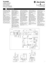
3. Mounting
3.1 General mounting instructions
Please observe the remarks of the standards ISO 12100,
ISO 14119 and ISO 14120.
• Fitting is only authorised in a de-energised condition
• Do not use the sensor and the actuator as a mechanical backstop.
• Any mounting position, provided that the active surfaces are opposite
• Do not subject the safety sensor and actuator to extreme vibrations
and shocks.
To avoid any interference inherent to this kind of system and any
reduction of the switching distances, please observe the following
guidelines:
• Ensure the safety sensor is mounted on a flat surface
• Do not install the safety sensor and the actuator in strong magnetic
fields
• If possible, do not mount the sensor and the actuator on ferromagnetic
material. A non-magnetic spacer of at least 5 mm thick or the original
spacer must be used. The use of non-magnetic fixing screws is
recommended also.
• Keep away from metal chips
• The mounting distance between two sensors should always be at
least 50 mm
The actuator must be permanently fitted to the safety guards
and protected against displacement by suitable measures
(tamperproof screws, gluing, drilling of the screw heads).
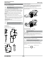
3.2 Dimensions
All measurements in mm.
Sensor with cable, for left hinged door
26
6
2000
13
364
19
22
¤ 4,5
LED
BPS 260-1/-2 actuator
6
13
36
26
4,5
4
19
22
3.3 Axial misalignment
A horizontal and vertical misalignment of the safety sensor and the
actuator is tolerated. The possible misalignment depends on the
distance of the active surface of the sensor and the actuator. The
sensor remains active within the tolerance range.
The specified switching distances refer to opposedly mounted safety
sensors and actuators.
3,5
3,5
3,5
3,5
3,5
3
3
4
5
2
1
0
5
5
5
4
3
2
BPS 260-1
3,5
3,5
3,5
3,5
3,5
3
3
4
5
2
1
0
5
5
5
4
3
2
BPS 260-2
Assured switching distance: s
ao
= 5 mm
assured switch-off distance: sar = 15 mm
Recommended Adjustment
Align the safety sensor and actuator at a distance of 0.5 x s
ao
.
3.4 Adjustment
Adjust the safety sensor and the actuator to the safety guard. The
correct functionality of both safety channels must be checked by means
of the connected safety-monitoring module.
4. Electrical connection
4.1 General information for electrical connection
The electrical connection may only be carried out by
authorised personnel in a de-energised condition.
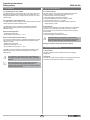
Connection to the AS interface system is realised through the vacant
cable end or an M12 connector. The M12 connector is A-coded.
The wiring configuration of the M12 connector is defined as follows (to
EN 62026-2):
spare
3
2
1
4
AS-Interface - (blue)
AS-Interface + (brown)
spare

4
Operating instructions
Safety sensor
BNS 260 AS
EN
5. Configuration
5.1 Programming the slave address
The slave address is programmed through the connecting cable of the
BNS 260 AS. Depending on the variant used, every address can be
programmed between 1 and 31 through an M12 connector or an open
cable extremity.
5.2 Configuration of the safety monitor
The BNS 260 AS must be configured in the monitoring device as double
channel dependent module with start-up test.
The BNS 260 AS can be configured in the ASIMON configuration
software with the following monitoring devices (also refer to the
ASIMON manual):
Double channel dependent
• Optionally with startup test
• Synchronisation time typically 0.5 – 2.0 s
Double channel dependent with filtering
The use of this monitoring device is especially advantageous on safety
guards where bounce or vibration against the mechanical stop upon
closing is a problem.
• Optionally with startup test
• Stabilising time typically 0.5 -1.0 s
• Synchronisation time typically 5.0 – 10.0 s
The safety-monitoring module is only released after expiration of the
stabilising time; the synchronization time always must exceed the
stabilising time.
The configuration of the safety monitor must be tested and
confirmed by a qualified and authorised safety expert/safety
engineer.
During the project planning, it must be observed that the
length of the cable of each individual safety sensor is
integrated in the overall length (max. 100 m without repeater)
of the AS-Interface network.
6. Set-up and maintenance
6.1 Functional testing
The safety function of the safety components must be tested. The
following conditions must be previously checked and met:
1. Check the switch enclosure for damage
2. Fitting and integrity of the cable connections
3. Connect the BNS 260 AS to the AS-Interface network
4. Set the parameter outputs to "1111" (0xF)
5. Check the correct function of the BNS and BPS system with
configured safety monitor
6.2 Maintenance
In case of correct installation in accordance with the above-described
instructions, the component requires little maintenance. A regular
visual inspection and functional test, including the following steps, is
recommended:
1. Remove particles of dust and soiling
2. Fitting and integrity of the cable connections
Adequate measures must be taken to ensure protection
against tampering either to prevent tampering of the safety
guard, for instance by means of replacement actuators.
Damaged or defective components must be replaced.
7. Disassembly and disposal
7.1 Disassembly
The safety switchgear must be disassembled in a de-energised
condition only.
7.2 Disposal
The safety switchgear must be disposed of in an appropriate manner in
accordance with the national prescriptions and legislations.

5
EN
BNS260AS-C-EN
BNS 260 AS
Operating instructions
Safety sensor
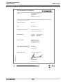
8. EU Declaration of conformity
Place and date of issue: Wuppertal, 21. November 2016
Authorised signature
Philip Schmersal
Managing Director
EU Declaration of conformity
Original K.A. Schmersal GmbH & Co. KG
Möddinghofe 30
42279 Wuppertal
Germany
Internet: www.schmersal.com
We hereby certify that the hereafter described components both in their basic design and construction conform
to the applicable European Directives.
Name of the component: BNS 260 AS
Type: See ordering code
Description of the component: Coded, magnetic safety sensor
with integrated AS-i Safety at Work
Relevant Directives: 2006/42/EG
2014/30/EU
2011/65/EU
Machinery Directive
EMC-Directive
RoHS-Directive
Applied standards: DIN EN 60947-5-3:2014,
DIN EN ISO 14119:2014,
DIN EN ISO 13849-1:2016,
IEC 61508 parts 1-7:2010
Person authorised for the compilation
of the technical documentation:
Oliver Wacker
Möddinghofe 30
42279 Wuppertal
The currently valid declaration of conformity can be
downloaded from the internet at www.schmersal.net.

K.A. Schmersal GmbH & Co. KG
Möddinghofe 30, 42279 Wuppertal
Germany
Phone +49 202 6474-0
Fax +49 202 6474-100
E-Mail: [email protected]
Internet: www.schmersal.com
-
 1
1
-
 2
2
-
 3
3
-
 4
4
-
 5
5
-
 6
6


schmersal BNS 260 AS-R Istruzioni per l'uso
- Tipo
- Istruzioni per l'uso
in altre lingue
Documenti correlati
Altri documenti
-
steute EE RC Si 56 Series Mounting And Wiring Instructions
-
SICK RE31 Magnetic safety switches Istruzioni per l'uso
-
-
-
-
-
 Allen-Bradley TLS-GD2 Installation Instructions Manual
-
-
Eaton SPS-24V-2A5/BNS Guida d'installazione
