
MB071T2IT
Baumer_HOG10-HOG10G_T2_DE_EN_202010_MI_ (20A3)
Istruzioni di montaggio e d‘uso
Mounting and operating instructions
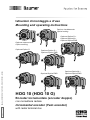
HOG 10 (HOG 10 G)
Encoder incrementale (encoder doppio)
con morsettiera radiale
Incremental encoder (Twin encoder)
with radial terminal box
Opzione/Option M +
Opzione/Option EMS
Opzione riscaldamento
Option heating
Opzione messa a terra
Option earthing
Opzione/Option G +
Opzione/Option M +
Opzione/Option EMS
Opzione/Option EMS
Opzione/Option G +
Opzione/Option EMS
Opzione/Option G

Baumer_HOG10-HOG10G_T2_DE_EN_202010_MI_ (20A3)
MB071T2IT
Sommario
Sommario
1 Indicazioni generali ................................................................................................................................................... 1
2 Uso in ambienti potenzialmente esplosivi
................................................................................................3
3 Indicazioni di sicurezza
..........................................................................................................................................5
4 Preparazione
..................................................................................................................................................................7
4.1 Dotazione base
...............................................................................................................................................7
4.2 Ambito di fornitura della morsettiera
.................................................................................................... 8
4.3 Componenti necessari per il montaggio (non inclusi nella dotazione)
...............................9
4.4 Componenti necessari per lo smontaggio (non inclusi nella dotazione)
........................ 10
4.5 Strumenti necessari (non inclusi nella dotazione)
..................................................................... 10
5 Montaggio
......................................................................................................................................................................11
5.1 Fase 1
.................................................................................................................................................................11
5.2 Fase 2
.................................................................................................................................................................11
5.3 Fase 3 - albero cavo aperto su un lato
............................................................................................. 12
5.4 Fase 3 - albero cavo conico
................................................................................................................... 13
5.5 Fase 4
................................................................................................................................................................ 14
5.6 Fase 5 - braccio di reazione
.................................................................................................................. 15
5.7 Indicazioni per evitare errori di misurazione
................................................................................. 16
5.8 Fase 6
.................................................................................................................................................................17
5.9 Istruzioni di montaggio
..............................................................................................................................17
5.10 Fase 7
................................................................................................................................................................ 18
5.11 Fase 8 e 9 - morsettiera
........................................................................................................................... 18
5.12 Fase 10 - morsettiera
................................................................................................................................ 19
5.13 Fase 11 - morsettiera
................................................................................................................................ 19
5.14 Fase 12 - morsettiera
................................................................................................................................ 20
6 Dimensioni
................................................................................................................................................................... 21
6.1 Albero cavo aperto su un lato
............................................................................................................... 21
6.2 Albero cavo conico
..................................................................................................................................... 23
7 Collegamento elettrico
........................................................................................................................................ 25
7.1 Assegnazione terminali
............................................................................................................................ 25
7.2 Segnali di uscita
........................................................................................................................................... 25
7.3 Assegnazione dei morsetti
..................................................................................................................... 26
7.4 Opzione EMS (Enhanced Monitoring System): LED di stato / uscita errori
................. 27
7.5 Opzione riscaldamento: collegamento elettrico per riscaldamento
................................. 28
7.6 Cavo del sensore (accessorio)
............................................................................................................. 28
8 Uso e manutenzione
.............................................................................................................................................. 29
8.1 Opzione messa a terra: sostituzione della spazzola al carbonio
....................................... 29
9 Smontaggio
................................................................................................................................................................. 30
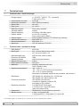
10 Dati tecnici
................................................................................................................................................................... 33
10.1 Dati tecnici - elettrici
.................................................................................................................................. 33
10.2 Dati tecnici - meccanici
............................................................................................................................ 33
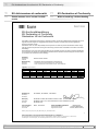
11 EU dichiarazione di conformità
..................................................................................................................... 35
11.1 Senza messa a terra / senza riscaldamento
................................................................................ 35
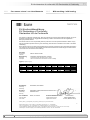
11.2 Con messa a terra / con riscaldamento
.......................................................................................... 36
12 Accessori
...................................................................................................................................................................... 37

MB071T2IT
Baumer_HOG10-HOG10G_T2_DE_EN_202010_MI_ (20A3)
Table of contents
Table of contents
1 General notes ................................................................................................................................................................ 2
2 Operation in potentially explosive environments
.................................................................................4
3 Security indications
.................................................................................................................................................. 6
4 Preparation
.....................................................................................................................................................................7
4.1 Scope of delivery of the basic device
..................................................................................................7
4.2 Scope of delivery terminal box
................................................................................................................ 8
4.3 Required for mounting (not included in scope of delivery)
....................................................... 9
4.4 Required for dismounting (not included in scope of delivery)
.............................................. 10
4.5 Required tools (not included in scope of delivery)
..................................................................... 10
5 Mounting
.........................................................................................................................................................................11
5.1 Step 1
.................................................................................................................................................................11
5.2 Step 2
.................................................................................................................................................................11
5.3 Step 3 - Blind hollow shaft
...................................................................................................................... 12
5.4 Step 3 - Cone shaft
.................................................................................................................................... 13
5.5 Step 4
................................................................................................................................................................ 14
5.6 Step 5 - Torque arm
................................................................................................................................... 15
5.7 How to prevent measurement errors
................................................................................................. 16
5.8 Step 6
................................................................................................................................................................ 17
5.9 Mounting instruction
.................................................................................................................................. 17
5.10 Step 7
................................................................................................................................................................ 18
5.11 Step 8 and 9 - Terminal box
................................................................................................................... 18
5.12 Step 10 - Terminal box
.............................................................................................................................. 19
5.13 Step 11 - Terminal box
.............................................................................................................................. 19
5.14 Step 12 - Terminal box
.............................................................................................................................. 20
6 Dimensions
.................................................................................................................................................................. 21
6.1 Blind hollow shaft
........................................................................................................................................ 21
6.2 Cone shaft
....................................................................................................................................................... 23
7 Electrical connection
............................................................................................................................................ 25
7.1 Terminalsignicance
................................................................................................................................. 25
7.2 Output signals
............................................................................................................................................... 25
7.3 Terminal assignment
................................................................................................................................. 26
7.4 Option EMS (Enhanced Monitoring System): Status LED / Error output
....................... 27
7.5 Option heating: Power supply for heating
....................................................................................... 28
7.6 Sensor cable HEK 8 (accessory)
........................................................................................................ 28
8 Operation and maintenance
............................................................................................................................. 29
8.1 Option earthing: Replace of the carbon brushes
........................................................................ 29
9 Dismounting
................................................................................................................................................................ 30
10 Technical data
............................................................................................................................................................ 34
10.1 Technical data - electrical ratings
....................................................................................................... 34
10.2 Technical data - mechanical design
.................................................................................................. 34
11 EU Declaration of Conformity
......................................................................................................................... 35
11.1 Without earthing / without heating
...................................................................................................... 35
11.2 With earthing / with heating
................................................................................................................... 36
12 Accessories
................................................................................................................................................................. 37

1
Baumer_HOG10-HOG10G_T2_DE_EN_202010_MI_ (20A3)
MB071T2IT
1 Indicazioni generali
1 Indicazioni generali
1.1 Spiegazione dei simboli:
Pericolo
Avvertenza per possibili pericoli
Indicazioni da osservare
Indicazioni per garantire un funzionamento corretto dell‘apparecchio
i
Informazione
Consiglio per l‘utilizzo dell‘apparecchio
1.2 L‘ encoder incrementale HOG 10 (HOG 10 G) è un apparecchio di misurazione di precisio-
ne opto-elettronico, che deve essere utilizzato con cura solo da personale tecnico qualicato.
1.3 L‘aspettativa della vita utile dell‘apparecchio dipende dai cuscinetti a sfera, dotati con una
lubricazione permanente.
1.4 Opzione messa a terra: Le spazzole di messa a terra hanno un‘aspettativa di vita utile dipen-
dente dalla continuità elettrica e, in genere, corrispondente a quella die cuscinetti a sfera.
1.5
Campo di temperatura di stoccaggio dell‘apparecchio è compreso tra -15 °C e
+70 °C.
1.6
Campo di temperatura operativa dell‘apparecchio è compreso tra -40 °C e +100 °C
(impulsi per ogni giro >3072: -25...+100 °C, opzione riscaldamento: -50...+100 °C),
uso limitato in ambienti esplosivi, v. cap. 2, misurati nell‘alloggiamento.
1.7
EU dichiarazione di conformità ai sensi delle direttive europee.
1.8 L‘apparecchio è approvato UL (non applicabile per l‘utilizzo in ambienti potenzialmente esplosivi).
1.9 Viene offerta una garanzia di 2 anni nell‘ambito delle condizioni dell‘associazione centrale
dell‘industria elettrica (ZVEI).
1.10 L‘apparecchio può essere aperto solo nella modalità descritta nelle presenti istruzioni. Ripara-
zioni di manutenzione che richiedono un‘apertura completa dell‘apparecchio devono essere
eseguite dal produttore. Non è consentito modicare in alcun modo l‘apparecchio.
1.11 In caso di domande e/o forniture successive comunicare sempre i dati riportati sulla targhet-
ta identicativa dell‘apparecchio, in particolare tipo e numero di serie.
1.12
Smaltimento (protezione ambientale):
Le apparecchiature elettriche ed elettroniche usate non devono essere smaltite con i
riuti domestici. Il prodotto contiene preziose materie prime che possono essere
riciclate. Ove possibile, i vecchi apparecchi devono essere smaltiti localmente presso
l‘apposito centro di raccolta. Se necessario, Baumer offre ai clienti la possibilità di smaltire i
prodotti Baumer in modo professionale. Per ulteriori informazioni, visitare il sito web www.
baumer.com.
i
Attenzione!
Danni al sigillo apposto sull‘apparecchio annullano la garanzia.

MB071T2IT
Baumer_HOG10-HOG10G_T2_DE_EN_202010_MI_ (20A3)
2
General notes 1
1 General notes
1.1 Symbol guide:
Danger
Warnings of possible danger
General information for attention
Informations to ensure correct device operation
i
Information
Recommendation for device handling
1.2 The incremental encoder HOG 10 (HOG 10 G) is an opto electro nic precision measurement
device which must be handled with care by skilled personnel only.
1.3 The expected service life of the device depends on the ball bearings, which are equipped with
a permanent lubrication.
1.4 Option earthing: The expected service life of the carbon brushes depends on the electrical
current and is usually consistent with the service life of the ball bearings.
1.5
The storage temperature range of the device is between -15 °C and +70 °C.
1.6
The operating temperature range of the device is between -40 °C and +100 °C
(>3072 pulses per revolution: -25...+100 °C, option heating: -50...+100 °C), restricted
in potentially explosive environments, see section 2, measured at the housing.
1.7
EU Declaration of Conformity meeting to the European Directives.
1.8 The device is UL approved (not applicable for operation in potentially explosive atmospheres).
1.9 We grant a 2-year warranty in accordance with the regulations of the ZVEI (Central Association
of the German Electrical Industry).
1.10 The device may be only opened as described in this instruction. Repair or maintenance work
that requires opening the device completely must be carried out by the manufacturer. Altera-
tions of the device are not permitted.
1.11 In the event of queries or subsequent deliveries, the data on the device type label must be
quoted, especially the type designation and the serial number.
1.12
Disposal (environmental protection):
Do not dispose of electrical and electronic equipment in household waste. The product
contains valuable raw materials for recycling. Whenever possible, waste electrical and
electronic equipment should be disposed locally at the authorized collection point. If
necessary, Baumer gives customers the opportunity to dispose of Baumer products profession-
ally. For further information see www.baumer.com.
i
Warning!
Damaging the seal on the device invalidates warranty.

3
Baumer_HOG10-HOG10G_T2_DE_EN_202010_MI_ (20A3)
MB071T2IT
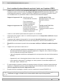
2 Uso in ambienti potenzialmente esplosivi (solo con l‘opzione ATEX)
L‘apparecchio è conforme alla normativa 2014/34/EU per ambienti potenzialmente esplosivi.
Può essere usato conformemente alla categoria di apparecchi 3 G (atmosfera esplosiva - gas)
e 3 D (atmosfera esplosiva - polvere). Eccezione: apparecchi con spazzole di messa a terra o
con riscaldamento non può essere usata in ambienti potenzialmente esplosivi.
Categoria di apparecchi 3 G:
- Identicazione Ex: II 3 G Ex nA IIC T4 Gc
- Conformità alle normative: EN 60079-0:2012 + A11:2013
EN 60079-15:2010
- Tipo di protezione: nA
- Classe di temperatura: T4
- Gruppo di apparecchi: II
Categoria di apparecchi 3 D:
- Identicazione Ex: II 3 D Ex tc IIIC T135°C Dc
- Conformità alle normative: EN 60079-31:2014
- Principio di protezione: Protezione tramite involucro
-
Temperatura superciale max.
: +135 °C
- Gruppo di apparecchi: III
L‘utilizzo in altri ambienti potenzialmente esplosivi non è ammesso.
2.1 Il dispositivo deve essere usato in un ambiente esplosivo a una temperatura ambiente compre-
sa tra -20 °C e +40 °C.
2.2 L‘operatore dell‘impianto deve garantire che eventuali depositi di polvere non superino uno
spessore massimo di 5 mm (conformemente alle disposizioni della norma EN 60079-14).
2.3 Elenchi UL eventualmente riportati altrove non sono validi per l‘utilizzo in ambienti esplosi-
vi.
2.4 L‘apparecchio può essere usato solo se ...
– i dati sulla targhetta identicativa dell‘apparecchio corrispondono alle condizioni in loco
ammesse per ambienti esplosivi (gruppi di apparecchi, categoria, zona, classe di tempera-
tura e/o temperatura superciale massima),
– i dati sulla targhetta identicativa dell‘apparecchio corrispondono alla rete di alimentazione
elettrica,
– l‘apparecchio non è danneggiato (nessun danno dovuto a trasporto e stoccaggio) e
– viene garantito che durante il montaggio non siano presenti un atmosfera esplosiva, oli,
acidi, gas, vapori, radiazioni ecc.
2.5 È vietato eseguire qualsiasi modica alle apparecchiature utilizzate in ambienti potenzialmente
esplosivi. Le riparazioni possono essere eseguite solo da entità autorizzate dal produttore. In
caso di trasgressione decade l‘approvazione Ex.
2.6 Durante la fase di montaggio e messa in servizio osservare la norma EN 60079-14.
2 Uso in ambienti potenzialmente esplosivi
L‘apparecchio deve essere utilizzato conformemente alle istruzioni di montaggio e uso.
Osservare le leggi, le direttive e le norme relative allo scopo d‘uso previsto.

MB071T2IT
Baumer_HOG10-HOG10G_T2_DE_EN_202010_MI_ (20A3)
4
2 Operation in potentially explosive environments (only with option ATEX)
The device complies with the directive 2014/34/EU for potentionally explosive atmospheres.
It can be used in accordance with equipment categories 3 G (explosive gas atmosphere) and
3 D (explosive dust atmosphere). Exception: Versions with earthing or with heating must not be
used in potentionally explosive atmospheres.
Equipment category 3 G: - Ex labeling: II 3 G Ex nA IIC T4 Gc
- Conforms to standard: EN 60079-0:2012 + A11:2013
EN 60079-15:2010
- Type of protection: nA
- Temperature class: T4
- Group of equipment: II
Equipment category 3 D: - Ex labeling: II 3 D Ex tc IIIC T135°C Dc
- Conforms to standard: EN 60079-31:2014
- Protective principle: Protection by enclosure
- Max. surface temperature: +135 °C
- Group of equipment: III
The operation in other explosive atmospheres is not permissible.
2.1 In Ex areas the device must only be used within the ambient temperature range from -20 °C to
+40 °C.
2.2 The plant operator must ensure that any possible dust deposit does not exceed a thickness of
5 mm (in accordance with EN 60079-14).
2.3 An UL listing that may be stated elsewhere is not valid for use in explosive environ-
ments.
2.4 Operation of the device is only permissible when ...
– the details on the type label of the device match the on-site conditions for the permissible
Ex area in use (group of equipment, equipment category, zone, temperature class or maxi-
mum surface temperature),
– the details on the type label of the device match the electrical supply network,
– the device is undamaged (no damage resulting from transport or storage), and
– it has been checked that there is no explosive atmosphere, oils, acids, gases, vapors,
radiation etc. present when mounting.
2.5 It is not permissible to make any alteration to equipment that is used in potentially explosive en-
vironments. Repairs may only be carried out by authorized authorities provided by the manufac-
turer. Contravention invalidates the EX approval.
2.6 Attend the norm EN 60079-14 during mount and operation.
Operation in potentially explosive environments 2
The device must be operated in accordance with the stipulations of the mounting and
operating instructions. The relevant laws, regulations and standards for the planned
application must be observed.

5
Baumer_HOG10-HOG10G_T2_DE_EN_202010_MI_ (20A3)
MB071T2IT
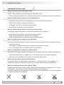
3 Indicazioni di sicurezza
3 Indicazioni di sicurezza
3.1 Rischio di lesioni dovute ad alberi rotanti
Capelli e abiti potrebbero rimanere impigliati negli alberi rotanti.
• Prima di eseguire qualsiasi lavoro, disattivare tutte le tensioni operative e arrestare la macchina.
3.2 Rischio di distruzione a causa di carica elettrostatica
I componenti elettronici contenuti nell‘apparecchio sono sensibili ad alte tensioni.
• Non toccare contatti né componenti elettronici.
• Proteggere i terminali di uscita da tensioni esterne.
• Non superare la massima tensione operativa.
3.3 Rischio di distruzione a causa di sovraccarico meccanico
Un ssaggio rigido può causare un sovraccarico dovuto a forze costrittive.
• Non limitare mai la capacità di movimento dell‘apparecchio.
Osservare assolutamente le indicazioni di montaggio.
• Osservare assolutamente le distanze e/o gli angoli specicati.
3.4 Rischio di distruzione a causa di urto meccanico
Scuotimenti violenti, per esempio impatti di martelli, possono causare la distruzione della scansione.
• Non usare violenza.
Il montaggio si esegue facilmente se si osservano le procedure corrette.
• Per lo smontaggio usare un attrezzo adatto per l‘estrazione.
3.5 Rischio di distruzione a causa di contaminazione
Sporcizia può penetrare all‘interno dell‘apparecchio causando cortocircuiti e danni alla scansione.
• Durante qualsiasi lavoro con l‘apparecchio è necessario osservare un‘assoluta pulizia.
• Non lasciare mai penetrare olio o grasso all‘interno dell‘apparecchio.
3.6 Rischio di distruzione a causa di uidi adesivi
I uidi adesivi possono danneggiare la scansione e i cuscinetti a sfera. Lo smontaggio di un
apparecchio ssato a un albero con adesivo può causare la distruzione dell‘apparecchio.
3.7 Rischio di esplosione (solo con l‘opzione ATEX)
L‘apparecchio può essere usato in ambienti potenzialmente esplosivi di categoria 3 D e 3 G. Non
è consentito il funzionamento in altre atmosfere potenzialmente esplosive.
Eccezione: apparecchi con spazzole di messa a terra o con riscaldamento non può essere usata
in ambienti potenzialmente esplosivi.

MB071T2IT
Baumer_HOG10-HOG10G_T2_DE_EN_202010_MI_ (20A3)
6
Security indications 3
3 Security indications
3.1 Risk of injury due to rotating shafts
Hair and clothes may become tangled in rotating shafts.
• Before all work switch off all voltage supplies and ensure machinery is stationary.
3.2 Risk of destruction due to electrostatic charge
Electronic parts contained in the device are sensitive to high voltages.
• Do not touch plug contacts or electronic components.
• Protect output terminals against external voltages.
• Do not exceed maximum voltage supply.
3.3 Risk of destruction due to mechanical overload
Rigid mounting may give rise to constraining forces.
• Never restrict the freedom of movement of the device.
The mounting instructions must be followed.
• Itisessentialthatthespeciedclearancesand/oranglesareobserved.
3.4 Risk of destruction due to mechanical shock
Violent shocks, e. g. due to hammer impacts, can lead to the destruction of the sensing system.
• Never use force.
Mounting is simple when correct procedure is followed.
• Use suitable puller for dismounting.
3.5 Risk of destruction due to contamination
Dirt penetrating inside the device can cause short circuits and damage the sensing system.
• Absolute cleanliness must be maintained when carrying out any work on the device.
• Never allow lubricants to penetrate the device.
3.6 Risk of destruction due to adhesive uids
Adhesiveuidscandamagethesensingsystemandtheballbearings.Dismountingadevice,
secured to a shaft by adhesive may lead to the destruction of the device.
3.7 Explosion risk (only with option ATEX)
You can use the device in areas with explosive atmospheres of category 3 D and 3 G. The op-
eration in other explosive atmospheres is not permissible.
Exception: Versions with earthing or with heating must not be used in potentionally explosive
atmospheres

7
Baumer_HOG10-HOG10G_T2_DE_EN_202010_MI_ (20A3)
MB071T2IT
8 9
2
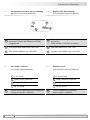
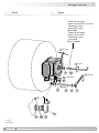
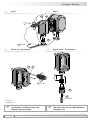
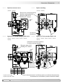
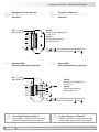
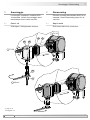
4 Preparazione / Preparation
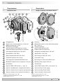
1
Alloggiamento
2
Albero cavo o conico aperto su un lato con
dado meccanico da 17 mm
3
Elemento di bloccaggio
(solo per albero cavo aperto su un lato)
4
Piastra di supporto per braccio di reazione
5
Vite esagonale M6x18 mm, ISO 4017
6
Rondella B6,4, ISO 7090
7
Dado autobloccante M6, ISO 10511
8
Calotta di copertura con O-ring
9
Vite esagonale incassata Ejot M4x14 mm
10
Bandella di messa a terra, lunghezza ~230 mm
11
Morsettiera
12
Opzione EMS: LED di stato
3)
, v. cap. 7.4.
13
Opzione riscaldamento: collegamento elettrico
14
Opzione messa a terra: supporto per spazzole
15
Opzione messa a terra: spazzole al carbonio
1)
Opzione G: encoder doppio HOG 10 G
2)
Opzione M: scansione ridondante HOG 10 M
3)
Opzione EMS: HOG 10.2
1
Housing
2
Blind hollow shaft or cone shaft with spanner
at17mma/f
3
Clamping element
(only for blind hollow shaft)
4
Support plate for torque arm
5
Hexagon screw M6x18 mm, ISO 4017
6
Washer B6.4, ISO 7090
7
Self-locking nut M6, ISO 10511
8
Cover with o-ring
9
Ejot hexagon socket screw M4x14 mm
10
Earthing strap, length ~230 mm
11
Terminal box
12
Option EMS: Status LED
3)
, see section 7.4.
13
Option heating: Power supply
14
Option earthing: Brush holder
15
Option earthing: Carbon brush
1)
Option G: Twin encoder HOG 10 G
2)
Option M: Redundant sensing HOG 10 M
3)
Option EMS: HOG 10.2
4 Preparazione
4.1 Dotazione base
4 Preparation
4.1 Scope of delivery of the basic device
1
2
10
3
4
6
5
7
1
11
11
11 11 12 12 12 12
1)
1)
2) 1) 2) 2) 1) 2) 2) 3) 1) 2) 3)
89
2
14
15
Opzione/Option
Opzione/Option
13
2x

MB071T2IT
Baumer_HOG10-HOG10G_T2_DE_EN_202010_MI_ (20A3)
8
Preparazione / Preparation 4
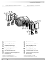
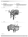
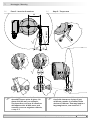
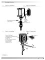
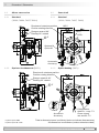
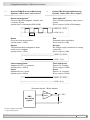
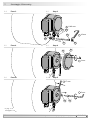
4.2 Ambito di fornitura della morsettiera 4.2 Scope of delivery terminal box
11a
Coperchio della morsettiera
11b
Vite combi Torx M4x32 mm
11c
Pressacavo M20x1,5 mm
per diametri del cavo 5…13 mm
11d
Piastra di collegamento,
v. cap. 5.12 e 7.3.
11e
Vite combi Torx M3x10 mm
11f
Connettore D-SUB sull‘alloggiamento
dell‘apparecchio
1)
Opzione G: encoder doppio HOG 10 G
2)
Opzione M: scansione ridondante HOG 10 M
11a
Terminal box cover
11b
Torx/slotted screw M4x32 mm
11c
Cable gland M20x1.5 mm
for cable ø5...13 mm
11d
Connecting board,
see section 5.12 and 7.3.
11e
Torx/slotted screw M3x10 mm
11f
D-SUB connector (male) on the
device housing
1)
Option G: Twin encoder HOG 10 G
2)
Option M: Redundant sensing HOG 10 M
11a
11a
11a
11f
11f
11f
11c
11a
11e 11d
11f
1) 2)
2)
1)
-
-
-
11b

9
Baumer_HOG10-HOG10G_T2_DE_EN_202010_MI_ (20A3)
MB071T2IT
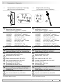
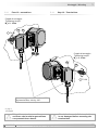
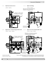
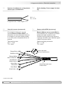
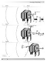
4 Preparazione / Preparation
4.3 Componenti necessari per il montag-
gio (non inclusi nella dotazione)
4.3 Required for mounting
(not included in scope of delivery)
16
18a
18e
18d
18b
18c
19a
19b
17
3x
3x
18
19
L
16
Braccio di reazione,
disponibile come accessorio:
codice da ordinare
lunghezza L, versione
11043628 67...70 mm, standard
11004078 125 (±5) mm
4)
, standard
11002915 440 (+20/-15) mm
5)
, standard
11054917 67...70 mm, isolato
11072795 125 (±5) mm
4)
, isolato
11082677 440 (+20/-15) mm
5)
, isolato
11054918 67...70 mm, inox
11072787 125 (±5) mm
4)
, inox
11072737 440 (+20/-15) mm
5)
, inox
17
Cavo del sensore HEK 8,
disponibile come accessorio, v. cap. 7.6.
18
Set montaggio disponibile come accessorio:
codice da ordinare 11077197, composto da ...
18a
Asta lettata M6 (1.4104),
lunghezza variabile (≤210 mm)
18b
Rondella B6,4, ISO 7090
18c
Dado autobloccante M6, ISO 10511
18d
Vite cilindrica M6x8 mm, ISO 1207
per bandella di messa a terra
18e
Rondella B6,4, ISO 7090
per bandella di messa a terra
19
Set montaggio/smontaggio disponibile come
accessorio: codice da ordinare 11077087,
composto da ...
19a
Rondella elastica 6, DIN 7980
19b
Vite cilindrica M6x30 mm, ISO 4762
4)
Può essere ridotto a ≥71 mm
5)
Può essere ridotto a ≥131 mm
16
Torque arm,
available as accessory:
Order number Length L, version
11043628 67...70 mm, standard
11004078 125 (±5) mm
4)
, standard
11002915 440 (+20/-15) mm
5)
, standard
11054917 67...70 mm, insulated
11072795 125 (±5) mm
4)
, insulated
11082677 440 (+20/-15) mm
5)
, insulated
11054918 67...70 mm, stainless
11072787 125 (±5) mm
4)
, stainless
11072737 440 (+20/-15) mm
5)
, stainless
17
Sensor cable HEK 8,
available as accessory, see section 7.6.
18
Mounting kit available as accessory:
Order number 11077197, including ...
18a
Thread rod M6 (1.4104),
lengthvariable(≤210mm)
18b
Washer B6.4, ISO 7090
18c
Self-locking nut M6, ISO 10511
18d
Cylinder screw M6x8 mm, ISO 1207
for earthing strap
18e
Washer B6.4, ISO 7090
for earthing strap
19
Mounting/dismounting kit available as
accessory:
Order number 11077087, including ...
19a
Spring washer 6, DIN 7980
19b
Cylinder screw M6x30 mm, ISO 4762
4)
Canbeshortenedto≥71mm
5)
Canbeshortenedto≥131mm

MB071T2IT
Baumer_HOG10-HOG10G_T2_DE_EN_202010_MI_ (20A3)
10
Preparazione / Preparation 4
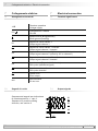
19
Set montaggio/smontaggio disponibile come
accessorio: codice da ordinare 11077087,
composto da ...
19c
Vite senza testa M6x10 mm, ISO 7436
19d
Vite cilindrica M8x45 mm, ISO 4762
19
Mounting/dismounting kit available as
accessory:
Order number 11077087, including ...
18c
Setscrew M6x10 mm, ISO 7436
19d
Cylinder screw M8x45 mm, ISO 4762
4.4 Componenti necessari per lo smontag-
gio (non inclusi nella dotazione)
4.4 Required for dismounting
(not included in scope of delivery)
4.5 Strumenti necessari
(non inclusi nella dotazione)
4.5 Required tools
(not included in scope of delivery)
19
19c 19d
3, 5 e 6 mm
1,6x8,0 mm e 0,8x4 mm
10 (2x), 17 e 22 mm
TX 10, TX 20
20
Set strumenti disponibile come accessorio:
codice da ordinare 11068265
3, 5 and 6 mm
1.6x8.0 mm and 0.8x4 mm
10 (2x), 17 and 22 mm
TX 10, TX 20
20
Tool kit available as accessory:
Order number 11068265

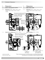
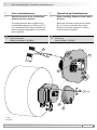
5 Montaggio / Mounting
11
Baumer_HOG10-HOG10G_T2_DE_EN_202010_MI_ (20A3)
MB071T2IT
5.2 Fase 2 5.2 Step 2
5 Montaggio
Le immagini mostrano il modello HOG
10 standard. Le fasi di montaggio sono
identiche per tutte le altre versioni.
5.1 Fase 1
5 Mounting
Pictures showing the standard HOG 10
as example. Same mounting steps for all
versions.
5.1 Step 1
16
*
7 6
*
* *
89
**
* V. pag. 7 o 9
See page 7 or 9
5
10 mm
10 mm
3 mm

MB071T2IT
Baumer_HOG10-HOG10G_T2_DE_EN_202010_MI_ (20A3)
12
Montaggio / Mounting 5
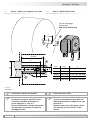
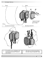
5.3 Fase 3 - albero cavo aperto su un lato 5.3 Step 3 - Blind hollow shaft
Lubricare l‘albero del motore. Lubricate drive shaft.
L‘albero motore deve avere un errore
di rotazione minimo, perché in caso
contrario potrebbe vericarsi un
errore angolare, v. cap. 5.7.
Errore di rotazione causano vibrazioni
che possono accorciare la vita utile
dell‘apparecchio.
The drive shaft should have as less
runout as possible because this can
otherwise result in an angle error, see
section 5.7.
Runouts can cause vibrations, which
can shorten the service life of the
device.
L
ød
h6
Foro di centraggio
Center hole
DIN 332-D, M6x16 mm
3
*
M6
ød1
ød
h6
L
53 mm
(35 mm con/at ød = 19, 20 mm)
16 mm
3
2
*
*
* V. pag. 7
See page 7
ød
h6
ød1 L
12 mm ≥ ø15 mm 52 mm (40...52 mm)
15 mm ≥ ø19 mm 52 mm (40...52 mm)
16 mm ≥ ø20 mm 52 mm (40...52 mm)
19 mm ≥ ø24 mm 34 mm (25...34 mm)
20 mm ≥ ø25 mm 34 mm (25...34 mm)

5 Montaggio / Mounting
13
Baumer_HOG10-HOG10G_T2_DE_EN_202010_MI_ (20A3)
MB071T2IT
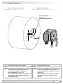
5.4 Step 3 - Cone shaft 5.4 Fase 3 - albero cavo conico
20 mm
1:10
Foro di centraggio
Center hole
DIN 332-D, M6x16 mm
ø17
JS8
mm
Lubricare l‘albero del motore. Lubricate drive shaft.
L‘albero motore deve avere un errore
di rotazione minimo, perché in caso
contrario potrebbe vericarsi un
errore angolare, v. cap. 5.7.
Errore di rotazione causano vibrazioni
che possono accorciare la vita utile
dell‘apparecchio.
The drive shaft should have as less
runout as possible because this can
otherwise result in an angle error, see
section 5.7.
Runouts can cause vibrations, which
can shorten the service life of the
device.

MB071T2IT
Baumer_HOG10-HOG10G_T2_DE_EN_202010_MI_ (20A3)
14
Montaggio / Mounting 5
5.5 Fase 4 5.5 Step 4
Coppia di serraggio
albero cavo aperto su un lato:
Tightening torque
blind hollow shaft:
M
t
= 6 Nm
Coppia di serraggio
albero cavo conico:
Tightening torque
cone shaft:
M
t
= 3...4 Nm
19b19a
18a
18e
18b 18b
16
21b
18c18b
18d
**
*
* *
*
*
**
*
* V. pag. 9
See page 9
18c
*
17 mm
5 mm
10 mm
1.6x8 mm

5 Montaggio / Mounting
15
Baumer_HOG10-HOG10G_T2_DE_EN_202010_MI_ (20A3)
MB071T2IT
5.6 Fase 5 - braccio di reazione 5.6 Step 5 - Torque arm
15°
15°
9°
9°
9°
9°
L1
L2 (≥L1)
Il montaggio del braccio di reazione
dovrebbe essere privo di gioco. Un
gioco di ±0,03 mm, per esempio,
corrisponde a un errore di rotazione
dell‘apparecchio di 0,06 mm e può
causare un errore angolare notevole,
v. cap. 5.7.
The torque arm should be mounted
free from clearance. A play of just
±0.03 mm, results in a runout of the
device of 0.06 mm. That may lead to a
large angle error, see section 5.7.

MB071T2IT
Baumer_HOG10-HOG10G_T2_DE_EN_202010_MI_ (20A3)
16
Montaggio / Mounting 5
5.7 Indicazioni per evitare errori di misura-
zione
Per assicurare un perfetto funzionamento
dell‘apparecchio è necessario montare
correttamente quest‘ultimo, e soprattutto il
braccio di reazione, secondo le indicazio-
ni riportate ai cap. 5.1 a 5.6.
L‘errore di rotazione massima dell‘albero
motore non dovrebbe possibilmente su-
perare 0,2 mm (0,03 mm consigliati), per
evitare un errore angolare.
Tale errore angolare può essere ridotto
aumentando la lunghezza di L1
6)
. Si deve
assicurare, che la lunghezza L2 del brac-
cio di reazione, v. cap. 5,6, sia almeno
pari alla lunghezza di L1
7)
.
L‘errore angolare può essere calcolato
come segue:
Δρ
mecc
= ± 90°/π · R/L1
con R:
errore di rotazione in mm
L1:
Distanza del braccio di reazione dal punto
centrale dell‘apparecchio in mm
Esempio di calcolo:
Per R = 0,06 mm e L1 = 69,5 mm l‘errore
angolare calcolato
Δρ
mecc
è pari a ± 0,025°.
i
Per ulteriori informazioni, chiamare
ll‘assistenza al numero
+49 (0)30 69003-111
5.7 How to prevent measurement errors
To ensure that the device operates cor-
rectly, it is necessary to mount it accu-
rately as described in section 5.1 to 5.6,
which includes correct mounting of the
torque arm.
The radial runout of the drive shaft should
not exceed 0.2 mm (0.03 mm recom-
mended), if at all possible, to prevent an
angle error.
An angle error may be reduced by
increasing the length of L1
6)
. Make sure
that the length L2 of the torque arm, see
section 5.6, is at least equal to L1
7)
.
The angle error can be calculated as
follows:
Δρ
mech
= ± 90°/π · R/L1
with R:
Radial runout in mm
L1:
Distance of the torque arm to the center
point of the device in mm
Example of calculation:
For R = 0.06 mm and L1 = 69.5 mm the
resulting angle error
Δρ
mech
equals ± 0.025°.
i
For more information,
call the telephone hotline at
+49 (0)30 69003 -111
6)
Sono disponibili su richiesta diverse piastre di supporto per i
bracci di reazione.
7)
Se L2<L1, si deve calcolare con la lunghezza di L2.
6)
For this different support plates for the torque arm are
available on request.
7)
If L2 < L1, L2 must be used in the calculation formula.

5 Montaggio / Mounting
17
Baumer_HOG10-HOG10G_T2_DE_EN_202010_MI_ (20A3)
MB071T2IT
5.9 Istruzioni di montaggio 5.9 Mounting instruction
5.8 Fase 6 5.8 Step 6
98
**
* V. pag. 7
See page 7
Coppia di serraggio:
Tightening torque:
M
t
= 2...3 Nm
i
Si consiglia di montare l‘apparecchio
in modo tale, che il collegamento del
cavo non lasci penetrare l‘acqua in
modo diretto.
i
It is recommended to mount the device
with cable connection facing down-
ward and being not exposed to water.
3 mm
La pagina si sta caricando...
La pagina si sta caricando...
La pagina si sta caricando...
La pagina si sta caricando...
La pagina si sta caricando...
La pagina si sta caricando...
La pagina si sta caricando...
La pagina si sta caricando...
La pagina si sta caricando...
La pagina si sta caricando...
La pagina si sta caricando...
La pagina si sta caricando...
La pagina si sta caricando...
La pagina si sta caricando...
La pagina si sta caricando...
La pagina si sta caricando...
La pagina si sta caricando...
La pagina si sta caricando...
La pagina si sta caricando...
La pagina si sta caricando...
-
 1
1
-
 2
2
-
 3
3
-
 4
4
-
 5
5
-
 6
6
-
 7
7
-
 8
8
-
 9
9
-
 10
10
-
 11
11
-
 12
12
-
 13
13
-
 14
14
-
 15
15
-
 16
16
-
 17
17
-
 18
18
-
 19
19
-
 20
20
-
 21
21
-
 22
22
-
 23
23
-
 24
24
-
 25
25
-
 26
26
-
 27
27
-
 28
28
-
 29
29
-
 30
30
-
 31
31
-
 32
32
-
 33
33
-
 34
34
-
 35
35
-
 36
36
-
 37
37
-
 38
38
-
 39
39
-
 40
40


Baumer HOG 10 Installation and Operating Instructions
- Tipo
- Installation and Operating Instructions
- Questo manuale è adatto anche per
in altre lingue
- English: Baumer HOG 10
Documenti correlati
Altri documenti
-
Campomatic RB2200 Manuale del proprietario
-
AmazonCommercial B09DD8L8LD Manuale utente
-
Audio System HTL 202 Manuale utente
-
Renkforce LV-BH Manuale del proprietario
-
Lika IF10 Manuale utente
-
ABB FEN-01 Quick Manual
-
Videotec MAXIMUS MBX Manuale utente
-
-
Kollmorgen C05 Manuale utente
-