
GCE CUTTING & WELDING TECHNOLOGIES
INSTRUCTION FOR USE :
STRAIGHT LINE PORTABLE CUTTING MACHINE
BEDIENUNGSANLEITUNG : TRAGBARE BRENNSCHNEIDMASCHINE
FÜR GERADES BRENNSCHNEIDEN
EN
DE
NÁVOD K POUŽITÍ :
PŘENOSNÝ ŘEZACÍ STROJ PRO PŘÍMÉ ŘEZÁNÍ KYSLÍKEM
MODE D’EMPLOI :
MACHINE D’OXYCOUPAGE DROITE PORTABLE
CS
FR
MANUALE D´USO : MACCHINA DA TAGLIO PORTATILE
PER TAGLIO DIRETTO AD OSSIGENO
INSTRUCCIONES DE USO : MÁQUINA PORTÁTIL
DE CORTE TRANSVERSAL CON OXÍGENO
IT
ES
INSTRUÇÕES DE USO : MÁQUINA CORTADORA PORTÁTIL
PARA CORTE RECTO A OXIGÉNIO
BRUKSANVISNING : PORTABEL SKÄRMASKIN
FÖR RÄTLINJIG SKÄRNING MED OXYFUEL
PT
SV
:
INSTRUKCJA OBSŁUGI : PRZENOŚNY PÓŁAUTOMAT
DO PROSTOLINIOWEGO CIĘCIA TLENEM
RU
PL
HASZNÁLATI ÚTMUTATÓ : HORDOZHATÓ LÁNGVÁGÓGÉP
OXIGÉNNEL TÖRTÉNŐ KÖZVETLEN VÁGÁSRA HU
SLM


EN
3/136
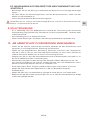
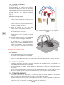
1. DESCRIPTION
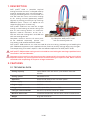
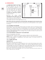
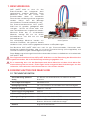
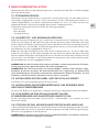
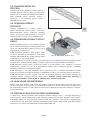
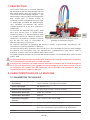
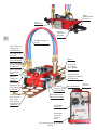
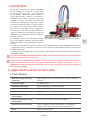
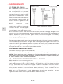
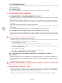
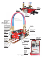
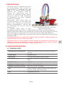
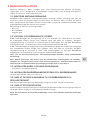
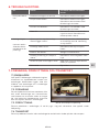
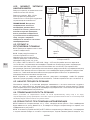
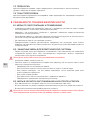
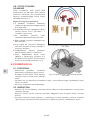
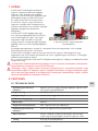
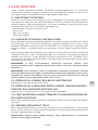
GCE proFIT® SLM is portable oxy-fuel
cutting machine that cuts unalloyed steel by
material combustion with using of oxygen –
fuel gas preheating flame. This machine can
also be used for linear and circular cutting
or for cutting curved (patterned) profiles
(figures) by moving manually or by installing
additional parts. There is an option to use
second cutting torch if necessary.
GCE proFIT® SLM can be used for straight
cutting, curved cutting or bevel cutting with
one or two cutting torches at maximum.
Maximal material thickness to be cut is
150mm with one cutting torch and 100mm
with two cutting torches.
Complete machine consists of more parts
to be ordered separately, please see
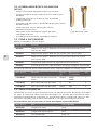
Fig.1 Machine GCE proFIT® SLM
with Zn-coated guide rail
instructions and recommendation below.
GCE proFIT® SLM machine can also be used for plasma cutting, preheating and welding but
with additional equipment (not supplied with the machine) and by making necessary changes.
These operating instructions explain safe and ecient operation of GCE proFIT® SLM .
GCE proFIT® SLM portable cutting machine should be used taking the warnings specified in the
instructions into consideration.
Operators of the machine shall have learnt the content of this Instruction for Use and shall be
experienced with oxy-fuel equipment and trained according to request of ISO, EN or national
standards with respecting all requests of legal authorities.
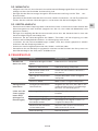
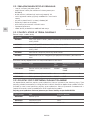
2. FEATURES
2.1. TECHNICAL DATA
Cutting capacity up to 150mm with one torch, up to 100mm with two
torches
Cutting speed 50-1600mm/min
Operation forward and reverse with variable speed
Power supply 230V AC / 110V AC
Engine supply 24V DC
Oxygen inlet connection G1/4“, up to 8bar, hose min. DN6
Fuel gas inlet connection G3/8“LH, up to 1bar, hose min. DN8
Machine dimensions 175x350x140 (WxLxH) without torch, hoses and torch bar
Weight 9kg with one torch

EN
4/136
2.2. BASIC MACHINE PACKAGE INCLUDES:
• equipment for one torch-cutting application
• one nozzle-mix cutting torch (only for 0870613)
• torch holder, torch bar, heat shield
• internal gas hoses, gas manifold with shut-o valves
• circle cutting pole, circle centre-piece
• electric cable with plug
• nozzle mounting and cleaning accessories
• flame lighter
• guide rail is delivered separately from the machine
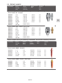
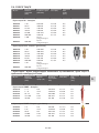
2.3. ITEMS TO BE ORDERED
Cutting machines and guiding rail-tracks
Art number Description
0870613 GCE proFIT® SLM machine with one nozzle mix torch, without track,
230V
0870614 GCE proFIT® SLM machine without torch, without track, 230V
0870615 GCE proFIT SLM machine with one nozzle mix torch, without track, 110V
0870616 Extension kit for second cutting torch
0870617 Guide rail track 1,8 m, Zn/coated steel
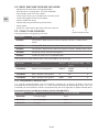
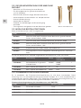
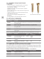
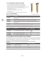
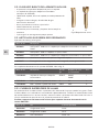
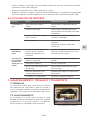
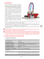
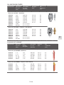
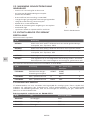
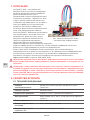
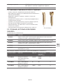
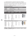
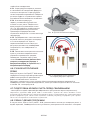
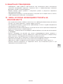
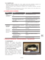
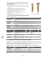
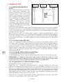
Cutting torches to be ordered with machine 0870614, see also Fig.2:
Art number Description Gas type Recomended cutting
nozzles
Pos.
F25310014 Nozzle mix cutting torch APMYF ANME
PNME
1
F25310013 BIR+, injector cutting torch A AC 2
F25310012 BIR+, injector cutting torch PMYF PUZ 2
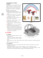
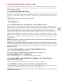
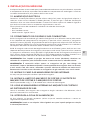
2.3.1. FLASHBACK ARRESTORS
It is strongly recommended using of flashback arrestors for all gases. Arrestors are to be
mounted at the cutting torch inlets. It is also recommended and according to local rules also
mandatory to use flashback arrestors mounted at the pressure regulator or pipeline outlet point.
Flashback Arrestors for Machine Cutting Torches EN ISO 5175-1
Art number Gas Connection (EN 560)
14008408 Cutting oxygen G3/8”
14008263 Heating oxygen G1/4”
14008278 Fuel gas G3/8” LH
Fig.2 Cutting torches
1 2

EN
5/136
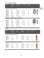
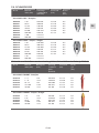
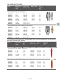
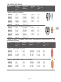
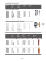
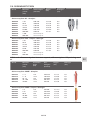
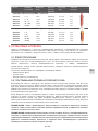
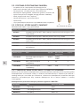
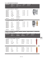
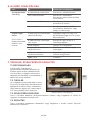
2.4. CUTTING NOZZLES
Art. Nr. Cutting
thickness
(mm)
Cutting speed
(mm/min)
Oxygen (bar) Fuel gas
(bar)
Cutting nozzles AC - Acetylene
14001010
14001011
14001012
14001013
14001014
14001015
14001020
14001021
3-10
10-25
25-40
40-60
60-100
100-200
3-100
100-300
600-730
410-620
340-410
310-340
250-320
210-270
Heating nozzle
Heating nozzle
2,0-3,0
4,5-5,0
4,0-5,0
4,0-5,0
5,0-6,0
6,5-7,5
0,5
0,5
0,5
0,5
0,5
0,5
Cutting nozzles PUZ - Propane / Natural Gas
14001350
14001351
14001352
14001353
14001354
14001355
14001147
14001148
3-10
10-25
25-40
40-60
60-10
100-200
3-10
100-300
550-600
400-560
350-400
310-340
260-310
180-260
Heating nozzle
Heating nozzle
2,0-3,0
4,5-5,0
4,0-5,0
4,5-5,5
5,0-6,0
5,5-6,5
0,2
0,2
0,2
0,2
0,2
0,3
* Cutting and heating nozzles are delivered separately, cutting nozzles in the 5 pcs
package.
Art. Nr. Cutting
thickness
(mm)
Nozzle size
(inch)
Cutting
speed
(mm/min)
Oxygen (bar) Fuel gas
(bar)
Cutting nozzles ANME - Acetylene
0768670
0768635
0768599
0768636
0768662
3 - 6
5 - 12
10 - 75
70 - 100
90-150
1/32
3/64
1/16
5/64
3/32
470-560
390-480
205-400
150-220
125-160
2,5-3,5
2,0-4,0
3,5-4,5
4,5-5,5
5,5-6,0
0,3
0,3
0,3
0,5
0,5
Cutting nozzles PNME - Propane / Natural Gas
0769494
0769495
0769496
0769497
0769498
3-6
5-12
10-75
70-100
90-150
1/32
3/64
1/16
5/64
3/32
430-150
360-440
205-380
150-220
125-160
2,5--3,5
3,0-4,0
3,5-4,5
4,5-5,5
5,5-6,5
0,2
0,2
0,2
0,4
0,4

EN
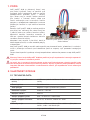
6/136
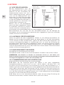
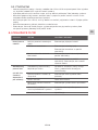
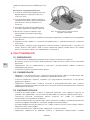
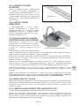
Forward-
backward
movement
control
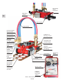
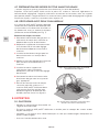
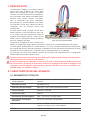
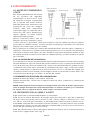
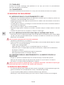
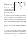
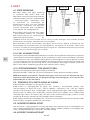
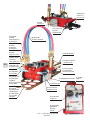
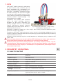
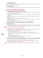
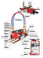
Fig.3: Machine description
Heating oxygen
shut-o valve
Oxygen inlet
connection:
G1/4
Internal gas hoses
Guiding
rail track
Cutting torch
with the rack
Cutting oxygen
shut-o valve
Fuel gas
shut-o valve
Fuel gas inlet
connection:
G3/8 LH
Distance
adjustment
bar
Distance
adjustment
bar set-up
handwheel
Distance adjust-
ment bar fixing
handwheel
Torch height
adjustment
handwheel
Cutting nozzle
Cutting angle
handwheel
Heat shield
Castor wheel
for manual
steering
Machine
body
Power
cable
with plug
Clutch
lever
Speed control

EN
7/136
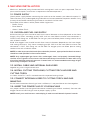
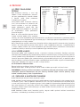
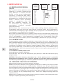
3. MACHINE INSTALLATION
Machine is delivered partly dismounted with cutting torch and arm parts separated. Take all
parts out of the pack. Install them in sequence as below to operate it.
3.1. POWER SUPPLY
Check power supply before connecting the machine to the network (see above the point 2.1.
Technical data). Only undamaged plug and cable can be connected to the power network. Only
the way of connection conforming to national standards shall be used.
Description of the colours of the power cable single wires:
• Brown: Phase
• Blue: Neutral
• Green / Yellow: Earth
3.2. OXYGEN AND FUEL GAS SUPPLY
3.2.1. Inlet fuel gas hose should be with 8mm internal diameter at least (depends on the hose
length). Only hoses according to ISO 3821 shall be used. Machine hose inlet connection is
G3/8”LH with fitting acc. to EN 560. For fuel gas pressure follow please cutting nozzles chart
with all details above.
3.2.2. Inlet oxygen hose should be with 6mm internal diameter (depends on the hose length
and cutting thickness). Only hoses according to ISO 3821 shall be used. Machine hose inlet
connection is G1/4” with fitting acc. to EN 560. For oxygen pressure follow please cutting
nozzles chart with all details above.
NOTE: In order to prevent flashback (flame backfire) hazards, appropriate flashback arrestors
should be used specified in Accessories below.
NOTE: Only undamaged gas hoses with undamaged, clean and properly fastened fittings
shall be used. Tightness of the hoses shall be tested every three months at latest with using
of maximal working pneumatic pressure in water bath. It is recommended to exchange all gas
hoses every three years at latest.
3.3. INSTALL CABLE AND INTERNAL GAS HOSES
together e.g. with using of hose brace.
3.4. INSTALL CUTTING TORCH BAR, CUTTING TORCH HOLDER AND
CUTTING TORCH
as shown at the Pic. 3 to 5 in accordance with requested cutting shape.
3.5. CONNECT INTERNAL HOSES TO CUTTING TORCH AND GAS
MANIFOLD.
As the hose connection of each gas hose is dierent, it’s not possible to mix them together.
3.6. INSERT THE POWER PLUG OF YOUR MACHINE
to a proper socket (use the type of connection according to national standard). Connect inlet
oxygen hose and inlet fuel gas hose to proper supply system.
NOTE: Install your machine to an earthed plug in order to avoid electrical power hazards.

EN
8/136
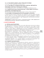
4. OPERATION
4.1. BEFORE START CUTTING
4.1.1. The operator shall be aware
of safe operation specified in this
Instruction for Use before any handling
with GCE proFIT® SLM. The operator
shall be experienced with oxy-fuel
equipment and trained according
to request of ISO, EN or national
standards with respecting all requests
of legal authorities.
4.1.2. Only the cutting nozzle
according to chart above shall be
used. Nozzle-mix/injector type of the
cutting torch has to be respected as
well as type of the fuel gas. Use only
undamaged nozzle with undamaged and clean seat.
4.1.3. Please check also cutting torch head seat before mounting the nozzle into the cutting
torch head. Only cutting torch from the list above with undamaged and clean nozzle seat can
be used. Nozzle-mix/injector type of the cutting torch has to be respected as well as type of
the fuel gas.
4.1.4. NOZZLE CHOOSING
Please follow the chart with cutting nozzles above. Use proper nozzle size according to metal
plate thickness. GCE cutting nozzles are designed for cuts of quality level 1 according to EN
ISO 9013. It is possible to reach maximal cutting speed by set-up cutting parameters according
to chart above, cutting of straight cuts, by using of clean metal sheet surface, quality cutting
machine, undamaged cutting nozzle and oxygen with purity 99,5% or better. Gas pressures are
measured at the torch inlet.
4.1.5.TIGHTENING TORQUE OF THE NOZZLES:
Nozzle-mix cutting torch: 22-30 Nm
Cutting torch BIR+: 12 Nm for inner cutting nozzle and 18Nm for outer heating nozzle.
NOTE: All parts in contact with oxygen should be free of oil and grease due to explosion
hazards! Check whether all threaded joints and sealing surfaces, e. g. cones and balls, are
clean and undamaged!
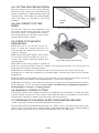
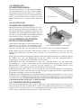
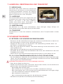
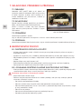
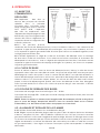
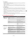
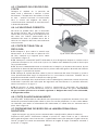
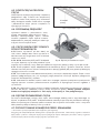
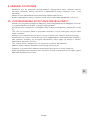
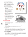
4.2. FLAME IGNITION
AND SET UP
4.2.1. Check all gas connection tightness.
4.2.2. Adjust inlet gas pressures according to the values in the table of cutting nozzles above,
see point 2.4. (1 bar = 1,05 kPa 100kPa = 105 N/m2, 1 bar = 14,5 psi). Open the fuel gas valve and
heating oxygen valve. Ignite the outgoing mixture with proper lighter (Do not use hot metal or
matchstick). With correct pressure adjustment is produced carburizing flame. A neutral heating
flame is to be adjusted with the fuel gas valve to suit the cutting task.
4.2.3. Open shortly the cutting oxygen valve to see correct adjustment of neutral flame and
close it afterwards (see also Fig.4).
Fig.4: Flame adjustment
Carburazing flame
during igniting
Neutral flame Neutral flame with
cutting oxygen jet
approx. 1mm
Workpiece

EN
9/136
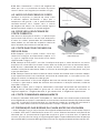
4.3. CUTTING PROCESS INITIATION
Bring the torch to the initial cutting position
and start locally heating the workpiece to the
ignition temperature, approximately bright red
/ yellow colour. Then open the cutting oxygen
valve and switch on the feed in the same
moment.
4.4. THE CORRECT CUTTING
SPEED
can be seen from the slag production, from
the almost vertical spray of sparks and from
the cutting noise. The approximate values of
the cutting speed can be taken from relevant
cutting nozzle table as above.
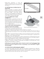
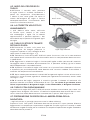
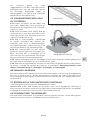
4.5. STRIPS CUTTING WITH
GUIDING RAIL
4.5.1. Place the rail on the part to be cut. If
there is a need for a length more than 1,8m
then connect the second rail with the first as
shown on Figure 5.
4.5.2. Place GCE proFIT® SLM on the rail. Make
sure that front and rear wheels fit in the rail
furrows. Rear wheel should be fixed to avoid
side movement.
4.5.3. Adjust the cutting speed in relation to
particular nozzle and material thickness. Adjust also movement direction. Turn clutch lever to
the direction of arrow to stand-by position.
4.5.4. Set the cutting torch on the metal sheet at the place of cut start. Ignite and set pre-
heating flame as required according to instruction above. Preheat the material on the ignition
temperature.
4.5.5. Fully open cutting oxygen valve in the same time and start moving machine by switching
of movement control knob in requested direction as shown on the Figure 3.
4.5.6. After the cutting is over, stop the machine by bringing the movement control switch in
central position, shut all the gases of. Gas valves shall be closed in following sequence: 1.
cutting oxygen, 2. fuel gas, 3. heating oxygen.
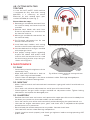
4.6. MANUALLY GUIDED CUTTING
GCE proFIT® SLM can be guided manually by the operator for free pattern cut over the outer
line of the pattern to be cut. Castor wheel is to be adjusted free for all directions and all of the
three wheels should be in contact with the panel. See also Figure 6.
4.7. PREPARING OF THE METAL SHEET EDGES BEFORE WELDING
– level cutting with one torch (without weld root face creation).
Prepare GCE proFIT® SLM according to point 4.5. above. Lose a bit the Cutting angle hand-
wheel and turn the torch with the torch holder to get requested angle. Then tighten properly
again Cutting angle hand-wheel. Proceed according to point 4.5. afterwards
Fig.6: Manually guided cutting
Fig.5: Zn coated track extension
Straight
edge

EN
10/136
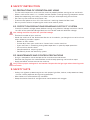
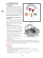
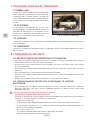
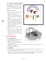
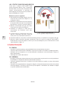
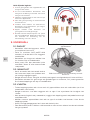
4.8. CUTTING WITH TWO
TORCHES
In case the GCE proFIT® SLM machine
is equipped for only one torch cutting
operation, it is necessary to mount
Extension kit with second torch (part
number 0870616) first (see Fig. 7).
Please follow the steps:
1. Remove gas manifold for one torch from
the machine body and hoses from the
manifold.
2. Remove torch holder with torch from
Distance adjustment bar and take the
bar from the machine.
3. Mount gas manifold for two torches on
the machine body.
4. Put Distance adjustment bar for two
torches into the machine.
5. Install both torch holders with cutting
torches at the Distance adjustment bar.
6. Connect both torches and gas manifold
with proper gas hoses.
7. Use proper cutting nozzles according
to point 2.4 above. GCE proFIT® SLM
machine with two torches can be used
for bevel cutting and for strip cutting as
shown at the Figure 8.
5. MAINTENANCE
5.1. DAILY
• Continuously check the tightness of the
nozzle-torch seat
• Wipe GCE proFIT® SLM with a cloth to
clean it from slag and metal oxides.
• Check if there are damages in the hoses and electric cable. Exchange damaged parts.
• Lubricate the spindle of rotating wheel.
5.2. MONTHLY
• Make sure that vertical and horizontal torch movement is going well and all hand wheels are
functional.
• Clean torch rack, distance adjustment bar and all parts of the torch holder.
• Check tightness the gas hoses and gas manifold incl. adjustment valves. Tighten leaking
connections and replace the damaged parts.
5.3. QUARTERLY
• Remove the clutch lever and screws and separate the upper part of the machine body from
the lower part. (make sure that motor cables are not stretched).
• Clean the interior parts of the machine carefully without damaging the speed control unit.
• Lubricate the engine connection parts, gears and clutch with a molybdenum-disulphide
based lubricant as a precaution.
• Reinstall body lids without compression any cables. Connect clutch lever.
• Lubricate front and rear wheel bearings components.
• Check if machine works properly and check gas tightness before starting operating GCE
proFIT® SLM.
Fig.7: Extension kit with second cutting torch
Fig.8: Bevel cutting and strip cutting with two
torches

EN
11/136
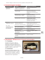
6. TROUBLE SHOOTING
Failure Cause Repair
Drive
wheel does not
turn
Cable connections are loose Check the solder of the cables.
Defective commutator Check the cable connection.
Check the commutator with a
test device.
Failure of the main electric cable Check the main electric cable
with a test device.
Defective motor Check it with a test device.
Check if the motor spindle
rotates.
Ragged
Cutting
Surface
(see also adjust-
ment recommen-
dation below)
A ragged surface
Unfitting rail
Make sure that the surface to be
cut is smooth enough for the
rail to fit
Rotating speed of the motor is
wrong
Check or replace the control
units.
External vibration Stop vibrations
Wrong cutting parameters
adjustments
Check the speed of cutting with
the ruler.
Abnormal delays in propulsion
gear component
Repair it or get it repaired.
Distortion of the torch Replace it.
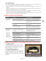
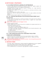
7. STORAGE, CARRYING AND TRANSPORTATION
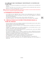
7.1. PACKING
GCE proFIT® SLM is surrounded by preser-
vations all around the box. Cutting machine
body is in the box separated from the ac-
cessories; the box is divided into two parts.
7.2. STORAGE
If the cutting machine is not going to be
used for a long time, keep the electric
components, torch and nozzles in the box to
protect them from dust, humidity and other
impurities.
7.3. CARRYING
Keep the product in the box to prevent
failures arising from shocks and vibrations during carrying.
7.4. TRANSPORTATION
Keep the product properly in its box to prevent it from damages during transportation. Storage,
carrying and transportation
Fig 9. An example of packing

EN
12/136
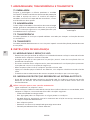
8. SAFETY INSTRUCTION
8.1. PRECAUTIONS OF OPERATION AND USING
• Fix the machine position and install the machine properly before starting to use and check.
• Make sure that the switch is in “middle” position before inserting the plug into power socket.
• Keep these operating and safety instructions with you when operating the machine.
• Do not carry the machine while flame is on.
• Prevent metal pieces or burr fall if the machine is working above the floor level.
• Be very careful when transporting the machine to another place.
8.2. PROTECTION PRECAUTIONS REGARDING ELECTRICITY SYSTEM
• Check the network voltage power before starting using. Maximal voltage variations should
be ±10% of the specified voltage. Machine shall not be used with dierent voltage.
Use cutting machine only with the specified voltage.
• Earthen the cable of your machine.
• Send the machine to the Authorized Service or the dealer you bought the machine from
when following situation happen:
• Broken or worn cables.
• If water drips from your machine or if water leaks into the machine.
• If you see there is something wrong about operation in spite of proper operation.
• If the machine breaks down.
• Complicated fault requiring repair.
• Periodically check the electricity system.
8.3. MAINTENANCE AND CONTROL PRECAUTIONS
• Assign a competent authorized person for maintenance and control.
• Remove the plug from the socket before machine body opening and machine repair.
• Apply periodical maintenance to the machine.
Only use the proper cutting torch and nozzles. Respect the fuel gas type when choosing torch
and nozzle.
9. SAFETY SUITS
• Safety suits (gloves, protective glasses with proper light filter, helmet, and protective shoes)
shall be used by operator during cutting operation.
• Wet clothes can lead to electricity accidents.
• Keep the clothes free of oil and grease to avoid reaction with oxygen

EN
13/136
10. PRECAUTIONS WHICH SHALL BE TAKEN IN WORKING
AREA
• Keep the flame away from the gas source, keep at least 3m safety distance (gas cylinders,
pipeline, and hoses)
• Do not expose acetylene cylinder, pipeline, hoses and tubes to temperatures higher than
50°C (130°F).
• Oxygen does not catch fire by itself, however in case of contact with another flammable
material it easily catches fire.
• Make sure that rate of oxygen within the working area is not higher than the rate in
atmosphere.
• Flame forming as a result of contact of oxygen with lubricant, grease or other hydro-carbons
lead to fire and explosions. Keep all components which can be in touch with oxygen free
from oil and grease.
• Oxygen, propane, propylene and their mixtures are heavier than air.
• Ventilate the working room suciently during cutting.
• Keep fire extinguisher, sand, water, etc. available in working area.
• Keep flammable materials away from the location of cutting and from the sparks.

EN
14/136
Adjustment Recommendation for Perfect Machine Cutting
Narrowing of kerf (divergent)
• Forward speed of torch
too fast
• Distance between nozzle
and sheet metal too big
• Dirty and / or damaged
nozzle
Narrowing of kerf (conver-
gent)
• Forward speed of torch
too fast
• Distance between nozzle
and sheet metal too big
• Cutting oxygen pressure
too high
Concave cut surface beneath
top edge
• Cutting oxygen pressure
too high
• Dirty and / or damaged
nozzle
• Distance between nozzle
and sheet metal too big
Step at bottom edge
• Forward speed of torch
too fast
• Dirty and / or damaged
nozzle
Concave cut surface profile
• Forward speed of torch
too fast
• Dirty and/or damaged noz-
zle or nozzle size too small
for the thickness to be cut
• Cutting oxygen pressure
too low
Irregular cut surface profile
• Cutting oxygen pressure
too low
• Dirty and / or damaged
nozzle
• Forward speed of torch
too fast
Edge melting on
• Forward speed of torch
too slow
• Heating flame too strong
• Distance between nozzle
and sheet metal too big to
too small
• Nozzle size too big for the
thickness to be cut
String of solidified droplets
• Heating flame too strong
• Distance between nozzle
and sheet metal too small
• Scaled or corroded sheet
metal surface
Melted down top edge
with adherent slag
• Cutting oxygen pressure
too high
• Heating flame too strong
• Distance between nozzle
and sheet metal too big
Lower edge rounded
• Cutting oxygen pressure
too high
• Forward speed of torch
too fast
• Dirty and / or damaged
nozzle
Excessive cut drag line depth
• Forward speed of torch too
fast or irregular
• Distance between nozzle
and sheet metal too small
• Heating flame too strong
Excessive cut drag line
depth
• Forward speed of torch too
fast or irregular
• Distance between nozzle
and sheet metal too small
• Heating flame too strong
Single gouges
• Forward speed of torch
too slow
• Scaled or corroded or dirty
sheet metal surface
• Distance between nozzle
and sheet metal too small
• Flame too weak
• Flame extinguished with
a ban
• Sheet metal with finely
divided inclusions
Grouped gouge areas
• Forward speed of torch
too fast
• Scaled or corroded or dirty
shee metal surface
• Distance between nozzle
and sheet metal too small
• Flame too weak
Grouped gouges in the bot-
tom half of the cut
• Forward speed of torch
too slow
• Dirty and / or damaged
nozzle
Firmly adherent slag line
ad bottom edge
• Forward speed of torch
too fast or too slow
• Distance between
nozzle and sheet metal
too big
• Cutting oxygen pressure
too low
• Nozzle size too small for
the thickness to be cut
• Flame too weak
• Scaled or corroded or
dirty (colour) sheet metal
surface

DE
15/136
1. BESCHREIBUNG
GCE proFIT® SLM ist eine für das
Brennschneiden von unlegierten Stahl
vorgesehene, tragbare Maschine. Diese
Maschine kann für das Linear- und
Rundschneiden sowie für individuelle
Formschnitte und Schrägschnitte eingesetzt
werden. Hierzu kann die Montage
verschiedener Zusatzteile erforderlich sein.
Die Brennschneidmaschine GCE proFIT®
SLM kann für geraden, gebogenen oder
schrägen Schnitt mit einem oder max.
zwei Schneidbrennern angewandt werden.
Maximale Dicke des zu schneidenden
Materials beträgt 150 mm mit einem
Schneidbrenner und 100 mm mit zwei
Schneidbrennern.
Die vollständige Maschine besteht aus
mehreren Bauteilen, die getrennt bestellt
Bild 1 Maschine GCE proFIT® mit verzinkter
Führungsbahn
werden müssen; siehe unten angegebene Hinweise und Empfehlungen.
Die Maschine GCE proFIT® SLM kann auch für das Plasmaschneiden, Vorwärmen oder
Schweißen angewandt werden, aber nur mit einer Zusatzeinrichtung (nicht mitgeliefert) und
nach der Durchführung der notwendigen Anpassungen.
Diese Bedienungsanleitung erklärt die Grundsätze des sicheren und eektiven schinenbetriebs
GCE proFIT® SLM.
Die tragbare Schneidmaschine GCE proFIT® SLM kann nur bei Beachtung der Warnhinweise
angewandt werden, die in der Bedienungsanleitung angegeben sind.
Es ist notwendig, dass sich das Bedienpersonal dieser Maschine mit dem Inhalt dieser Be-
triebsnaleitung vertraut macht, Erfahrungen besitz und gemäß den Anforderungen aus den
nationalen, internationalen sowie firmeninternen Vorschriften handelt.
2. EIGENSCHAFTEN DER MASCHINE
2.1. TECHNISCHE DATEN
Schneidleistung (Material-
dicke);;
bis 150mm mit einem Brenner, bis 100mm mit zwei
Brennern
Schneidgeschwindigkeit 50-1600mm/min
Bewegungsrichtung vor- und rückwärts mit veränderlicher Geschwindigkeit
Stromversorgung 230V AC / 110V AC
Spannungsversorgung Motor 24V DC
Sauersto-Eingangsanschluss G1/4”, bis 8 bar, Schlauch DN6
Brenngas-Eingangsanschluss G3/8” LH, bis 1bar, Schlauch DN8
Maschinenmaße 175mm x 350mm x 140mm (Breite x Länge x Höhe) ohne
Brenner, Schläuche und Brennerstange
Gewicht 9kg mit einem Brenner

DE
16/136
2.2. DIE GRUNDVERPACKUNG DER MASCHINE
ENTHÄLT:
• Maschine inkl. Einrichtung für einen Brenner
• Ein Schneidbrenner für gasemischende Düsen
(nur für 0870613)
• Brennerhalter, Brennerstange, Wärmeschutzschild
• Schlauchpaket und Gasverteiler mit Absperrventilen
• Kreisschneideinrichtung
• Stromkabel mit Stecker
• Zubehör für die Montage und Düsenreinigung
• Anzünder
• Führungsbahn wird getrennt von der Maschine geliefert
2.3. MÖGLICHE BESTELLPOSITIONEN
Brennschneidmaschinen und Führungsbahnen
Art Nr. Beschreibung
0870613 Maschine GCE proFIT® SLM mit einem Brenner für gasemischende
Düsen, ohne Lauahn, 230V
0870614 Maschine GCE proFIT® SLM ohne Brenner, ohne Bahn, 230V
0870615 Maschine GCE proFIT® SLM mit einem Brenner für gasemischende
Düsen, ohne Lauahn, 110V
0870616 Erweiterungssatz für den zweiten Schneidbrenner
0870617 Führungsbahn 1,8 m mit integriertem Verbindungsschloss, verzinkter
Stahl
Für die mit der Maschine 0870614 mitgelieferten Schneidbrenner, siehe auch Bild 2:
Art Nr. Beschreibung Gastyp Empfohlene
Schneiddüsen
Pos.
F25310014 Schneidbrenner für gasemis-
chende Düsen
APMYF ANME
PNME
1
F25310013 BIR+, Injektor-Schneidbrenner A AC 2
F25310012 BIR+, Injektor-Schneidbrenner PMYF PUZ 2
2.3.1.FLAMMENRÜCKSCHLAGSICHERUNG
Es ist empfohlen, die Flammenrückschlagsicherung für alle Gase anzuwenden. Diese
Sicherung muss am Schneidbrennereingang montiert werden. Es ist auch empfehlenswert,
und gemäß den örtlichen Regelungen ist es notwendig, die Flammenrückschlagsicherung am
Druckminderer oder an der Rohrleitung-Entnahmestelle zu montieren.
Flammenrückschlagsicherung für Schneidbrenner nach EN 5175-1
Art Nr. Gas Anschluss (EN 560)
14008408 Sauersto schneiden G3/8”
14008263 Sauersto erhitzen G1/4”
14008278; Brenngas G3/8” LH
Bild 2 Schneidbrenner
1 2

DE
17/136
2.4. SCHNEIDDÜSE
Art. Nr. Material-
dicke (mm)
Schneidge-
schwindigkeit
(mm/min)
Sauersto
(bar)
Brenn-
gas
(bar)
Schneiddüse AC - Acetylen
14001010
14001011
14001012
14001013
14001014
14001015
14001020
14001021
3-10
10-25
25-40
40-60
60-100
100-200
3-100
100-300
600-730
410-620
340-410
310-340
250-320
210-270
Heizdüse
Heizdüse
2,0-3,0
4,5-5,0
4,0-5,0
4,0-5,0
5,0-6,0
6,5-7,5
0,5
0,5
0,5
0,5
0,5
0,5
Schneiddüse PUZ - Propan / Erdgas
14001350
14001351
14001352
14001353
14001354
14001355
14001147
14001148
3-10
10-25
25-40
40-60
60-10
100-200
3-10
100-300
550-600
400-560
350-400
310-340
260-310
180-260
Heizdüse
Heizdüse
2,0-3,0
4,5-5,0
4,0-5,0
4,5-5,5
5,0-6,0
5,5-6,5
0,2
0,2
0,2
0,2
0,2
0,3
* Schneid- und Heizdüsen werden einzeln geliefert, Schneiddüsen im Paket je 5 Stück.
Art. Nr. Material-
dicke (mm)
Düsengröße
(inch)
Schneidg-
eschwind-
igkeit
(mm/min)
Sauersto
(bar)
Brenn-
gas
(bar)
Schneiddüse ANME - Acetylen
0768670
0768635
0768599
0768636
0768662
3 - 6
5 - 12
10 - 75
70 - 100
90-150
1/32
3/64
1/16
5/64
3/32
470-560
390-480
205-400
150-220
125-160
2,5-3,5
2,0-4,0
3,5-4,5
4,5-5,5
5,5-6,0
0,3
0,3
0,3
0,5
0,5
Schneiddüse PNME - Propan / Erdgas
0769494
0769495
0769496
0769497
0769498
3-6
5-12
10-75
70-100
90-150
1/32
3/64
1/16
5/64
3/32
430-150
360-440
205-380
150-220
125-160
2,5-3,5
3,0-4,0
3,5-4,5
4,5-5,5
5,5-6,5
0,2
0,2
0,2
0,4
0,4

DE
18/136
Forward-
backward
movement
control
Bild 3: Maschinenbeschreibung
Heizsauerstoes
Absperrventil
Sauersto-
Eingangsanschluss:
G1/4
Schlauchpaket
Lauahn od.
Führungsschiene
Schneidbrenner
mit Zahnstange
Schneidsauersto-
Absperrventil
Brenngas-
Absperrventil
Brenngas-
Eingangs-
anschluss:G3/8 LH
Brennerlager
kompl. mit Ab-
stands
Einstellmögli-
chkeit
Handrad für
die Einstel-
lung
des Brenner-
abstands
Handrad zur
Arretierung
der Stange
für die
Einstellung
des Brenner-
abstands
Handrad
für Brennerhöhen-
einstellung
Schneiddüse
Handrad für
Brennerwinkeleinstellung
Wärmeschild
Führungsrad
Maschinen-
gehäuse
Versorgung-
skabel
mit Stecker
Kupplungs-
hebel
Speed control

DE
19/136
3. MASCHINENINSTALLATION
Nehmen Sie alle Teile aus der Verpackung heraus. Installieren Sie die Teile in der Reihenfolge,
wie unten beschrieben.
3.1. STROMVERSORGUNG
Überprüfen Sie den Stromanschluss (maximale zulässige Spannung) vor dem Netzanschluss
(siehe oben angegebener Punkt 2.1. Technische Daten). An das Versorgungsnetz können nur
unbeschädigte Stecker und Kabel angeschlossen werden. Es muss nur solche Anschlussart
angewandt werden, die die einschlägigen Vorschriften und Normen erfüllt.
Farbenbeschreibung der einzelnen Leiter des Versorgungskabels:
• Braun: Phase
• Blau: Nullleiter
• Grüngelb: Erdung
3.2. SAUERSTOFF UND BRENNGASLIEFERUNG
3.2.1. Der Brenngas-Eingangsschlauch sollte einen Innendurchmesser wenigstens von 8mm
aufweisen (abhängig von der Schlauchlänge). Nur die Schläuche gemäß der Norm ISO 3821
dürfen angewandt werden. Der Eingangsanschluss des Maschinenschlauchs beträgt G3/8”LH
mit einer Armatur nach EN 560. Für den Brenngasdruck weisen wir Sie auf das Schema von
Schneiddüsen mit allen angegebenen Daten hin.
3.2.2. Der Brenngas-Eingangsschlauch sollte einen Innendurchmesser von 6mm oder 8mm
aufweisen (abhängig von der Schlauchlänge). Nur die Schläuche gemäß der Norm ISO 3821
können angewandt werden. Der Eingangsanschluss des Maschinenschlauchs beträgt G1/4”mit
einer Armatur nach EN 560. Für den Sauerstodruck verweisen wir Sie auf den Anschlussplan
der Schneiddüsen mit allen angegebenen Daten.
ANMERKUNG: Um den Flammenrückschlag zu vermeiden, soll die entsprechende Flammen-
rückschlagsicherung angewandt werden, die unten angegeben ist.
ANMERKUNG: Nur die Gasschläuche mit unbeschädigten, sauberen und ordentlich einge-
bundenen Armaturen einsetzen. Die Schlauchdichtheit muss regelmäßig vor Arbeitsantritt
unter Anwendung des maximalen pneumatischen Arbeitsdrucks Überprüft werden.. Es wird
empfohlen, alle Gasschläuche spätestens alle drei Jahre zu ersetzen.
3.3. INSTALLIEREN SIE DAS KABEL UND DAS SCHLAUCHPAKET
zusammen, z.B. unter Anwendung einer Schlauchstütze.
3.4. INSTALLIEREN SIE DIE BRENNERSTANGE, DAS BRENNERLAGER
UND DEN SCHNEIDBRENNER
so, wie in der Bild 3 bis 5 dargestellt, in Übereinstimmung mit der gewünschten Schneidform.
3.5. SCHLIESSEN SIE DAS SCHLAUCHPAKET AN DEN
SCHNEIDBRENNER UND GASVERTEILER GASDICHT AN.
Da die Schlauchanschlüsse jedes Gasschlauches unterschiedlich sind, können sie nicht
vertauscht werden.
3.6. STECKEN SIE DEN VERSORGUNGSSTECKER IHRER MASCHINE
in die entsprechende Steckdose ein (Verwenden Sie den Verbindungstyp gemäß der einschlä-
gigen Norm oder Vorschrift an.) Schließen Sie den Eingangssauersto- und Eingangsbrenngas-
schlauch ornungsgemäß an das System an.
ANMERKUNG: Installieren Sie Ihre Maschine zum geerdeten Stecker, um Gefahren im Zusam-
menhang mit der Stromversorgung zu vermeiden.

DE
20/136
4. BETRIEB
4.1. VOR DEM SCHNEIDEN
4.1.1. Das Bedienpersonal muss vor
der Inbetriebnahme der ProFIT® SLM
Maschine mit den Grundsätzen der
Arbeitssicherheit vertraut sein, die in
dieser Bedienungsanleitung genannt
sind, und. Das Bedienpersonal muss
Erfahrungen mit dem Brennschneiden
haben und gemäß den Anforderungen
aus den ISO, EN Normen sowie den na-
tionalen gesetzlichen Vorschriften und
Verordnungen unterwiesen sein.
4.1.2. Es sind nur die Schneiddüsen
gemäß der oben angegebenen Tabelle
zu verwenden. Die Gasart ist entspre-
chend zu beachten. Verwenden Sie nur
einwandfreie und unbeschädigte Düsen mit unbeschädigtem und sauberem Sitz.
4.1.3. Kontrollieren Sie auch den Sitz des Schneidbrennerkopfs vor der Montage der
Schneiddüse. Nur ein Schneidbrenner gemäß der oben angegebenen Typen darf verwendet
werden. Die Gasart ist zu beachten.
4.1.4. AUSWAHL DER SCHNEIDDÜSE
Gehen Sie gemäß der oben angegebenen Tabellen für die jeweilige Schneiddüse vor.
Wenden Sie die richtige Düsengröße gemäß der Materialdicke an. Die GCE Schneiddüsen
sind für Schnitte auf dem Qualitätsniveau 1 gemäß der Norm EN ISO 9013 vorgesehen. Die
maximale Schneidgeschwindigkeit für Geradschnitte kann nur durch die Einstellung der
Schneidparameter gemäß der oben angegebenen Tabelle, unter Berücksichtigung sauberer
Blechoberflächen, einer intakten Brennschneidmaschine, mit unbeschädigter Schneiddüse
und einer Sauerstoreinheit von mind. 99,5% oder mehr erreicht werden. Die Gasdruckwerte
werden am Brennereingang gemessen.
4.1.5.ANZUGSMOMENT DER DÜSEN:
Schneidbrenner mit der Mischdüse: 22-30 Nm
Schneidbrenner BIR+: 12 Nm für die innere Schneiddüse und 18Nm für die äußere rmedüse
ANMERKUNG: Alle Bauteile im Kontakt mit Sauersto müssen öl- und fettfrei sein.
Explosionsgefahr! Kontrollieren Sie, ob alle Gewindeverbindungen und Dichtungsoberflächen,
z.B. Kegel und Kugelflächen, sauber und unbeschädigt sind!
4.2. FLAMMENZÜNDUNG UND EINSTELLUNG
4.2.1. Kontrollieren Sie die Dichtheit aller Gasverbindungen.
4.2.2. Stellen Sie die Gasdrücke gemäß den Werten in der oben angegebenen
Schneiddüsentabelle ein, siehe Punkt 2.4. (1 bar = 105 Pa, 100kPa = 105 N/m2, 1 bar = 14,5
psi).Önen Sie das Brenngasventil ca.3/4 Umdrehung und das Heizsauerstoventil ca. ½
Umdehung. Zündern Sie das Gasgemisch mit einem geeigneten Anzünder (Verwenden Sie kein
heißes Metall, Streichhölzer oder Feuerzeuge). Bei der richtigen Druckeinstellung kommt es
zur Bildung einer brenngasüberschüssigen Flamme. Mittels Brenngas- und Heizsauerstoventil
muss die neutrale Flamme so eingestellt werden, dass sie der vorgesehenen Schneidaufgabe
entspricht. Für das Zünden der Flamme verwenden
4.2.3. Önen Sie kurz das Schneidsauerstoventil, damit Sie die richtige Einstellung der
neutralen Flamme sehen, und dann schließen Sie es (siehe auch Bild 4)
Bild 4: Flammeneinstellung
Reduktionsflamme
während des
Zündverfahrens
Neutrale
Flamme
Neutrale Flamme
mit Schneidsau-
ersto
ungefähr 1mm
Arbeitsteil
La pagina si sta caricando...
La pagina si sta caricando...
La pagina si sta caricando...
La pagina si sta caricando...
La pagina si sta caricando...
La pagina si sta caricando...
La pagina si sta caricando...
La pagina si sta caricando...
La pagina si sta caricando...
La pagina si sta caricando...
La pagina si sta caricando...
La pagina si sta caricando...
La pagina si sta caricando...
La pagina si sta caricando...
La pagina si sta caricando...
La pagina si sta caricando...
La pagina si sta caricando...
La pagina si sta caricando...
La pagina si sta caricando...
La pagina si sta caricando...
La pagina si sta caricando...
La pagina si sta caricando...
La pagina si sta caricando...
La pagina si sta caricando...
La pagina si sta caricando...
La pagina si sta caricando...
La pagina si sta caricando...
La pagina si sta caricando...
La pagina si sta caricando...
La pagina si sta caricando...
La pagina si sta caricando...
La pagina si sta caricando...
La pagina si sta caricando...
La pagina si sta caricando...
La pagina si sta caricando...
La pagina si sta caricando...
La pagina si sta caricando...
La pagina si sta caricando...
La pagina si sta caricando...
La pagina si sta caricando...
La pagina si sta caricando...
La pagina si sta caricando...
La pagina si sta caricando...
La pagina si sta caricando...
La pagina si sta caricando...
La pagina si sta caricando...
La pagina si sta caricando...
La pagina si sta caricando...
La pagina si sta caricando...
La pagina si sta caricando...
La pagina si sta caricando...
La pagina si sta caricando...
La pagina si sta caricando...
La pagina si sta caricando...
La pagina si sta caricando...
La pagina si sta caricando...
La pagina si sta caricando...
La pagina si sta caricando...
La pagina si sta caricando...
La pagina si sta caricando...
La pagina si sta caricando...
La pagina si sta caricando...
La pagina si sta caricando...
La pagina si sta caricando...
La pagina si sta caricando...
La pagina si sta caricando...
La pagina si sta caricando...
La pagina si sta caricando...
La pagina si sta caricando...
La pagina si sta caricando...
La pagina si sta caricando...
La pagina si sta caricando...
La pagina si sta caricando...
La pagina si sta caricando...
La pagina si sta caricando...
La pagina si sta caricando...
La pagina si sta caricando...
La pagina si sta caricando...
La pagina si sta caricando...
La pagina si sta caricando...
La pagina si sta caricando...
La pagina si sta caricando...
La pagina si sta caricando...
La pagina si sta caricando...
La pagina si sta caricando...
La pagina si sta caricando...
La pagina si sta caricando...
La pagina si sta caricando...
La pagina si sta caricando...
La pagina si sta caricando...
La pagina si sta caricando...
La pagina si sta caricando...
La pagina si sta caricando...
La pagina si sta caricando...
La pagina si sta caricando...
La pagina si sta caricando...
La pagina si sta caricando...
La pagina si sta caricando...
La pagina si sta caricando...
La pagina si sta caricando...
La pagina si sta caricando...
La pagina si sta caricando...
La pagina si sta caricando...
La pagina si sta caricando...
La pagina si sta caricando...
La pagina si sta caricando...
La pagina si sta caricando...
La pagina si sta caricando...
La pagina si sta caricando...
La pagina si sta caricando...
La pagina si sta caricando...
La pagina si sta caricando...
La pagina si sta caricando...
La pagina si sta caricando...
La pagina si sta caricando...
La pagina si sta caricando...
-
 1
1
-
 2
2
-
 3
3
-
 4
4
-
 5
5
-
 6
6
-
 7
7
-
 8
8
-
 9
9
-
 10
10
-
 11
11
-
 12
12
-
 13
13
-
 14
14
-
 15
15
-
 16
16
-
 17
17
-
 18
18
-
 19
19
-
 20
20
-
 21
21
-
 22
22
-
 23
23
-
 24
24
-
 25
25
-
 26
26
-
 27
27
-
 28
28
-
 29
29
-
 30
30
-
 31
31
-
 32
32
-
 33
33
-
 34
34
-
 35
35
-
 36
36
-
 37
37
-
 38
38
-
 39
39
-
 40
40
-
 41
41
-
 42
42
-
 43
43
-
 44
44
-
 45
45
-
 46
46
-
 47
47
-
 48
48
-
 49
49
-
 50
50
-
 51
51
-
 52
52
-
 53
53
-
 54
54
-
 55
55
-
 56
56
-
 57
57
-
 58
58
-
 59
59
-
 60
60
-
 61
61
-
 62
62
-
 63
63
-
 64
64
-
 65
65
-
 66
66
-
 67
67
-
 68
68
-
 69
69
-
 70
70
-
 71
71
-
 72
72
-
 73
73
-
 74
74
-
 75
75
-
 76
76
-
 77
77
-
 78
78
-
 79
79
-
 80
80
-
 81
81
-
 82
82
-
 83
83
-
 84
84
-
 85
85
-
 86
86
-
 87
87
-
 88
88
-
 89
89
-
 90
90
-
 91
91
-
 92
92
-
 93
93
-
 94
94
-
 95
95
-
 96
96
-
 97
97
-
 98
98
-
 99
99
-
 100
100
-
 101
101
-
 102
102
-
 103
103
-
 104
104
-
 105
105
-
 106
106
-
 107
107
-
 108
108
-
 109
109
-
 110
110
-
 111
111
-
 112
112
-
 113
113
-
 114
114
-
 115
115
-
 116
116
-
 117
117
-
 118
118
-
 119
119
-
 120
120
-
 121
121
-
 122
122
-
 123
123
-
 124
124
-
 125
125
-
 126
126
-
 127
127
-
 128
128
-
 129
129
-
 130
130
-
 131
131
-
 132
132
-
 133
133
-
 134
134
-
 135
135
-
 136
136


in altre lingue
- français: GCE GCEproFIT® SLM Mode d'emploi
- español: GCE GCEproFIT® SLM Instrucciones de operación
- português: GCE GCEproFIT® SLM Instruções de operação
- slovenčina: GCE GCEproFIT® SLM Návod na používanie
Documenti correlati
Altri documenti
-
Silverline 427639 Manuale del proprietario
-
ESAB A60i Plasma Cutting System Manuale utente
-
-
ESAB Fabricator Welder Mig Power Supplies Manuale utente
-
Miller KB127936 Manuale del proprietario
-
-
Rothenberger Three-gas welding system RE 17 AMS 5 + 10 Manuale utente
-