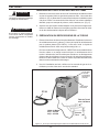
ESAB ESP-150 Plasma Cutting System Manuale utente
- Tipo
- Manuale utente

0558003744 08/2014
This manual provides installation and operation instructions for the following components beginning with Serial
Number PORJ129127:
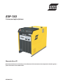
ESP-150
Plasma Cutting System
Instruction Manual

2
DECLARATION OF CONFORMITY
According to
The Low Voltage Directive 2006/95/EC of 12 December 2006, entering into force 16 January 2007
The EMC Directive 2004/108/EC
FÖRSÄKRAN OM ÖVERENSSTÄMMELSE
Lågspänningsdirektivet 2006/95/EG från 12 december 2006, ikraftsat 16 januari 2007
EMC-Direktivet 2004/108/EG
Type of equipment Materialslag
Plasma Cutting Console
Brand name or trade mark Fabrikatnamn eller varumärke
ESAB
Type designation etc. Typbeteckning etc.
ESP-150 Console - 0558002713
Manufacturer or his authorised representative established within the EEA
Name, address, telephone No, telefax No: Tillverkarens namn, adress, telefon, telefax:
ESAB AB
Esabvägen, SE-695 81 Laxå, Sweden
Phone: +46 586 81000, Fax: +46 584 411 924
The following harmonised standard in force within the EEA has been used in the design:
Följande harmoniserande standarder har använts i konstruktionen:
EN 60974-1, Arc welding equipment – Part 1: Welding power sources
EN 60974-10, Arc welding equipment – Part 10: Electromagnetic compatibility (EMC) requirements
Additional information: / Tilläggsinformation: Restrictive use, Class A equipment, intended for use in locations other than
residential
By signing this document, the undersigned declares as manufacturer, or the manufacturer’s authorised
representative established within the EEA, that the equipment in question complies with the safety requirements
stated above.
Genom att underteckna detta dokument försäkrar undertecknad såsom tillverkare, eller tillverkarens representant inom
EES, att angiven materiel uppfyller säkerhetskraven angivna ovan.
Date / Datum
Laxå 2009-02-18
Signature / Underskrift Position / Befattning
Global Director
Equipment and Automation
Kent Eimbrodt
Clarification

3
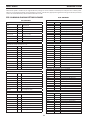
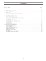
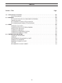
TABLE OF CONTENTS
Instruction Manual (EN) .....................................................................................5
Bedienungsanleitungen (DE)...............................................................................37
Manual de instrucciones (ES) .............................................................................. 69
Manuel d’Instruction (FR) ................................................................................ 101
Manuale d’uso (IT) . . . . . . . . . . . . . . . . . . . . . . . . . . . . . . . . . . . . . . . . . . . . . . . . . . . . . . . . . . . . . . . . . . . . . . . . . . . . . . . . . . . . . . . 133
Manual de Instrução (PT)................................................................................. 163
Section / Title Page

4
TABLE OF CONTENTS

0558003744
ESP-150
Plasma Cutting System
Instruction Manual (EN)

6
This equipment will perform in conformity with the description thereof contained in this manual and accompa-
nying labels and/or inserts when installed, operated, maintained and repaired in accordance with the instruc-
tions provided. This equipment must be checked periodically. Malfunctioning or poorly maintained equipment
should not be used. Parts that are broken, missing, worn, distorted or contaminated should be replaced imme-
diately. Should such repair or replacement become necessary, the manufacturer recommends that a telephone
or written request for service advice be made to the Authorized Distributor from whom it was purchased.
This equipment or any of its parts should not be altered without the prior written approval of the manufacturer.
The user of this equipment shall have the sole responsibility for any malfunction which results from improper
use, faulty maintenance, damage, improper repair or alteration by anyone other than the manufacturer or a ser-
vice facility designated by the manufacturer.
BE SURE THIS INFORMATION REACHES THE OPERATOR.
YOU CAN GET EXTRA COPIES THROUGH YOUR SUPPLIER.
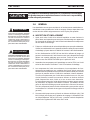
These INSTRUCTIONS are for experienced operators. If you are not fully familiar with the
principles of operation and safe practices for arc welding and cutting equipment, we urge
you to read our booklet, “Precautions and Safe Practices for Arc Welding, Cutting, and
Gouging,” Form 52-529. Do NOT permit untrained persons to install, operate, or maintain
this equipment. Do NOT attempt to install or operate this equipment until you have read
and fully understand these instructions. If you do not fully understand these instructions,
contact your supplier for further information. Be sure to read the Safety Precautions be-
fore installing or operating this equipment.
CAUTION
USER RESPONSIBILITY
READ AND UNDERSTAND THE INSTRUCTION MANUAL BEFORE INSTALLING OR OPERATING.
PROTECT YOURSELF AND OTHERS!

7
TABLE OF CONTENTS
1.0 Safety Precautions .......................................................................... 9
Enclosure Class........................................................................................9
2.0 Description................................................................................ 11
2.1 Specications..................................................................................11
2.2 How to Order ..................................................................................12
2.3 Ordering Information ..........................................................................12
2.4 Optional Accessories ...........................................................................12
2.5 Assembly of PT-26 Front End Parts ..............................................................12
2.6 ESP-150 MANUAL PLASMA CUTTING PACKAGES.................................................14
2.7 ESP-150 Mechanized PLASMA CUTTING PACKAGES..............................................15
3.0 GENERAL.................................................................................. 17
3.1 INSPECTION AND PLACEMENT..................................................................17
3.2 PRIMARY INPUT ELECTRICAL CONNECTIONS ....................................................18
3.3 Voltage Divider Adjustment ................................................................... 22
3.4 TORCH CONNECTIONS . . . . . . . . . . . . . . . . . . . . . . . . . . . . . . . . . . . . . . . . . . . . . . . . . . . . . . . . . . . . . . . . . . . . . . . . 23
3.5 GAS SUPPLY CONNECTIONS ....................................................................24
3.6 WORK and EARTH CONNECTIONS ............................................................. 25
3.7 TORCH COOLANT PREPARATION............................................................... 25
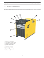
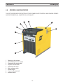
4.0 CONTROLS AND INDICATORS ............................................................... 27
4.1 ESP-150 ADJUSTMENTS ....................................................................... 29
4.2 OPERATION ................................................................................ 29
4.3 STANDOFF AND CUT QUALITY..................................................................31
4.4 DROSS FORMATION............................................................................32
4.5 COMMON CUTTING PROBLEMS ................................................................33
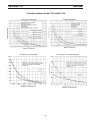
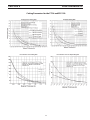
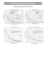
4.6 CUT DATA .................................................................................... 34
4.7 RECOMMENDED GAS AND CURRENT .......................................................... 34
Section / Title Page

8
TABLE OF CONTENTS

9
SECTION 1 SAFETY PRECAUTIONS
1.0 Safety Precautions
Users of ESAB welding and plasma cutting equipment have the ultimate responsibility for ensuring that
anyone who works on or near the equipment observes all the relevant safety precautions. Safety precautions
must meet the requirements that apply to this type of welding or plasma cutting equipment. The following
recommendations should be observed in addition to the standard regulations that apply to the workplace.
All work must be carried out by trained personnel well acquainted with the operation of the welding or plasma
cutting equipment. Incorrect operation of the equipment may lead to hazardous situations which can result in
injury to the operator and damage to the equipment.
1. Anyone who uses welding or plasma cutting equipment must be familiar with:
- its operation
- location of emergency stops
- its function
- relevant safety precautions
- welding and / or plasma cutting
2. The operator must ensure that:
- no unauthorized person stationed within the working area of the equipment when it is started up.
- no one is unprotected when the arc is struck.
3. The workplace must:
- be suitable for the purpose
- be free from drafts
4. Personal safety equipment:
- Always wear recommended personal safety equipment, such as safety glasses, ame proof
clothing, safety gloves.
- Do not wear loose tting items, such as scarves, bracelets, rings, etc., which could become
trapped or cause burns.
5. General precautions:
- Make sure the return cable is connected securely.
- Work on high voltage equipment may only be carried out by a qualied electrician.
- Appropriate re extinquishing equipment must be clearly marked and close at hand.
- Lubrication and maintenance must not be carried out on the equipment during operation.
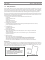
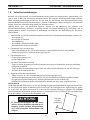
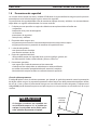
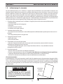
The IP code indicates the enclosure class, i.e. the degree of protection against penetration by solid objects or
water. Protection is provided against touch with a nger, penetration of solid objects greater than 12mm and
against spraying water up to 60 degrees from vertical. Equipment marked IP23S may be stored, but is not in-
tended to be used outside during precipitation unless sheltered.
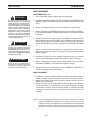
Enclosure Class
Maximum
Tilt Allowed
15°
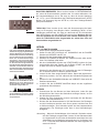
CAUTION
If equipment is placed on a surface that
slopes more than 15°, toppling over may oc-
cur. Personal injury and / or signicant dam-
age to equipment is possible.

10
SECTION 1 SAFETY PRECAUTIONS
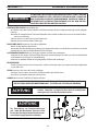
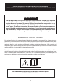
WELDING AND PLASMA CUTTING CAN BE INJURIOUS TO YOURSELF AND
OTHERS. TAKE PRECAUTIONS WHEN WELDING OR CUTTING. ASK FOR
YOUR EMPLOYER’S SAFETY PRACTICES WHICH SHOULD BE BASED ON
MANUFACTURERS’ HAZARD DATA.
ELECTRIC SHOCK - Can kill.
- Install and earth (ground) the welding or plasma cutting unit in accordance with applicable standards.
- Do not touch live electrical parts or electrodes with bare skin, wet gloves or wet clothing.
- Insulate yourself from earth and the workpiece.
- Ensure your working stance is safe.
FUMES AND GASES - Can be dangerous to health.
- Keep your head out of the fumes.
- Use ventilation, extraction at the arc, or both, to take fumes and gases away from your breathing zone
and the general area.
ARC RAYS - Can injure eyes and burn skin.
- Protect your eyes and body. Use the correct welding / plasma cutting screen and lter lens and wear
protective clothing.
- Protect bystanders with suitable screens or curtains.
FIRE HAZARD
- Sparks (spatter) can cause re. Make sure therefore that there are no inammable materials nearby.
NOISE - Excessive noise can damage hearing.
- Protect your ears. Use earmus or other hearing protection.
- Warn bystanders of the risk.
MALFUNCTION - Call for expert assistance in the event of malfunction.
READ AND UNDERSTAND THE INSTRUCTION MANUAL BEFORE INSTALLING OR OPERATING.
PROTECT YOURSELF AND OTHERS!
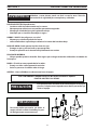
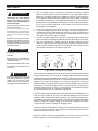
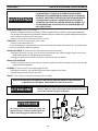
WARNING
This product is solely intended for plasma cutting. Any other
use may result in personal injury and / or equipment damage.
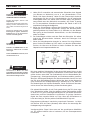
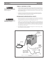
CAUTION
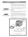
CAUTION
To avoid personal injury and/or equipment
damage, lift using method and attachment
points shown here.

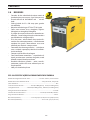
11
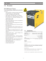
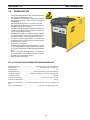
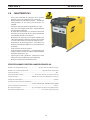
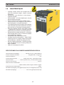
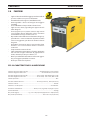
ESP-150 Plasmarc
TM
System
This versatile, all encompassed heavy duty water cooled plasma
cutting and gouging system is ideal for manual and mechanized
applications.
• Greaterproductivity-highspeedcuttingofmostmetals
fromgaugethicknessto2”(50mm)thickplate
• Versatility-380-400/415voltthree-phaseinput
• Greatervariation-adjustableoutput-25to150amps
• Built-InWaterCooler-simpliesmaintenance,lesshook-
up, no wiring issues, no extra hoses. Water ow is con-
trolledwithpowersupply
• WatercooledTorchPT-26
• Leathersheathwrappedtorch-protectstorchleadsfrom
abrasionandmoltenmetal
• Cutswithair,nitrogen,argon-hydrogenmixturesornitro-
gen-hydrogenmixtures
• Built-InCNCinterfaceprovideseasyconnectionofauto-
mationapplications
• Torchdesignprovidesperfectelectrodecentering-pro-
videslongertiplifebyminimizingthepossibilityofdou-
ble-arcing
• Torch spare parts kit supplied with each outt - ample
supplyofsparepartstominimizedowntimeatnoaddi-
tionalcost
• Thermal overload switches - prevents damage if unit
overheatsduetoinsucientairow
• Linevoltagecompensation
• Automaticintermittentcutting - additional capability,
permits continuous cutting of grates, expanded metal,
heavyscreenmaterial,etc.
• Wheelsandcylinderrack-allprovidedstandardforpor-
tabilityandgreaterutilizationatnoadditionalcost
• Idealforplasmagouging
• Threeyearwarrantyonconsole
• OneYearwarrantyontorch
2.1 Specications
Input Current and Input Voltage at Rated Load
.......78A @ 380-400V, 71A @ 415V, 380-400 / 415 Vac, 3 Phase 50/60 Hz
Power Factor .............................................................................................................54%
Output Current Rating .................150 Amps (40% Duty), 110A (100% Duty)
Output Voltage ............................ 140 VDC (40% Duty), 124VDC (100% Duty)
Open circuit Voltage ........................................................................................ 370 vdc
Dimensions ............................................................................ w = 21.75 in. (552mm)
..................................................................................................h = 31.5 in. (800mm)
...................................................................................................d = 40 in. (1016mm)
Weight ..................................................................................................766 lbs. (348 kg)
Plasma Gas (Cutting) .....N2 or Air @ 25psi (25 cfh) or H-35 @ 65psi (75 cfh)
Plasma Gas (Gouging) ..........................................H-35 or Air @ 20 psi (130 cfh)
SECTION 2 DESCRIPTION
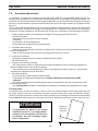
2.0 Description
Duty cycle
The duty cycle refers to the time as a percentage of a ten-minute
period that you can weld at a cer tain load without overloading.
The duty cycle is valid for 40°C.
Enclosure class
The IP code indicates the enclosure class, i. e. the degree of pro-
tection against penetration by solid objects or water.
The power source is supplied with coolant & instruction manual.
Torch
PT-26 - 70°, 90° or In-Line

12
2.2 How to Order
The ESP-150 package includes console, PT-26 torch with leather
sheath, torch spare parts kit, 25 ft. or 50 ft. work cable, TR-21 truck
with dual cylinder rack, regulators and gas hoses and torch coolant.
ESAB can provide you with all necessary welding protection and
accessories.
2.3 Ordering Information
ESP-150 Packages
230/460/575 V, 60Hz, 3 Phase
ESP-150, 25’ PT-26 70° Air .................................................................0558002909
ESP-150, 50’ PT-26 70° Air .................................................................0558002910
ESP-150, 25’ PT-26 90° Air .................................................................0558002911
ESP-150, 50’ PT-26 90° Air .................................................................0558002912
ESP-150, 25’ PT-26 Inline/Air ............................................................ 0558002913
ESP-150, 50’ PT-26 Inline/Air ............................................................ 0558002914
ESP-150, 25’ PT-26 70° Ar+H
2
Mix ...................................................0558002915
ESP-150, 50’ PT-26 70° Ar+H
2
Mix ...................................................0558002916
ESP-150, 25’ PT-26 90° Ar+H
2
Mix ...................................................0558002917
ESP-150, 50’ PT-26 90° Ar+H
2
Mix ...................................................0558002918
ESP-150, 25’ PT-26 Inline/Ar+H
2
Mix .............................................0558002919
ESP-150, 50’ PT-26 Inline/Ar+H
2
Mix .............................................0558002920
ESP-150 Console Only
230/460/575V, 60 Hz, 3 Phase .........................................................0558002677
NOTE: Contact your ESAB Representative to substitute console.
2.4 Optional Accessories
150 amp Spare Parts Kit ..............................................................0558002864
Remote Hand Switch
Permits remote starting and stopping of cutting process;
used primarily for mechanized cutting .........................................2075600
25 ft. Leather Sheath*
Protects torch leads from abrasion and molten metal; particularly ....
recommended for plasma gouging .............................................0558002921
50 ft. Leather Sheath* ...................................................................0558002922
Plasma Flow Measuring Kit
This valuable troubleshooting tool allows measurement of the ..........
actual plasma gas ow through the torch ........................................ 19765
Plasma Torch Head Protector
For gouging ................................................................................................. 20806
Trigger Latch Kit
(FactoryInstalledOnly) ..................................................................0588000939
*Standard on manual torches.
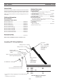
SECTION 2 DESCRIPTION
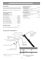
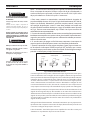
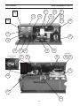
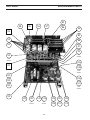
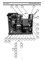
Torch Head -
90° ..................... 34599
70° .......... 0558002204
IN-LINE ..0558002110
Includes O-Rings
2110706 (1)
2029450 (3)
Bae Tube - 34585
O-Ring Location - 2029450
O-Ring Location - 2110706
Electrode
36565 - Air, Nitrogen, Nitrogen/Hydrogen
36566 - Argon/Hydrogen (H-35)
Std. Heat Shield - 34592
*Close Proximity Heat Shield - 37146
Insulator - 34593
Includes O-Ring
- 84W87
Electrode Holder
- 34583
Includes O-Rings
85W49 (Upper)
948317 (Lower)
Stand-O Guide - 36648
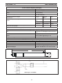
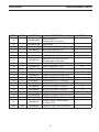
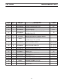
2.5 Assembly of PT-26 Front End Parts
* For use when cutting or gouging in close proximity of
workpiece.
Standard on In-line version.
AMPS P/N ORIFICE SIZE
Cutting Nozzle
150 36568 .078
200 36569 .089
300 36570 .104
Gouging Nozzle
200 36571 .125
300 36572 .144
All include O-Rings 2110578 (Upper)
994092 (Lower)

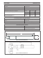
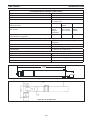
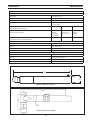
13
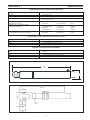
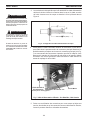
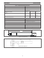
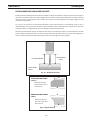
Figure 2 - PT-26 Manual Torch Dimensions
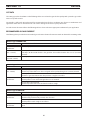
PT-26 Technical Specications (Plasma Gas)
Type of Gas N
2
, Air, AR-H
2
, N
2
-H
2
Pressure 100 psig (6.9 bar)
Flow 240 cfh (6.8 M
3
/h)
Purity Required O
2
- 99.5% min., N
2
-99.995% min., Air - clean and dry
Recommended Liquid Cylinder Service Regulators Inert Gas R-76-150-580LC 19977
Recommended cylinder 2-Stage Regulators Argon-Hydrogen R-77-75-350 998341
Nitrogen R-77-75-580 998343
Industrial Air R-77-150-590 998348
Recommended Heavy-Duty Hi-Flow
Station or Pipeline Regulators
Nitrogen R-76-75-034 19155
PT-26 Technical Specications (Starting Gas/Cutting Gas)
Type N
2
, Air (for Ar-H
2
Cut Gas Use N
2
or Ar-H
2
)
Pressure 100 psig (6.9 bar
Flow 200 cfh (5.66M
3
/h) @ 60 psig (4.1 bar)
Purity Required N
2
- 99% min., Air - clean and dry
PT-26 Technical Specications (Shield Gas)
Type N
2
or Air
Pressure 100 psig (6.9 bar) maximum
Flow 200 cfh (5.66 M
3
/h) @ 85 psig (5.86 bar)
Purity Required Nitrogen - 99% minimum, Air - clean and dry
Figure 1 - PT-26 In-line Torch Dimensions
2”
(50.8)
16.5”
(419mm)
SECTION 2 DESCRIPTION

14
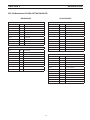
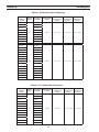
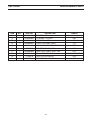
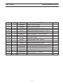
2.6 ESP-150 MANUAL PLASMA CUTTING PACKAGES
AIR PACKAGES
Ar/H
2
PACKAGES
The ESP-150 system is available as pre-engineered basic packages or can be ordered as individual parts and pieces for a custom system.
The basic pre-engineered systems contain the ESP-150 console, plasma torch, appropriate regulators for the gases indicated, and torch
coolant. For torch information, refer to the PT-26 manual F-15-345.
0558002915 - ESP-150 / PT-26 25’ 70° / Ar+H2 Mix
P/N QTY DESCRIPTION
0558002677 1 ESP-150 Console
0558002208 1 PT-26, 70°, 25’ Plasma Torch
0558002864 1 PT-26 Spare Parts Kit, 150A
998341 2 Argon/Hydrogen Mix Regulator
998343 1 Nitrogen Regulator
33122 3 Hoses
678723 1 Work Cable, 25’
19X54 2 Adaptors
156F05 4 Coolant (4 gallons)
680794 1 Truck & CyIinder Rack
0558002910 - ESP-150 / PT-26 50’ 70° / Air
P/N QTY DESCRIPTION
0558002677 1 ESP-150 Console
0558002209 1 PT-26, 70°, 50’ Plasma Torch
0558002864 1 PT-26 Spare Parts Kit, 150A
0558003242 3 Air Reg. Assembly
678724 1 Work Cable, 50’
74S76 3 Adaptors
19416 3 Gas Hose
36933GY 1 Reg. Mount
156F05 4 Coolant (4 gallons)
680794 1 Truck & CyIinder Rack
0558002916 - ESP-150 / PT-26 50’ 70° / Ar+H2 Mix
P/N QTY DESCRIPTION
0558002677 1 ESP-150 Console
0558002209 1 PT-26, 70°, 50’ Plasma Torch
0558002864 1 PT-26 Spare Parts Kit, 150A
998341 2 Argon/Hydrogen Mix Regulator
998343 1 Nitrogen Regulator
33122 3 Hoses
678724 1 Work Cable, 50’
19X54 2 Adaptors
156F05 4 Coolant (4 gallons)
680794 1 Truck & CyIinder Rack
0558002911 - ESP-150 / PT-26 25’ 90° / Air
P/N QTY DESCRIPTION
0558002677 1 ESP-150 Console
36558 1 PT-26, 90°, 25’ Plasma Torch
0558002864 1 PT-26 Spare Parts Kit, 150A
0558003242 3 Air Reg. Assembly
678723 1 Work Cable, 25’
156F05 4 Coolant (4 gallons)
680794 1 Truck & CyIinder Rack
0558002917 - ESP-150 / PT-26 25’ 90° / Ar+H2 Mix
P/N QTY DESCRIPTION
0558002677 1 ESP-150 Console
36558 1 PT-26, 90°, 25’ Plasma Torch
0558002864 1 PT-26 Spare Parts Kit, 150A
998341 2 Argon/Hydrogen Mix Regulator
998343 1 Nitrogen Regulator
33122 3 Hoses
678723 1 Work Cable, 25’
19X54 2 Adaptors
156F05 4 Coolant (4 gallons)
680794 1 Truck & CyIinder Rack
0558002912 - ESP-150 / PT-26 50’ 90° / Air
P/N QTY DESCRIPTION
0558002677 1 ESP-150 Console
36559 1 PT-26, 90°, 50’ Plasma Torch
0558002864 1 PT-26 Spare Parts Kit, 150A
0558003242 3 Air Reg. Assembly
678724 1 Work Cable, 50’
156F05 4 Coolant (4 gallons)
680794 1 Truck & CyIinder Rack
0558002918 - ESP-150 / PT-26 50’ 90° / Ar+H2 Mix
P/N QTY DESCRIPTION
0558002677 1 ESP-150 Console
36559 1 PT-26, 90°, 50’ Plasma Torch
0558002864 1 PT-26 Spare Parts Kit, 150A
998341 2 Argon/Hydrogen Mix Regulator
998343 1 Nitrogen Regulator
33122 3 Hoses
678724 1 Work Cable, 50’
19X54 2 Adaptors
156F05 4 Coolant (4 gallons)
680794 1 Truck & CyIinder Rack
0558002909 - ESP-150 / PT-26 25’ 70° / Air
P/N QTY DESCRIPTION
0558002677 1 ESP-150 Console
0558002208 1 PT-26, 70°, 25’ Plasma Torch
0558002864 1 PT-26 Spare Parts Kit, 150A
0558003242 1 Air Reg. Assembly
678724 1 Work Cable, 50’
156F05 4 Coolant (4 gallons)
680794 1 Truck & CyIinder Rack
SECTION 2 DESCRIPTION

15
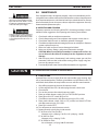
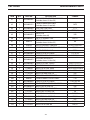
AIR PACKAGES
Ar/H
2
PACKAGES
0558002913 - ESP-150 / PT-26 25’ Inline / Air
P/N QTY DESCRIPTION
0558002677 1 ESP-150 Console
0558002320 1 PT-26, 25’ Inline Plasma Torch
0558002864 1 PT-26 Spare Parts Kit, 150A
0558003242 3 Air Reg. Assembly
678723 1 Work Cable, 25’
33053 1 Strain Relief
951188 1 Locknut
156F05 4 Coolant (4 gallons)
680794 1 Truck & CyIinder Rack
0558002919 - ESP-150 / PT-26 25’ Inline / Ar+H2 Mix
P/N QTY DESCRIPTION
0558002677 1 ESP-150 Console
0558002320 1 PT-26, 25’ Inline Plasma Torch
0558002864 1 PT-26 Spare Parts Kit, 150A
998341 2 Argon/Hydrogen Mix Regulator
998343 1 Nitrogen Regulator
33122 3 Hoses
678723 1 Work Cable, 25’
33053 1 Strain Relief
951188 1 Locknut
19X54 2 Adaptors
156F05 4 Coolant (4 gallons)
680794 1 Truck & CyIinder Rack
0558002914 - ESP-150 / PT-26 50’ Inline / Air
P/N QTY DESCRIPTION
0558002677 1 ESP-150 Console
0558002321 1 PT-26, 50’ Inline Plasma Torch
0558002864 1 PT-26 Spare Parts Kit, 150A
0558003242 3 Air Reg. Assembly
678724 1 Work Cable, 50’
33053 1 Strain Relief
951188 1 Locknut
156F05 4 Coolant (4 gallons)
680794 1 Truck & CyIinder Rack
0558002920 - ESP-150 / PT-26-50’ Inline / Ar+H2 Mix
P/N QTY DESCRIPTION
0558002677 1 ESP-150 Console
0558002321 1 PT-26, 50’ Inline Plasma Torch
0558002864 1 PT-26 Spare Parts Kit, 150A
998341 2 Argon/Hydrogen Mix Regulator
998343 1 Nitrogen Regulator
33122 3 Hoses
678724 1 Work Cable, 50’
33053 1 Strain Relief
951188 1 Locknut
19X54 2 Adaptors
156F05 4 Coolant (4 gallons)
680794 1 Truck & CyIinder Rack
SECTION 2 DESCRIPTION
2.7 ESP-150 Mechanized PLASMA CUTTING PACKAGES

16
SECTION 2 DESCRIPTION

17
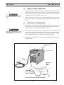
3.0 GENERAL
Proper installation can contribute materially to satisfactory and trouble-free
operation of the cutting outt. Each step in this section should be studied
carefully and followed as closely as possible.
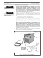
3.1 INSPECTION AND PLACEMENT
1. Having removed the shipping container, and before removing the skid,
inspect for evidence of concealed damage which may not have been
apparent upon receipt of the unit. Notify the carrier of any defects or
damage at once.
2. Check the container for any loose parts. Check air passages on rear panel
of cabinet for any packing materials that may obstruct air ow through
the power supply.
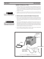
The ESP-150 Power Source is equipped with one lifting eye that enables
hoisting the unit. Be sure the lifting device has adequate capacity to lift
the unit safely. Refer to the SPECIFICATIONS for the unit weight.
3. Mount the components of the TR-21 Truck Kit to the unit as covered by
Form F-14-413 packed with the truck kit.
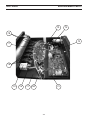
4. The machine components are maintained at proper operating tempera-
tures by forced air which is drawn through the front panel louvers and
holes in the base and out the rear panel by a heavy-duty fan. Locate this
machine in an open area where air can circulate freely through the open-
ings. Leave at least two feet of clearance between the unit and wall or
other obstruction. The area around the unit should be relatively free of
dust, fumes and excessive heat. (Installingorplacinganytypeofltering
devicewillrestrictthevolumeofintakeair,therebysubjectingthepower
sourceinternalcomponentstooverheating.Useofanytypeoflterdevice
voidsthewarranty.)
5. A source of clean, dry air that supplies a minimum of 250cfh (7.08 M
3
H at
110 psig) is required for the cutting operation. The air supply should not
exceed 150psig (10.3 bars) - maximum inlet pressure rating of the lter
regulator supplied with the package.
Precautionary measures should be taken
to provide maximum protection against
electrical shock. Be sure that all power is
o by opening the line (wall) disconnect
switch and unplug the power cord to the
unit when primary electrical connections
are made to the power supply.
ELECTRIC SHOCK CAN KILL! Precaution-
ary measures should be taken to provide
maximum protection against electric
shock. Be sure that all power is off by
opening the line (wall) disconnect switch
and by unplugging the power cord to the
unit when connections are made inside of
the power source.
SECTION 3 INSTALLATION
This product is intended for industrial use. In a domestic environment
this product maycause radio interference. It is the user's responsibility
to take adequate precautions.
CAUTION

18
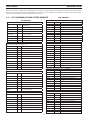
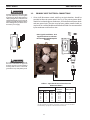
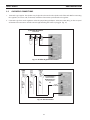
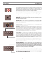
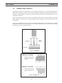
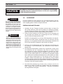
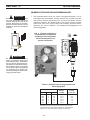
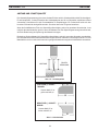
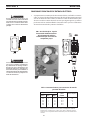
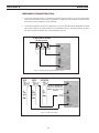
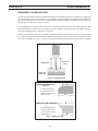
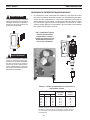
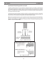
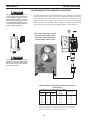
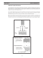
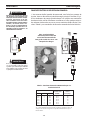
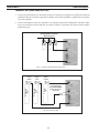
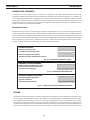
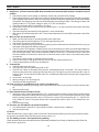
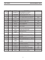
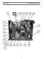
3.2 PRIMARY INPUT ELECTRICAL CONNECTIONS
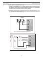
1. A line (wall) disconnect switch, with fuse or circuit breakers, should be
provided at the main power panel. See Fig. 3. The primary power leads
should be insulated copper conductors, and include three power leads
and one ground wire. The wires may be heavy rubber covered cable, or
may be run in a solid or exible conduit. Refer to Table 1 for recommended
input conductors and line fuse sizes.
It is of the utmost importance that the
chassis be connected to an approved
electrical ground to prevent accidental
shocking. Take care not to connect the
ground wire to any of the primary leads.
Precautionary measures should be taken
to provide maximum protection against
electrical shock. Be sure that all power is
o by opening the line (wall) disconnect
switch and unplug the power cord to the
unit use proper lock out safety procedures
when making primary electrical connec-
tions to the power supply.
FIG 3. Typical Installation - User
Supplied 3 Phase Fused Power
Disconnect Box with Recepticle
and Plug
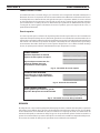
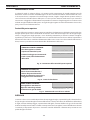
Input Requirements Input & Gnd. Fuse Ratings
Conductor /Phase, Amps
Volts Phase Amps CU/AWG
220 3 121 No. 1 150
230 3 116 No. 1 150
380 3 70 No. 4 100
415 3 64 No. 6 90
460 3 58 No. 6 80
575 3 45 No. 6 70
Table 3-1. Input Conductor and Line Fuse Size
Recommendations
Sizes per National Electrical Code for 75
o
rated conductors @ 30
o
C ambient.
Not more than three conductors in raceway or cable. Local codes should be
followed if they specify sizes other than those listed above.
SECTION 3 INSTALLATION

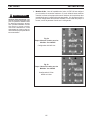
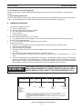
19
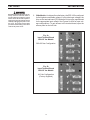
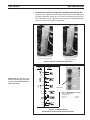
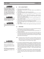
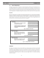
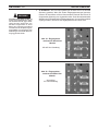
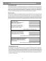
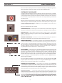
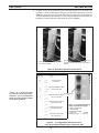
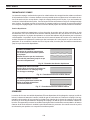
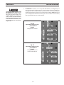
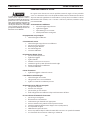
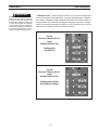
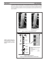
SECTION 3 INSTALLATION
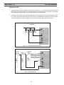
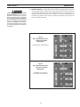
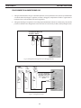
Fig. 5a
Input Terminal Board
380/415 Vac Models
380-400 Vac Conguration
Fig. 5b
Input Terminal Board
380/415 Vac Models
415 Vac Conguration
(Factory Supplied)
ELECTRIC SHOCK CAN KILL! Precau-
tionary measures should be taken to
provide maximum protection against
electric shock. Be sure that all power is
off by opening the line (wall) disconnect
switch by unplugging the power cord to
the unit or use proper lock out safety
procedures when making connections
inside of the power source.
2. 50 Hz Models - As shipped from the factory, the ESP-150 is congured
for the highest connectable voltage. If using other input voltages, the
links on the terminal board (TB) inside the unit must be repositioned
for the appropriate input voltage. See Figures 5a & 5b for input volt-
age congurations. To gain access to the terminal board, open the
access panel on the left side.

20
Before making any connections to the
power source output terminals, make
sure that all primary input power to the
machine is de-energized (o) at the dis-
connect switch.
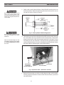
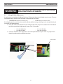
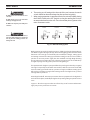
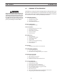
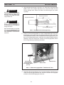
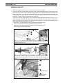
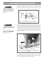
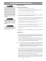
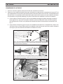
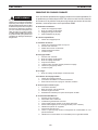
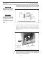
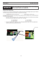
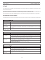
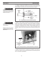
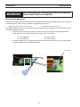
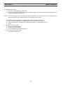
3. Safety codes specify that the Power Cable GROUND wire be the last to
break connection should the cable be pulled out of the unit. Be sure to
cut and strip wire as shown in Figure 6.
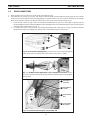
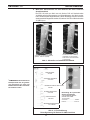
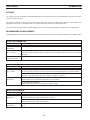
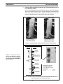
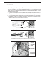
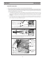
4. Thread the input conductor cable from the wall disconnect switch through
the strain relief in the rear panel of the main contactor (MC). Connect the
primary power leads to the main contactor terminals (see Figure 7) using
UL listed pressure wire connectors. Also connect the ground wire to the
stud provided on the chassis base inside the left-rear of the cabinet. Secure
the input cable by tightening the strain relief coupling.
5. Recheck all connections to make sure that they are tight, well insulated,
and the proper connection has been made. Then close access panel and
reinstall fasteners.
A poor connection or failure to connect
work cable to workpiece can result in
fatal shock.
Failure to connect the workpiece to earth
ground will result in the opening of FUSE
F3 and CIRCUIT BREAKER CB1, disabling
the console.
Fig. 6 - Primary Power Cable Conguration
4-Conductor
InputCable
(Customer Supplied)
Fig. 7 Input Power Cable - Detail View, Left Side
Ground Stud
Green Conductor
SECTION 3 INSTALLATION
La pagina si sta caricando...
La pagina si sta caricando...
La pagina si sta caricando...
La pagina si sta caricando...
La pagina si sta caricando...
La pagina si sta caricando...
La pagina si sta caricando...
La pagina si sta caricando...
La pagina si sta caricando...
La pagina si sta caricando...
La pagina si sta caricando...
La pagina si sta caricando...
La pagina si sta caricando...
La pagina si sta caricando...
La pagina si sta caricando...
La pagina si sta caricando...
La pagina si sta caricando...
La pagina si sta caricando...
La pagina si sta caricando...
La pagina si sta caricando...
La pagina si sta caricando...
La pagina si sta caricando...
La pagina si sta caricando...
La pagina si sta caricando...
La pagina si sta caricando...
La pagina si sta caricando...
La pagina si sta caricando...
La pagina si sta caricando...
La pagina si sta caricando...
La pagina si sta caricando...
La pagina si sta caricando...
La pagina si sta caricando...
La pagina si sta caricando...
La pagina si sta caricando...
La pagina si sta caricando...
La pagina si sta caricando...
La pagina si sta caricando...
La pagina si sta caricando...
La pagina si sta caricando...
La pagina si sta caricando...
La pagina si sta caricando...
La pagina si sta caricando...
La pagina si sta caricando...
La pagina si sta caricando...
La pagina si sta caricando...
La pagina si sta caricando...
La pagina si sta caricando...
La pagina si sta caricando...
La pagina si sta caricando...
La pagina si sta caricando...
La pagina si sta caricando...
La pagina si sta caricando...
La pagina si sta caricando...
La pagina si sta caricando...
La pagina si sta caricando...
La pagina si sta caricando...
La pagina si sta caricando...
La pagina si sta caricando...
La pagina si sta caricando...
La pagina si sta caricando...
La pagina si sta caricando...
La pagina si sta caricando...
La pagina si sta caricando...
La pagina si sta caricando...
La pagina si sta caricando...
La pagina si sta caricando...
La pagina si sta caricando...
La pagina si sta caricando...
La pagina si sta caricando...
La pagina si sta caricando...
La pagina si sta caricando...
La pagina si sta caricando...
La pagina si sta caricando...
La pagina si sta caricando...
La pagina si sta caricando...
La pagina si sta caricando...
La pagina si sta caricando...
La pagina si sta caricando...
La pagina si sta caricando...
La pagina si sta caricando...
La pagina si sta caricando...
La pagina si sta caricando...
La pagina si sta caricando...
La pagina si sta caricando...
La pagina si sta caricando...
La pagina si sta caricando...
La pagina si sta caricando...
La pagina si sta caricando...
La pagina si sta caricando...
La pagina si sta caricando...
La pagina si sta caricando...
La pagina si sta caricando...
La pagina si sta caricando...
La pagina si sta caricando...
La pagina si sta caricando...
La pagina si sta caricando...
La pagina si sta caricando...
La pagina si sta caricando...
La pagina si sta caricando...
La pagina si sta caricando...
La pagina si sta caricando...
La pagina si sta caricando...
La pagina si sta caricando...
La pagina si sta caricando...
La pagina si sta caricando...
La pagina si sta caricando...
La pagina si sta caricando...
La pagina si sta caricando...
La pagina si sta caricando...
La pagina si sta caricando...
La pagina si sta caricando...
La pagina si sta caricando...
La pagina si sta caricando...
La pagina si sta caricando...
La pagina si sta caricando...
La pagina si sta caricando...
La pagina si sta caricando...
La pagina si sta caricando...
La pagina si sta caricando...
La pagina si sta caricando...
La pagina si sta caricando...
La pagina si sta caricando...
La pagina si sta caricando...
La pagina si sta caricando...
La pagina si sta caricando...
La pagina si sta caricando...
La pagina si sta caricando...
La pagina si sta caricando...
La pagina si sta caricando...
La pagina si sta caricando...
La pagina si sta caricando...
La pagina si sta caricando...
La pagina si sta caricando...
La pagina si sta caricando...
La pagina si sta caricando...
La pagina si sta caricando...
La pagina si sta caricando...
La pagina si sta caricando...
La pagina si sta caricando...
La pagina si sta caricando...
La pagina si sta caricando...
La pagina si sta caricando...
La pagina si sta caricando...
La pagina si sta caricando...
La pagina si sta caricando...
La pagina si sta caricando...
La pagina si sta caricando...
La pagina si sta caricando...
La pagina si sta caricando...
La pagina si sta caricando...
La pagina si sta caricando...
La pagina si sta caricando...
La pagina si sta caricando...
La pagina si sta caricando...
La pagina si sta caricando...
La pagina si sta caricando...
La pagina si sta caricando...
La pagina si sta caricando...
La pagina si sta caricando...
La pagina si sta caricando...
La pagina si sta caricando...
La pagina si sta caricando...
La pagina si sta caricando...
La pagina si sta caricando...
La pagina si sta caricando...
La pagina si sta caricando...
La pagina si sta caricando...
La pagina si sta caricando...
La pagina si sta caricando...
La pagina si sta caricando...
La pagina si sta caricando...
La pagina si sta caricando...
La pagina si sta caricando...
La pagina si sta caricando...
La pagina si sta caricando...
La pagina si sta caricando...
La pagina si sta caricando...
La pagina si sta caricando...
La pagina si sta caricando...
La pagina si sta caricando...
La pagina si sta caricando...
La pagina si sta caricando...
La pagina si sta caricando...
La pagina si sta caricando...
La pagina si sta caricando...
La pagina si sta caricando...
La pagina si sta caricando...
La pagina si sta caricando...
La pagina si sta caricando...
La pagina si sta caricando...
La pagina si sta caricando...
La pagina si sta caricando...
La pagina si sta caricando...
La pagina si sta caricando...
La pagina si sta caricando...
La pagina si sta caricando...
La pagina si sta caricando...
La pagina si sta caricando...
La pagina si sta caricando...
La pagina si sta caricando...
La pagina si sta caricando...
La pagina si sta caricando...
-
 1
1
-
 2
2
-
 3
3
-
 4
4
-
 5
5
-
 6
6
-
 7
7
-
 8
8
-
 9
9
-
 10
10
-
 11
11
-
 12
12
-
 13
13
-
 14
14
-
 15
15
-
 16
16
-
 17
17
-
 18
18
-
 19
19
-
 20
20
-
 21
21
-
 22
22
-
 23
23
-
 24
24
-
 25
25
-
 26
26
-
 27
27
-
 28
28
-
 29
29
-
 30
30
-
 31
31
-
 32
32
-
 33
33
-
 34
34
-
 35
35
-
 36
36
-
 37
37
-
 38
38
-
 39
39
-
 40
40
-
 41
41
-
 42
42
-
 43
43
-
 44
44
-
 45
45
-
 46
46
-
 47
47
-
 48
48
-
 49
49
-
 50
50
-
 51
51
-
 52
52
-
 53
53
-
 54
54
-
 55
55
-
 56
56
-
 57
57
-
 58
58
-
 59
59
-
 60
60
-
 61
61
-
 62
62
-
 63
63
-
 64
64
-
 65
65
-
 66
66
-
 67
67
-
 68
68
-
 69
69
-
 70
70
-
 71
71
-
 72
72
-
 73
73
-
 74
74
-
 75
75
-
 76
76
-
 77
77
-
 78
78
-
 79
79
-
 80
80
-
 81
81
-
 82
82
-
 83
83
-
 84
84
-
 85
85
-
 86
86
-
 87
87
-
 88
88
-
 89
89
-
 90
90
-
 91
91
-
 92
92
-
 93
93
-
 94
94
-
 95
95
-
 96
96
-
 97
97
-
 98
98
-
 99
99
-
 100
100
-
 101
101
-
 102
102
-
 103
103
-
 104
104
-
 105
105
-
 106
106
-
 107
107
-
 108
108
-
 109
109
-
 110
110
-
 111
111
-
 112
112
-
 113
113
-
 114
114
-
 115
115
-
 116
116
-
 117
117
-
 118
118
-
 119
119
-
 120
120
-
 121
121
-
 122
122
-
 123
123
-
 124
124
-
 125
125
-
 126
126
-
 127
127
-
 128
128
-
 129
129
-
 130
130
-
 131
131
-
 132
132
-
 133
133
-
 134
134
-
 135
135
-
 136
136
-
 137
137
-
 138
138
-
 139
139
-
 140
140
-
 141
141
-
 142
142
-
 143
143
-
 144
144
-
 145
145
-
 146
146
-
 147
147
-
 148
148
-
 149
149
-
 150
150
-
 151
151
-
 152
152
-
 153
153
-
 154
154
-
 155
155
-
 156
156
-
 157
157
-
 158
158
-
 159
159
-
 160
160
-
 161
161
-
 162
162
-
 163
163
-
 164
164
-
 165
165
-
 166
166
-
 167
167
-
 168
168
-
 169
169
-
 170
170
-
 171
171
-
 172
172
-
 173
173
-
 174
174
-
 175
175
-
 176
176
-
 177
177
-
 178
178
-
 179
179
-
 180
180
-
 181
181
-
 182
182
-
 183
183
-
 184
184
-
 185
185
-
 186
186
-
 187
187
-
 188
188
-
 189
189
-
 190
190
-
 191
191
-
 192
192
-
 193
193
-
 194
194
-
 195
195
-
 196
196
-
 197
197
-
 198
198
-
 199
199
-
 200
200
-
 201
201
-
 202
202
-
 203
203
-
 204
204
-
 205
205
-
 206
206
-
 207
207
-
 208
208
-
 209
209
-
 210
210
-
 211
211
-
 212
212
-
 213
213
-
 214
214
-
 215
215
-
 216
216
-
 217
217
-
 218
218
-
 219
219
-
 220
220
-
 221
221
-
 222
222


ESAB ESP-150 Plasma Cutting System Manuale utente
- Tipo
- Manuale utente
in altre lingue
- English: ESAB ESP-150 Plasma Cutting System User manual
- français: ESAB ESP-150 Plasma Cutting System Manuel utilisateur
- español: ESAB ESP-150 Plasma Cutting System Manual de usuario
- Deutsch: ESAB ESP-150 Plasma Cutting System Benutzerhandbuch
- português: ESAB ESP-150 Plasma Cutting System Manual do usuário
Documenti correlati
-
ESAB ESP-150 Manuale utente
-
ESAB Speedloader/XR Speedloader Manuale utente
-
-
-
ESAB EPP-200 Precision Plasmarc Cutting System Manuale utente
-
-
-
-
-
Altri documenti
-
GYS PLASMA CUTTER NEOCUT 105 Manuale del proprietario
-
Rothenberger Soldering torch QUICK FIRE Manuale utente
-
GCE GCEproFIT® SLM Istruzioni per l'uso
-
Ingersoll-Rand Sierra SL 90 Operation and Maintenance Manual
-
Cebora Plasma PROF 166 HQC Manuale utente
-
-