
Manual for
BAL.NR.00 03 90 15
0,;,1*3803
3)7*F
WE KEEP THINGS MOVING


3)7*F
,QWURGXFWLRQ 9HUVLRQ
BBBBBBBBBBBBBBBBBBBBBBBBBBBBBBBBBBBBBBBBBBBBBBBBBBBBBBBBBBBBBBBBBBBBBBBBBBBBBBBBBBBBBBBB
________________________________________________________________________________________
'HDU&XVWRPHU
Congratulations! You have just made a quality purchase.
The PFT G 5 c is a state-of-the-art machine designed to withstand the tough conditions of construction sites.
Always keep this manual with the machine. The manual provides you with vital information about the
machine’s functions. Read the manual thoroughly before you operate the machine. PFT will not be liable for
accidents and malfunctions that are caused by incorrect operation. Proper operation and maintenance will
make the PFT G 5 c a dependable construction aid.
The PFT G 5 c abides by the stringent safety standards of the German Builder’s Guild and has been granted
the Guild’s certification of approval.
This manual is copyright. No part of this manual or its technical specifications and drawings may be
reproduced, stored in a retrieval system, or transmitted in any form or by any means, electronic, mechanical,
photocopying or otherwise, without the express written consent of PFT Putz- und Fördertechnik GmbH & Co.
KG. Unauthorized reproduction will lead to legal action. All rights reserved.
© PFT Putz- und Fördertechnik GmbH & Co. KG

3)7*F
3)76DOHV,QVWUXFWLRQV 9HUVLRQ
BBBBBBBBBBBBBBBBBBBBBBBBBBBBBBBBBBBBBBBBBBBBBBBBBBBBBBBBBBBBBBBBBBBBBBBBBBBBBBBBBBBBBBBB
________________________________________________________________________________________
)LUVWLQVSHFWLRQDIWHUGHOLYHU\
It is mandatory that all delivery technicians check the machine settings at the end of the first spraying
operation. Factory settings can change during the initial phase of operation. If necessary, resetting should
take place right after initial run, without which faults are likely to set in.
After handing over the machine and approx. two hours after the initial operation, delivery technicians must
inspect the following items and settings:
1. Water safety switch
2. Pump pressure, back pressure
3. Pressure relief valve on compressor
4. Air nozzle tube (Spraying pattern)
5. Air safety switch
6. Compressor pressure switch
7. Remote control switch
8. Pressure reducing valve
9. Motor safety switch
127(
:$55$17<&$5'0867%(),//('$1'5(7851('723)7
12:$55$17<:,7+287:$55$17<&$5'

3)7*F
&RQWHFWV 9HUVLRQ
BBBBBBBBBBBBBBBBBBBBBBBBBBBBBBBBBBBBBBBBBBBBBBBBBBBBBBBBBBBBBBBBBBBBBBBBBBBBBBBBBBBBBBBB
________________________________________________________________________________________
Introduction ....................................................................................................................................................... .1
Contents............................................................................................................................................................. 3
Overview ........................................................................................................................................................... 4
Water Armature.................................................................................................................................................. 5
Operating and Display Elements........................................................................................................................ 6
Air Armature....................................................................................................................................................... 7
Caddy Icons ....................................................................................................................................................... 8
Description of Functions..................................................................................................................................... 9
Basic Safety Instructions................................................................................................................................ . 10
Settings ............................................................................................................................................................ 12
Mortar Pump .................................................................................................................................................... 13
Setting Up the Machine.................................................................................................................................... 16
Mortar Consistency/Spraying Gun and Nozzles (Caps)................................................................................... 21
Interrupting Operation ...................................................................................................................................... 21
Ending Operation and Cleaning Procedure ..................................................................................................... 22
Check List ...................................................................................................................................................... . 24
Procedures for Power Failure/Water Supply Failure........................................................................................ 26
Procedures for Hose Blocks ............................................................................................................................ 26
Procedures for Subzero Temperatures............................................................................................................ 27
Transport.......................................................................................................................................................... 28
Maintenance..................................................................................................................................................... 29
Accessories...................................................................................................................................................... 30
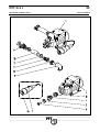
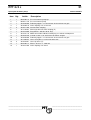
Spare Part List ................................................................................................................................................. 31
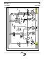
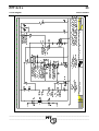
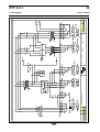
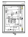
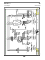
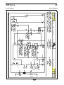
Circuit Diagram ................................................................................................................................................ 32
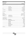
Technical Data ................................................................................................................................................. 52

3)7*F
2YHUYLHZ 9HUVLRQ
BBBBBBBBBBBBBBBBBBBBBBBBBBBBBBBBBBBBBBBBBBBBBBBBBBBBBBBBBBBBBBBBBBBBBBBBBBBBBBBBBBBBBBBB
________________________________________________________________________________________
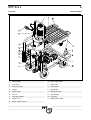
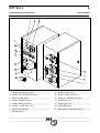
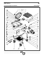
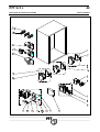
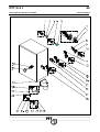
1. Mixing motor 10.
Water connection
2. Star wheel 11.
Water inlet
3. Protection grille 12.
Control box
4. Hopper 13.
Mixing tube
5. Water pump 14.
Mixing tube lock
6. Chassis 15.
Tilted flange
7. Star wheel motor 16.
Fast lock
8. Compressor 17.
Motor power cable
9. Rotor / Stator Twister

3)7*F
:DWHU$UPDWXUH 9HUVLRQ
BBBBBBBBBBBBBBBBBBBBBBBBBBBBBBBBBBBBBBBBBBBBBBBBBBBBBBBBBBBBBBBBBBBBBBBBBBBBBBBBBBBBBBBB
________________________________________________________________________________________
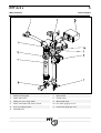
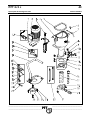
1. Water to mixing tube 7. Water outlet
2. Water outlet valve 8. Needle valve
3. Water pressure safety switch 9. Water flow meter
4. Water connection from mains or tank 10.
Pre-water gauge pressure
5. Pressure reducing valve 11.
Post-water gauge pressure
6. Solenoid valve

3)7*F
2SHUDWLQJDQG'LVSOD\(OHPHQWV 9HUVLRQ
BBBBBBBBBBBBBBBBBBBBBBBBBBBBBBBBBBBBBBBBBBBBBBBBBBBBBBBBBBBBBBBBBBBBBBBBBBBBBBBBBBBBBBBB
________________________________________________________________________________________
1. Display lamp : fault in system 9. Sockets for main 32 A
2. Display lamp : direction of rotation 10.
Remote control socket 42 V
3. Main reversing switch 11.
Hand – 0 – automatic star wheel
4. Socket : compressor 16 A 12.
Display lamp : on
5. Socket : water pump 16 A 13.
Display lamp : off
6. Schuko – socket 230 V, 16 A 14.
Water flow button
7. Socket : mixing pump 15.
Blue switch : pump motor reverse
8. Blind plug 4-pin

3)7*F
$LU$UPDWXUH 9HUVLRQ
BBBBBBBBBBBBBBBBBBBBBBBBBBBBBBBBBBBBBBBBBBBBBBBBBBBBBBBBBBBBBBBBBBBBBBBBBBBBBBBBBBBBBBBB
________________________________________________________________________________________
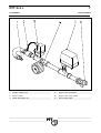
1. Air from compressor 4. Air pressure manometer
2. Reverse valve 10. Air pressure safety switch
3. Switch off compressor 11. Air to spraying gun

3)7*F
,FRQV 9HUVLRQ
BBBBBBBBBBBBBBBBBBBBBBBBBBBBBBBBBBBBBBBBBBBBBBBBBBBBBBBBBBBBBBBBBBBBBBBBBBBBBBBBBBBBBBBB
________________________________________________________________________________________
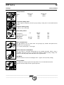
'ULYHV
Star wheel
Water pump
Compressor
Vibrator
,QVWUXFWLRQV
Manual operation
Automatic operation
Water
Air
)DXOWV
Motor safety switch off
No material
No water pressure
Wrong direction
At subzero temperatures empty
All water
Do not insert hand into operating
machine
Maximum operating pressure 40
bar

3)7*F
'HVFULSWLRQRI)XQFWLRQV 9HUVLRQ
BBBBBBBBBBBBBBBBBBBBBBBBBBBBBBBBBBBBBBBBBBBBBBBBBBBBBBBBBBBBBBBBBBBBBBBBBBBBBBBBBBBBBBBB
________________________________________________________________________________________
The PFT G 5 c is a continuous mixing pump for factory-blended dry mortar. It can be
filled either by means of bags, a delivery hood or an injection hood.
)2//2:$//0$7(5,$/0,;,1*,16758&7,216)5200257$5
0$18)$&785(5
The G 5 c consists of individual portable components (modules) whose handy
dimensions and low weight allow for quick and easy transportation.
127(7+()2//2:,1*&211(&7,216:+,/(23(5$7,1*
1. Electrical Panel – Control box
2. Control box - Pump Motor
3. Control box – Star Wheel
4. Control box - Compressor
5. Compressor – Air-Water Manifold
6. Water Mains – Air-Water Manifold
7. Air- Water Manifold – Air Hose
8. Air Hose – Spraying Gun
9. Mixing Tube – Mortar Pressure Gauge
10. Mortar Pressure Gauge – Mortar Hose
11. Mortar Hose – Spraying Gun

3)7*F
%DVLF6DIHW\,QVWUXFWLRQV
9HUVLRQ
BBBBBBBBBBBBBBBBBBBBBBBBBBBBBBBBBBBBBBBBBBBBBBBBBBBBBBBBBBBBBBBBBBBBBBBBBBBBBBBBBBBBBBBB
________________________________________________________________________________________
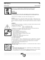
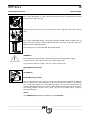
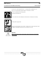
The following terms and symbols are used in this manual to highlight important
information:
127(
Information for running the machine efficiently.
:$51,1*
Precautionary information for the prevention of accidents.
:$51,1*
The machine should only be operated in perfect working conditions. Comply with all
safety instructions in this manual! Rectify all defects and faults immediately. Proper
machine operation includes full compliance with all operating instructions, carrying
out specified inspections, and complying with maintenance instructions. Turn to
page 3 12 05 402, Pt. 20 for more information.
The most important safety instructions follow. 3OHDVH UHDG WKHP WKRURXJKO\.
Comply with these instructions in order to get reliable quality service from the
machine.

3)7*F
%DVLF6DIHW\,QVWUXFWLRQV 9HUVLRQ
BBBBBBBBBBBBBBBBBBBBBBBBBBBBBBBBBBBBBBBBBBBBBBBBBBBBBBBBBBBBBBBBBBBBBBBBBBBBBBBBBBBBBBBB
________________________________________________________________________________________
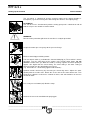
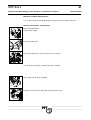
1. Follow all safety instructions on the machine. Ensure that all instructions are legible.
2. Inspect the machine once every shift for visible damages and defects. Stop operating the
machine immediately if you notice any changes in safety or operating behavior. Notify the
construction site supervisor immediately.
3. Do not make any changes to the machine that can jeopardize its safety. Always consult
the machine dealer first. 'R QRW WDPSHU ZLWK WKH PDFKLQH by equipping it with extra
“safety devices“.
4. All spare parts should conform to our technical specifications. Only use spare parts
manufactured by PFT.
5. Only trained personnel should operate the machine. Clearly designate all lines of
responsibility for operation, equipping, maintenance and repairs.
6. Technicians undergoing training in the operation of the machine should be supervised by
experienced personnel.
7. Only qualified personnel should work on the machine’s electrical system. All electrical
work should only take place under the supervision of a qualified electrician and should
comply with electro-technical safety regulations.
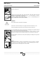
8. Observe all instructions for switching the machine on and off. Watch display lamps for
signals.
9. When the machine is completely switched off for maintenance and repair work, ensure
that it cannot switch back on accidently. Do this by switching off the main switch, removing
the key or by attaching a warning sign to the main switch.
10. Before cleaning the machine with a water jet, seal all openings as water should not enter
electrical parts or caddy. Cover electric motors and control boxes thoroughly. After
cleaning remove all seals and covers.
11. Use only original fuses with prescribed amps.
12. If work has to be carried out on a voltage-conducting component, a second technician
should stand by to switch off mains in case of an emergency.
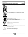
13. Disconnect the machine from the mains before you move it, even if you are only moving it
a short distance. Reconnect the machine to the mains properly before starting up again.
14. Set up the machine on stable ground. Secure it from rolling away or moving during
operation.
15. Lay out all conveying hoses safely. Do not rest them on sharp edges.
16. Depressurize all conveying systems before dismantling conveying hoses.
17. While unclogging hoses stand away from the machine to avoid injury through high
pressure discharges of mortar. Always wear safety goggles. No other person should be
close to the machine when unclogging measures are under way.
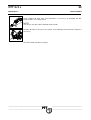
18. Use appropriate noise reduction measures if you exceed a noise level of 85 dB(A) while
operating the machine.
19. Use the following accessories while spraying, if necessary,: safety goggles, construction
site boots, safety clothing, gloves, inhalation mask, skin safety cream.
20. Have the machine inspected at least once a year by a qualified person. The machine
should also be inspected otherwise as required.

3)7*F
6HWWLQJV 9HUVLRQ
BBBBBBBBBBBBBBBBBBBBBBBBBBBBBBBBBBBBBBBBBBBBBBBBBBBBBBBBBBBBBBBBBBBBBBBBBBBBBBBBBBBBBBBB
________________________________________________________________________________________
6DIHW\6ZLWFKHV
Machine on Mashine off
Water 2,2 bar 1,9 bar
Air 2,0 bar 3,0 bar
&RPSUHVVRU6DIHW\9DOYH
5,0 bar against completely closed air pipe (factory setting and secured with knurled
screw)
3UHVVXUHUHGXFLQJYDOYH
1,9 bar at max. water flow
0RWRUVDIHW\VZLWFK
kw Voltage term
Transformer 0,8 A Q2
Vibrator/ Compressor 16 A Q3
Water pump 1,9 A Q4
Star wheel 0,55 kW 1,8 A Q6
Pump motor 5,5 kW 12 A Q7
*DS$LU1R]]OH3LSH
The gap between the air nozzle tube and spraying cap should correspond to the
diameter of the spraying cap.
e.g.: 14 mm spraying cap = 14 mm gap
5RWDWLRQGLUHFWLRQRI6WDU:KHHO
The star wheel is generally independent of the rotation direction. While using a
SILOMAT conveying system, we recommend clockwise rotation (factory setting). This
will ensure that the pump motor will rotate in the right direction.
6WDU:KHHO
Distance between star wheel and hopper base: approx. 8 mm (factory setting)
5XOHRI7KXPE
1,5 x diameter of largest grain of the dry mortar. Fit a star wheel distance disk
(Item No. 20 10 19 00) for coarse-grained plasters.
.

3)7*F
0RUWDU3XPS 9HUVLRQ
BBBBBBBBBBBBBBBBBBBBBBBBBBBBBBBBBBBBBBBBBBBBBBBBBBBBBBBBBBBBBBBBBBBBBBBBBBBBBBBBBBBBBBBB
________________________________________________________________________________________
The PFT G 5 c is equipped with the TWISTER D5-2,5 pumping system.
5RWRUXQG6WDWRUDUHZHDUDQGWHDUSDUWV,QVSHFWWKHPUHJXODUO\
3UHVVXUH
5XOHRIWKXPE
1,0 bar dynamic pressure per meter (conveying hose 25 mm): for gypsum plasters
0,2 - 0,3 bar dynamic pressure per meter (conveying hose 35 mm): for floor screed
The back pressure should be at least 40% of the conveying pressure.
Example:
25 bar conveying pressure (with water) should result in approx. 12 bar back pressure
when the machine is switched off. In the case of gypsum plasters 18-26 bar conveying
pressure should result in approx. 7-8 bar back pressure when the machine is switched
off.
:$51,1*
Use of a mortar pressure gauge is mandatory in accordance with accident prevention
regulations of the Builder’s Guild.
PFT Mortar Pressure Gauge 25 mm Item No. 20 21 70 01
35 mm Item No. 20 21 72 00
PFT Mortar Pressure Gauges monitor the mortar consistency efficiently and easily.
The mortar pressure gauge is delivered with the machine.
Some of its advantages:
- Precise regulation of mortar consistency.
- Constant monitoring of conveying pressure.
- Early detection of clogging or overload of pump motor.
- Produces zero pressure.
- Contributes to the safety of operating personnel.
- Durability of pump components.
3)73XPS&RPSRQHQWV
New pump components with a conveying hose of 10 m should attain a conveying
pressure of approx. 15 - 25 bar respectively and maintain a back pressure of approx.
8 - 12 bar before and after the first spraying. Use the PFT Pressure Tester with
coupling and outlet tap to monitor back pressure.
(Item No. 20 21 68 10)
While fitting and removing pump components, see to it that the main switch is switched
off during assembly.
127(
- a new stator or rotor require a run-in time. Reliable pressure readings can only be
made after one spraying operation.
- Pump components that neither attain the required conveying pressure nor maintain
the required back pressure are worn out. 5(3/$&( them immediately.

3)7*F
0RUWDU3XPS 9HUVLRQ
BBBBBBBBBBBBBBBBBBBBBBBBBBBBBBBBBBBBBBBBBBBBBBBBBBBBBBBBBBBBBBBBBBBBBBBBBBBBBBBBBBBBBBBB
________________________________________________________________________________________
While using adjustable pumps, see to it that :
- the main switch is switched off during assembly.
- the stator protrudes evenly at the ends.
- the pin [1] is between the clamping jaws so that the stator cannot move.
- all screws on the clamp are tightened evenly.
- the tie rods are not too tight, and the stator ends in the flanges are firm and
centrally placed.
- a new stator and rotor require a run-in time. Reliable pressure readings can only be
made after one spraying operation.
- Pump components that neither attain the necessary conveying pressure nor
maintain the necessary back pressure are worn out. 5HSODFH them immediately.
&KHFNLQJWKHFRQYH\LQJSUHVVXUHDQGEDFNSUHVVXUH
- Connect a 10 m conveying hose.
- Couple the pressure tester with outlet tap to the end of hose.
- Open valve.
- Switch on machine and let water run through it until water emerges from the outlet
tap (deaerate hose).
- Shut valve.
- Run the pump under pressure until pressure no longer increases.
- Switch off machine.
- If you do not have the required pressure, replace maintenance-free pump.
- The adjustable pump can either be tightened with a clamp or replaced.
- Check back pressure.
Maintain a back pressure of approx 14 bar through the rotor/stator pump
(D5-2,5 TWISTER) in the hose.
127(
The testing pressure with water should be approx. 5-10 bar above the anticipated
mortar pumping pressure!
Example:
20 m conveying hose (25 mm ∅) with gypsum mortar requires the pump to be
operated at approx. 20 - 25 bar.
If the rotor is placed improperly in the stator, a gurgling sound will occur and water will
flow back into the mixing chamber. Find the proper position in which the rotor seals
with the stator by repeatedly switching the machine on and off.

3)7*F
0RUWDU3XPS 9HUVLRQ
BBBBBBBBBBBBBBBBBBBBBBBBBBBBBBBBBBBBBBBBBBBBBBBBBBBBBBBBBBBBBBBBBBBBBBBBBBBBBBBBBBBBBBBB
________________________________________________________________________________________
127(
1. Stator TWISTER D5-2,5 can be used up to 25 bar operating pressure.
2. The maximum pumping distance depends on the viscosity of the mortar. Coarse-
grained heavy mortar does not flow easily whereas fluid mortars, filling
compounds and floor screed flow easily.
3. Use thick mortar hoses if you exceed an operating pressure of 25 bar.
4. To avoid machine breakdowns and excessive wear and tear of the pump motor,
mixing shaft and pump always use 25,*,1$/3)7 SDUWV such as :
3)75RWRUV
3)76WDWRUV
3)70RUWDU3UHVVXUH+RVHV
3)7&ODPSV
3)70L[LQJVKDIWV
All these components are compatible with each other and form a single construction
unit. If you do not adhere to these recommendations, you stand to forfeit your warranty
rights. The quality of the mortar you are producing will also suffer.

3)7*F
6HWWLQJXSWKHPDFKLQH 9HUVLRQ
BBBBBBBBBBBBBBBBBBBBBBBBBBBBBBBBBBBBBBBBBBBBBBBBBBBBBBBBBBBBBBBBBBBBBBBBBBBBBBBBBBBBBBBB
________________________________________________________________________________________
- Transport all machine modules as close as possible to construction site.
(for assembly see 7UDQVSRUWpage 3 12 01 419)
- Lock the rollers before starting the machine.
- Connect the water system with a ¾“ hose. Open water supply to deaerate and
clean hose. Close water supply.
- Connect water hose to water pump.
Shut deaeration valves on water manifold.
- The fitted water (booster) pump can be used if water pressure falls below 2,5 bar.
+DQG
- Water pump runs continuously (cleaning of hose).
- Water pump is switched off.
$XWRPDWLF
- Water pump runs simultaneously with mixing pump (if you are using stored water
from a tank).
:$51,1*
While working with water from a tank fit the suction inlet with a water filter
(Item No.00 00 69 06 ) (deaeration).
The machine should only be connected to an electrical panel with 32 A and a FI safety
switch that conforms to regulations. The connection cable should conform to the
version H07 RN-F 5x4,0 mm². For 5-pin connection use the Schuko socket for all 230V
gadgets (e.g portable lamps).
We recommend the use of PFT power cable 5x4,0 mm², 50m with CEE plug and
coupling (Item No. 20 42 39 00).
Before the caddy has power supply, see to it that :
- Main reversing switch is switched off (Position “0“, lockable).
- Water pump switch, star wheel switch and compressor switch are switched to “0“.
- Deactivate blind plug.
Connect pump motor (7-pin plug)

3)7*F
6HWWLQJXSWKHPDFKLQH 9HUVLRQ
BBBBBBBBBBBBBBBBBBBBBBBBBBBBBBBBBBBBBBBBBBBBBBBBBBBBBBBBBBBBBBBBBBBBBBBBBBBBBBBBBBBBBBBB
________________________________________________________________________________________
Connect power plug
)ROORZWKHVHLQVWUXFWLRQV
Main reversing switch should be on position I
If red lamp lights up (change direction of rotation), PFT G 5 c will not turn on. Change
direction of rotation at main reversing switch.
,IWKHGLUHFWLRQRIURWDWLRQLVZURQJIROORZWKHVHLQVWUXFWLRQV
You can lock the main reversing switch by pushing the direction plate either to the right
or to the left. With that you have chosen the direction of rotation. If the switch is turned
to the left , it can be turned back to O, but not to the right side. The figure printed on
the plate shows you in what position the switch is locked.
Never let the pump run dry (remove blind plug).
:DUQLQJ
Do not remove protection grill either while preparing to set up machine or during
operation.
If red lamp („change of direction“) does not turn off, see )DXOWVDQG6ROXWLRQV
Press green pressure button (on).

3)7*F
6HWWLQJXSWKHPDFKLQH 9HUVLRQ
BBBBBBBBBBBBBBBBBBBBBBBBBBBBBBBBBBBBBBBBBBBBBBBBBBBBBBBBBBBBBBBBBBBBBBBBBBBBBBBBBBBBBBBB
________________________________________________________________________________________
Press water flow button (1) (water pump should be running). Set approximate amount
of water with needle valve (2).
Connect the water hose of the water flow meter to the top water inlet of the mixing
tube.
Press water flow button briefly. The mixing chamber should contain enough water so
that the top of the rotor is covered. Watch out for loss of water. If you lose water, the
rotor may not be working properly.
Check water level (can be done with tilted pump motor).
:$51,1*
By removing the 7-pin plug of the mixing pump you can interrupt power supply
(safety measure). To restart machine press green button (on).
Set star wheel switch on “Hand“. You can set the star wheel on:
+$1'0DQXDO2SHUDWLRQ
$8720$7,&
+$1'0DQXDO2SHUDWLRQ
The star wheel always runs when the machine is connected and switched on. Material
can be added to the mixing chamber in this position when the pump is not running.
This is called pre-wetting. It is advisable to pre-wet in the case of heavy materials or
materials bonded with dispersion agents. While doing so open the lower water inlet in
the mixing chamber so that excess water can run off. Interrupt power supply by
removing blind plug.
127(
The 7:,67(5' pump should always be SUHZHWWHG!
La pagina si sta caricando...
La pagina si sta caricando...
La pagina si sta caricando...
La pagina si sta caricando...
La pagina si sta caricando...
La pagina si sta caricando...
La pagina si sta caricando...
La pagina si sta caricando...
La pagina si sta caricando...
La pagina si sta caricando...
La pagina si sta caricando...
La pagina si sta caricando...
La pagina si sta caricando...
La pagina si sta caricando...
La pagina si sta caricando...
La pagina si sta caricando...
La pagina si sta caricando...
La pagina si sta caricando...
La pagina si sta caricando...
La pagina si sta caricando...
La pagina si sta caricando...
La pagina si sta caricando...
La pagina si sta caricando...
La pagina si sta caricando...
La pagina si sta caricando...
La pagina si sta caricando...
La pagina si sta caricando...
La pagina si sta caricando...
La pagina si sta caricando...
La pagina si sta caricando...
La pagina si sta caricando...
La pagina si sta caricando...
La pagina si sta caricando...
La pagina si sta caricando...
La pagina si sta caricando...
La pagina si sta caricando...
-
 1
1
-
 2
2
-
 3
3
-
 4
4
-
 5
5
-
 6
6
-
 7
7
-
 8
8
-
 9
9
-
 10
10
-
 11
11
-
 12
12
-
 13
13
-
 14
14
-
 15
15
-
 16
16
-
 17
17
-
 18
18
-
 19
19
-
 20
20
-
 21
21
-
 22
22
-
 23
23
-
 24
24
-
 25
25
-
 26
26
-
 27
27
-
 28
28
-
 29
29
-
 30
30
-
 31
31
-
 32
32
-
 33
33
-
 34
34
-
 35
35
-
 36
36
-
 37
37
-
 38
38
-
 39
39
-
 40
40
-
 41
41
-
 42
42
-
 43
43
-
 44
44
-
 45
45
-
 46
46
-
 47
47
-
 48
48
-
 49
49
-
 50
50
-
 51
51
-
 52
52
-
 53
53
-
 54
54
-
 55
55
-
 56
56


in altre lingue
- English: PFT G 5 c User manual
- français: PFT G 5 c Manuel utilisateur
Documenti correlati

Altri documenti
-
Alto CS 1020 DE Operating Instructions Manual
-
Agria 2800 Manuale del proprietario
-
Storch DMS 25 PRO Manuale utente
-
Rancilio EPOCA E Use and Maintenance Manual
-
Quantum GAS-FIRED BOILERS Manuale utente
-
 Elektra Beckum Air Compressor Mega 350 D Manuale utente
-
Rancilio CLASSE 10 Use And Maintenance
-
Yamaha Automobile YZ450FT Manuale utente
-
-
BendPak RS7580H-603 Manuale del proprietario
