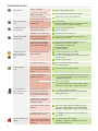
CAME LZR-I100 LZR-I110 Guida d'installazione
- Categoria
- Illuminazione di comodità
- Tipo
- Guida d'installazione

1
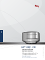
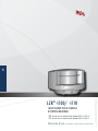
LZR®-I100/ -I110
EN
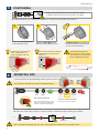
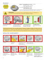
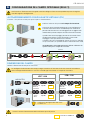
I100: max. detection range of 9.9 m x 9.9 m
I110: max. detection range of 5.0 m x 5.0 m
LASER SCANNERS FOR INDUSTRIAL DOORS
User’s Guide for software version 0600 and higher
This user’s guide is an informative document and
can not be seen as a commitment of result.

2
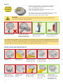
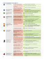
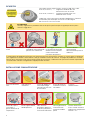
Avoid extreme
vibrations.
Do not cover
the front screens. Avoid moving objects
and light sources in
the detection field.
Avoid condensation.
Avoid the presence
of smoke and fog in
the detection field.
Avoid exposure to
sudden and extreme
temperature changes.
Keep the sensor
permanently powered
in environments where
the temperature can
descend below -10°C.
Wipe the front
screens regularly
with a clean and
damp cloth.
Do not use aggressive
products to clean
the front screens.
Avoid direct exposure
to high pressure
cleaning.
SAFETY
INSTALLATION AND MAINTENANCE
Do not stare into the
visible red laser beams.
The warranty is void if
unauthorized repairs are
made or attempted by
unauthorized personnel.
Only trained and qualified
personnel may install and
adjust the sensor.
The manufacturer of the door system is responsible for carrying out a risk assessment and installing the sensor and the
door system in compliance with applicable national and international regulations and standards on door safety. Other
use of the device is outside the permitted purpose and can not be guaranteed by the manufacturer. The manufacturer
cannot be held responsible for incorrect installations or inappropriate adjustments of the sensor.
Test the good functioning
of the installation before
leaving the premises.
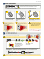
The device emits invisible (IR) and visible laser radiations.
IR laser: wavelength 905nm; output power <0.10mW
(Class 1 according to IEC 60825-1)
Visible laser: wavelength 635nm; output power <1mW
(Class 2 according to IEC 60825-1)
The visible laser beams are inactive during normal functioning.
The installer can activate the visible lasers if needed.
Do not stare into the visible red laser beams.
CAUTION!
Use of controls, adjustments or performance of procedures other than those specified herein
may result in hazardous radiation exposure.

3
CAT2
Pl d
1
2
3
4
5
6
8
10
9
7
1 2 3 4
CAT2
Pl d
1x
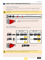
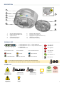
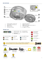
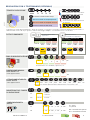
DESCRIPTION
SYMBOLS
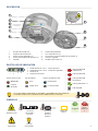
LED-SIGNAL
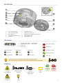
DETECTION LEDs
no detection
ERROR LED POWER LED
detection
no error
error
no power
power
Caution!
Laser radiation
LED flashes quickly
LED flashes
LED is off
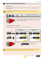
1. laser sweep emission
2. laser sweep reception
3. LED-signals (4)
4. screws for position lock (2)
5. connector
6. protection cover
7. visible laser beams (3)
8. notches for tilt angle adjustment (2)
9. adjustable bracket
10. cable conduits (4)
1. Detection LED: relay 1 - optional field
2. Detection LED: relay 2 - safety field
3. Error LED
4. Power LED
Remote control
sequence
Possible
remote control
adjustments
Factory
values
According
to
Not
according
to
LED flashes slowly
All 4 LEDs can be switched off and on again by remote control.
This can be useful in cases where the sensor should not draw any attention.
LED flashes once
Attention!
Important! Tip
Info

4
x
4x 2x
1x
3x
30’
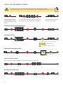
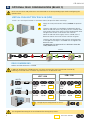
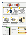
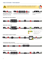
HOW TO USE THE REMOTE CONTROL
30 minutes after last use, the sensor locks the access to the remote control session.
Cut and restore power supply. The remote control session is accessible again during 30 minutes.
ADJUSTING ONE OR MORE PARAMETERS
CHECKING A VALUE
RESTORING TO FACTORY VALUES
SAVING AN ACCESS CODE
DELETING AN ACCESS CODE
The access code is recommended for sensors installed close to each other.
After unlocking, the red
LED flashes and the sensor
can be adjusted by remote
control.
If the red LED flashes quickly after unlocking, you
need to enter an access code from 1 to 4 digits.
= field width: 4.2 m
= field width is defined by teach-in
To end an adjustment session,
always lock the sensor.
Enter the existing code
teach-in
X = number of flashes = value of the parameter

5
123
45
1
2
10 cm
45°
LZR-I100/-110
45°
+
-
+
-
CAT2
Pl d
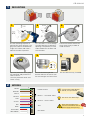
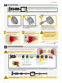
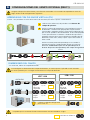
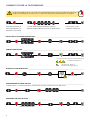
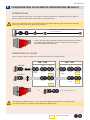
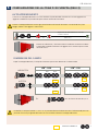
Door control without test:
connect red and blue wires to
power supply (with polarity)
Use the mounting template to
position the sensor correctly. The
grey area indicates the detection
range. Drill 4 holes and make a
hole for the cable if possible.
Pass the cable +/- 10 cm though
the cable opening. If drilling an
opening is not possible, use the
cable conduits on the back side
of the bracket.
Position the bracket and fasten
the 4 screws firmly in order to
avoid vibrations.
Position the housing on the
bracket and turn the sensor until
the two triangles are face to face.
MOUNTING
WIRING
POWER SUPPLY
RELAY 1 - OPTIONAL FIELD
RELAY 2 - SAFETY FIELD
TEST
NOT USED
GREEN
BROWN
WHITE
YELLOW
PINK
VIOLET
RED
BLUE
WHITE/RED
WHITE/BLUE
Open the protection cover, plug
the connector and position the
cable in the slit.
Close the protection cover and
fasten it firmly.
The sensor tests both relays.
Use the Power Supply Module
(24V DC, 0.75 A) if needed.
Use the LBA accessory if needed.

6
LZR-I100/-110
CAT2
Pl d
3
1 2
4
CAT2
Pl d
50 cm
5 m
94°
C1
left right left right
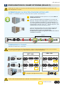
WITH BACKGROUND WITHOUT BACKGROUND
centre
MOUNTING SIDE
Check and select the corresponding mounting side if necessary.
Stay outside of the detection field to avoid disturbances.
The sensor memorizes the floor as
reference point and signals a fault
when its orientation is changed.
No reference point, no signal.
Adjust the lateral position
of the detection field.
Adjust the tilt angle of the
detection field with the hex key.
Lock the position of the mounting
bracket to avoid malfunctioning in
case of extreme vibrations.
Unlock the sensor and activate the visible laser beams
in order to position the curtains parallell to the door.
POSITIONING
The distance between the
inner curtains of the 2 sensors
must be max. 20 cm to ensure
safety according to EN12453.
After setting the mounting side, the safety and the optional field have the same dimensions.
The visible laser beams stay activated for 15 minutes or can be turned off by the same sequence.
A teach-in is launched, the sensor learns its environment and automatically determines the detection field(s).
Both RED LEDs flash slowly and the 3 visible laser beams automatically light up during 30 seconds.
teach-in
Ex:
The distances between the
curtains depend on the
mounting height and side.
The visible laser beams indicate
approximately the postion of
curtain C1.
C1

7
LZR-I100/-110
5
LZR®-I100 LZR®-I110
--
--
MIN MAX MIN MAX
0,5 m 9,9 m 0,5 m 5,0 m
5,0 m
0,1 m 9,9 m 0,1 m 5,0 m
5,0 m
FACTORY VALUES
SAFETY FIELD CONFIGURATION (RELAY 2)
3 s max. 30 s
Wait for the sensor to learn its environment
or lock it by remote control.
Launch a teach-in after changing the sensor position or when new objects are added to or changed in
the detection zone.
During teach-in, the detection field should be free of snow buildups, heavy rain, snowfall, fog or other
moving objects.
During teach-in, the sensor learns its surroundings and adapts the
detection field shape to these. Objects in the detection field will
be cut out.
WIDTH
HEIGHT
0.5 m 0.5 m 5.0 m
5.0 m
5.0 m
5.0 m
no field no field
Ex: for a field width of 6.2 m
FIELD DIMENSIONS
SAFETY FIELD TEACH-IN
After the teach-in, the field dimensions can be reduced by remote control.
The field is by default limited to 5 x 5 m. You can adapt the dimensions by remote control, but they
can never be bigger than the shape which was defined by the teach-in.

8
3
1
2
--
--
LZR-I100/-110
6
LZR®-I100 LZR®-I110
max 2x
0,5 m 9,9 m 0,5 m 5,0 m
0,5 m 9,9 m 0,5 m 5,0 m
0.5 m 9.9 m 0.5 m 5.0 m
0.5 m 9.9 m 0.5 m 5.0 m
no field no field
same as
safety
field
same as
safety
field
Install 1 or 2 virtual push buttons as activation zone(s) to open the door «manually».
Apply the vitual push button sticker(s) within the optional
field.
Launch a VPB teach-in to configure the detection zone(s).
When the red LED flashes very slowly after 3 seconds, hold
your hand in front of the sticker to learn the detection zone.
The green LED flashes 3x to confirm the selection.
When the red LED flashes again, learn a second (max. 2)
detection zone or wait until the LED switches to green.
Launch a new VPB teach-in each time the sensor position
is changed or new objects are added to or changed in the
detection zone.
ATTENTION! This VPB teach-in is different from the
safety field teach-in.
3 s
In order to configure the field dimensions, you have to cancel the virtual push button function by
launching a new VPB teach-in without any movement in the detection field.
Test the good functioning of the installation before leaving the premises.
FACTORY VALUES
OPTIONAL FIELD CONFIGURATION (RELAY 1)
WIDTH
HEIGHT
FIELD DIMENSIONS
VIRTUAL PUSH BUTTON TEACH-IN (VPB)
Make sure the white and yellow wires are connected to the corresponding inputs before configuring the
optional field.
Reduce the field dimensons if needed.
Change output configuration to value 3.

9
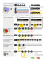
510 15 20 cm
cm
10 15 20 25
5
R1 R2
A - NO
P - NC
A - NOP - NC P - NC
A - NO
P - NCA - NO
LZR®-I100 max. max.
ms
100 200 300 400 500 600 700 800 900
XXXX
CAT2
Pl d
CAT2
Pl d
R1
R2
R1
R2
C1
C2
C3
C4
LZR®- I110
indoor outdoor
low
outdoor
med
outdoor
high indoor outdoor
low
outdoor
med
outdoor
high
R1
R2
R1
R2
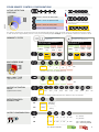
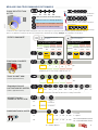
IMMUNITY FILTER
MIN. OBJECT SIZE
OUTPUT CONFIGURATION
DETECTION FIELD
REDIRECTION
(approximate values)
UNCOVERED ZONE
Increase in case of snow, dead leaves, etc.
optional
safety safety
optional
or safety
ACTIVE DETECTION
CURTAINS
off
The distances between the curtains depend on the mounting height and side. When mounted on the left, the distance between curtain
C1 and curtain C4 is approximately 10 cm for every meter (mounting height). Example: at 5 m the distance between C1 and C4 is 50 cm.
OUTPUT ACTIVATION
DEL AY
(approximate values) off
Ex:
C1 + C2 are active on safety field
C3 + C4 are active on optional field
C1 is active on both fields
C2+C3 are active on safety field
C4 is inactive
CURTAIN C1 C2 C3 C4
C1
C2
C3
C4
The relays are triggered when the detection duration ≥ the selected time.
curtain is inactive on both fields
curtain is active on optional field
curtain is active on safety field
curtain is active on both fields
All curtains are active on both fields
R = RELAY OUTPUT
A = active
P = passive
NO = normally open
NC = normally closed
OTHER REMOTE CONTROL CONFIGURATIONS
FOR CRITICAL ENVIRONMENTS
(RAIN SNOW, FOG) FOR CRITICAL OBJECTS
(DARK OBJECTS)
Recommended for
industrial doors applications
Recommended for Gates
applications

10
1
1
1
1
1
2
3
1
2
3
1
1
1
1
1
1
1
1
1
1
2
1
1
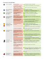
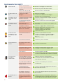
TROUBLESHOOTING
No blue LED
Only the blue LED
is on.
The detection LED
remains green.
The orange LED is
flashing and the
detection LEDs are
red.
The detection LED
remains red.
The orange LED
is on.
The sensor does
not respond to the
remote control.
The sensor does not
unlock.
There is no power.
The test input is not
connected.
The detection field is too
small or deactivated.
Someone or something is
in the detection field.
The field is touching the
floor, the wall or the door,
which leads to detection.
No background (reference
point) is found.
The sensor is masked.
The power supply voltage
is exceeding the acceptable
limits.
The sensor exceeds its
temperature limits.
Internal error
30 minutes after last use
of the remote control, the
sensor locks the access to
the remote control session.
The batteries in the remote
control are not installed
properly or dead.
The remote control is badly
pointed.
A reflective object is in close
proximity to the sensor.
You have to enter an access
code or the wrong code was
entered.
The object size is too small.
The polarity of the power
supply is inverted.
Check cable and connexion.
Check wiring.
The RED and BLUE cable have to be connected
to the test input or the power supply.
Check the size of the fields.
Launch a teach-in.
Step out of the field and/or remove the any
object(s) from the field.
Activate the 3 red beams and check if the
position of the sensor is correct.
If not, adjust the hex screws.
Verify the field size.
Launch a teach-in.
Check the position of the sensor.
Check the mounting side setting.
If there is no background, set the mounting side
to value 3 to 5.
Launch a new teach-in.
Verify and clean the front screens
with a damp cloth.
Check the power supply voltage.
Verify the outside temperature where the sensor
is installed. Eventually protect the sensor from
sunlight using a cover.
Wait a few seconds.
If the LED remains ON, reset the power supply.
If the LED turns on again, replace the sensor.
Cut and restore power supply.
The remote control session is accessible again
during 30 minutes.
Verify or replace the batteries.
Point the remote control towards the sensor,
but with a slight angle. The RC should not be
pointed in a right angle in front of the sensor.
Avoid highly reflective material in proximity to
the sensor.
Cut and restore power supply.
No code is required to unlock during the first
minute after powering.
Check the polarity of the power supply.
Decrease the min. object size.
All LEDs have been de-
activated by remote control.
Activate the LEDs by remote control.

11
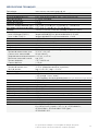
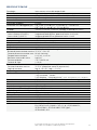
TECHNICAL SPECIFICATIONS
Specifications are subject to changes without prior notice.
All values measured in specific conditions.
Technology:
Detection mode:
Max. detection range:
Uncovered zone:
Remission factor:
Angular resolution:
Min. detected object size (typ.):
(in proportion to object distance)
Testbody:
Emission characteristics:
IR laser:
Red visible laser:
Supply voltage:
Power consumption:
Peak current at power-on:
Cable length:
Response time:
Output:
Max. switching voltage:
Max. switching current:
Switching time:
Output resistance:
Voltage drop on output:
Leakage current:
Input:
Max. contact voltage:
Voltage threshold:
Response time monitoring input:
LED-signal:
Dimensions:
Material:
Colour:
Mounting angles on bracket:
Rotation angles on bracket:
Tilt angles on bracket:
Protection degree:
Temperature range:
Humidity:
Vibrations:
Pollution on front screens:
Conformity:
laser scanner, time-of-flight measurement
motion and presence (EN 12453 level E)
LZR®-I100: 9.9 m x 9.9 m; LZR®-I110: 5.0 m x 5.0 m
5 - 25 cm (adjustable)
> 2 %
0,3516 °
LZR®-I100: 2,1 cm @ 3 m ; 3,5 cm @ 5 m ; 7 cm @ 10 m
LZR®-I110: 2,1 cm @ 3 m ; 3,5 cm @ 5 m
700 mm x 300 mm x 200 mm (testbody A according to EN 12453)
(IEC/EN 60825-1)
wavelength 905 nm; output power <0.10 mW (CLASS 1)
wavelength 635 nm; output power <1 mW (CLASS 2)
10-35 V DC @ sensor side (to be operated from SELV compatible power supplies only)
< 5 W
1.8 A (max. 80 ms @ 35 V)
10 m
typ. 20 ms; max. 80 ms (+ output activation delay)
2 electronic relays (galvanic isolated - polarity free)
35 V DC / 24 V AC
80 mA (resistive)
tON=5 ms; tOFF=5 ms
typ 30 Ω
< 0.7 V @ 20 mA
< 10 µA
2 optocouplers (galvanic isolated - polarity free)
35 V DC (over-voltage protected)
Log. H: >8 V DC; Log. L: <3 V DC
< 5 ms
1 blue LED: power-on status
1 orange LED: error status
2 bi-coloured LEDs: detection/output status (green: no detection; red: detection)
125 mm (D) x 93 mm (W) x 70 mm (H) (mounting bracket + 14 mm)
PC/ASA
black or white
-45 °, 0 °, 45 °
-5 ° to +5 ° (lockable)
-3 ° to +3 °
IP65
-30 °C to +60 °C if powered; -10 °C to +60 °C unpowered
0-95 % non-condensing
< 2 G
max. 30 %; homogenous
EN 12453 level E;
EN 12978; EN ISO 13849-1 CAT2, Pl “d”; IEC/EN 60825-1;
IEC/EN 61496-1; IEC/EN 61496-3 ESPE Type 2;
IEC/EN 62061 SIL 2

12
BEA SA | LIEGE SCIENCE PARK | ALLÉE DES NOISETIERS 5 - 4031 ANGLEUR [BELGIUM] | T +32 4 361 65 65 | F +32 4 361 28 58 | [email protected] | WWW.BEA-SENSORS.COM
©BEA | Original instructions | 42.7464 / V7 - 09.19
BEA hereby declares that the LZR®-I100/-I110 is in conformity with the European directives 2011/65/EU, 2014/30/EU and
2006/42/EC.
Notified Body for EC inspection: 0044 - TÜV NORD CERT GmbH, Langemarckstr. 20, 45141 D-Essen
EC-type examination certificate number: 44 205 13089629
Estelle Graas, Angleur, March 2019
The complete declaration of conformity is available on our website
This product should be disposed of separately from unsorted municipal waste
PLEASE KEEP FOR FURTHER USE
DESIGNED FOR COLOUR PRINTING

1
LZR®-I100/ -I110
ES
I100: rango máx. de detección de 9,9 m x 9,9 m
I110: rango máx. de detección de 5 m x 5 m
SOLUCIONES LÁSER ESCÁNER
PARA PUERTAS INDUSTRIALES
Guía del usuario
para la versión de producto 0600 y posteriores
This user’s guide is an informative document and
can not be seen as a commitment of result.

2
Evitar vibraciones
extremas.
No cubrir
las pantallas
frontales.
Evitar objetos en
movimiento y fuentes
luminosas en el
campo de detección.
Evitar la condensación.
Evitar la presencia de
humo y niebla en el
campo de detección.
Evitar la exposición
a cambios de
temperatura súbitos y
extremos.
Mantener el sensor
conectado permanentemente
a la fuente de alimentación
en entornos donde la
temperatura pueda alcanzar
valores inferiores a -10 °C.
Limpiar las
pantallas frontales
regularmente con
un paño húmedo y
limpio.
No utilizar productos
agresivos para limpiar
las pantallas frontales.
No limpiar
directamente con
equipos de limpieza a
alta presión.
SEGURIDAD
INSTALACIÓN Y MANTENIMIENTO
No mirar directamente a
los haces visibles del láser
de color rojo.
La garantía quedará anulada
si se realizan reparaciones
no autorizadas o por
personal no autorizado.
El sensor lo instalará y
ajustará exclusivamente
personal debidamente
formado y cualificado.
El fabricante del sistema de puertas será responsable de realizar una evaluación de riesgos y de instalar el sensor, así
como de asegurarse de que el sistema de puertas cumple los estándares y normativas nacionales e internacionales sobre
seguridad de puertas. Cualquier otro uso del dispositivo que no se contempla en la finalidad prevista, quedará excluido
de la garantía del fabricante. El fabricante declina toda responsabilidad por instalaciones o ajustes incorrectos del sensor.
Comprobar que la
instalación funciona
correctamente antes de
irse.
El dispositivo emite diodos láser IR invisibles y visibles.
Láser IR: longitud de onda = 905 nm
potencia de salida = <0.10mW
(Clase 1 según IEC 60825-1)
Láser visible: longitud de onda = 635 nm
potencia de salida = <1mW
(Clase 2 según IEC 60825-1)
Los haces visibles del láser están deshabilitados durante el funcionamiento
normal. El instalador puede activar los láseres visibles si es necesario.
PRECAUCIÓN
El uso de controles y la realización de ajustes o procedimientos distintos a los indicados en el
presente documento puede provocar la exposición a radiaciones peligrosas.

3
CAT2
Pl d
1
2
3
4
5
6
8
10
9
7
1 2 3 4
CAT2
Pl d
1x
DESCRIPCIÓN
SÍMBOLOS
PILOTOS LED DE INDICACIÓN
LED DE DETECCIÓN
ninguna
detección
LED DE ERROR LED DE ALIMENTACIÓN
detección
ningún error
error
sin alimentación
alimentación
Precaución
Radiación láser
Led parpadeando
rápidamente
Led parpadeando
Led apagado
1. emisión de barrido láser
2. recepción de barrido láser
3. Pilotos LED de indicación (4)
4. tornillo para bloqueo de posición (2)
5. conector
6. cubierta de protección
7. haz visible del láser (3)
8. ranura para ajuste de ángulo de inclinación (2)
9. montura regulable
10. conducto para cable (4)
1. Led de detección: relé 1 - campo opcional
2. Led de detección: relé 2 - campo de seguridad
3. Led de error
4. Led de alimentación
Secuencia
de mando a
distancia
Ajustes de
mando a
distancia
posibles
Valores de
fábrica
Conforme
a
No es
conforme
a
Led parpadeando
lentamente
Los cuatro pilotos LED pueden ser apagados y encendidos de nuevo mediante
el mando. Puede ser útil cuando el sensor no debe llamar la atención.
Led parpadeando 1 x
Cuidado!
Importante! Consejo
Información

4
x
4x 2x
1x
3x
30’
USO DEL MANDO A DISTANCIA
Transcurridos 30 minutos tras el último uso, el sensor bloquea el acceso a la sesión de mando a
distancia. Interrumpir y restablecer el suministro eléctrico. Al hacerlo, será posible acceder a la
sesión de mando a distancia durante 30 minutos.
AJUSTAR UNO O MÁS PARÁMETROS
COMPROBAR LOS VALORES
RESTABLECER LOS VALORES DE FÁBRICA
INTRODUCIR UN CÓDIGO DE ACCESO
ELIMINAR UN CÓDIGO DE ACCESO
Se recomienda el código de acceso para sensores instalados cerca de otros.
Tras el desbloqueo, el LED
rojo parpadea y es posible
ajustar el sensor por mando
a distancia.
Si el LED rojo parpadea rápidamente tras el
desbloqueo, será necesario introducir un código de
acceso de 1 a 4 dígitos.
x = número de destellos = valor del parámetro
= anchura de campo: 4,2 m
= anchura de campo definida mediante
el proceso de ajuste (aprendizaje)
Para finalizar la sesión de
ajuste, bloquear siempre el
sensor.
Introducir el código existente
aprendizaje

5
123
45
1
2
10 cm
45°
LZR-I100/-110
45°
+
-
+
-
CAT2
Pl d
Control de puerta sin test:
conectar los cables azul y rojo al
suministro eléctrico (con polaridad).
Usar la plantilla de montaje para
colocar el sensor correctamente. La
zona de color gris indica el rango de
detección. Perforar 4 agujeros en la
plantilla de montaje. Perforar, si es
posible, un agujero para el cable.
Pasar el cable +/- 10 cm a través
del agujero para el cable. Si no es
posible perforar un agujero, utilizar
los conductos para cables que hay
en la parte trasera de la montura.
Colocar la montura y apretar
los 4 tornillos con firmeza para
evitar posibles vibraciones.
Colocar la carcasa en la montura.
Girar el sensor hasta que los dos
triángulos queden enfrentados.
MONTAJE
CABLEADO
SUMINISTRO ELÉCTRICO,
POLO
RELÉ 1 -
CAMPO OPCIONAL
RELÉ 2 -
CAMPO DE SEGURIDAD
TEST
NO UTILIZADO
VERDE
MARRÓN
BLANCO
AMARILLO
ROSA
VIOLETA
ROJO
AZUL
BLANCO/ROJO
AZUL/BLANCO
Abrir la cubierta de protección,
enchufar el conector y pasar el
cable por la ranura.
Cerrar la cubierta de protección
y fijarla con firmeza.
El sensor prueba los dos relés.
Si es necesario, usar el módulo de
alimentación (24V DC, 0.75 A).
Usar el accesorio LBA si es
necesario.

6
LZR-I100/-110
CAT2
Pl d
3
1 2
4
CAT2
Pl d
50 cm
5 m
94°
C1
izquierda derecha izquierda derecha
CON FONDO SIN FONDO
centro
LADO DE MONTAJE
Permanecer fuera del campo de detección para evitar
perturbaciones.
El sensor hace un auto-aprendizaje de su entorno y determina el campo(s) de detección
automáticamente. Ambos led rojos parpadean lentamente y los 3 haces visibles del láser se iluminan
automáticamente durante 30 segundos.
El sensor memoriza el suelo
como punto de referencia
y envía una señal de fallo al
cambiar su orientación.
Sin punto de referencia no se
envía ninguna señal.
Ajustar la posición lateral
del campo de detección.
Ajustar el ángulo de inclinación
del campo de detección con la
llave hexagonal.
Bloquear la posición de la
montura para evitar fallos de
funcionamiento en caso de que se
produzcan vibraciones extremas.
Desbloquear el sensor y activar los haces visible del láser para
poder posicionar el campo de detección paralelamente a la puerta.
COLOCACIÓN
La distancia entre las cortinas
interiores de los 2 sensores
debe ser de 20 cm como máx.
para asegurar la seguridad en
conformidad la EN12453.
Los haces visibles del láser permanecen habilitados durante 15 minutos o, pueden deshabilitarse con el mando.
Si es necesario, verificar y seleccionar el lado de instalación.
La distancia entre las cortinas
depende de la altura de
instalación y del lado.
Los haces visibles indican
aproximadamente la posición de
C1 (la primera cortina).
Ej:
Después de haber seleccionado el lado de instalación, el campo de detección y el campo opcional tendrán
las mismas dimensiones.
aprendizaje
C1

7
LZR-I100/-110
5
LZR®-I100 LZR®-I110
--
--
MIN MAX MIN MAX
0,5 m 9,9 m 0,5 m 5,0 m
5,0 m
0,1 m 9,9 m 0,1 m 5,0 m
5,0 m
3 s 30 s máx.
Esperar a que el sensor "aprenda" su entorno
o bien, bloquearlo por mando a distancia.
CAMPO DE SEGURIDAD (RELAIS 2)
Realizar el proceso de ajuste (aprendizaje) tras cambiar la posición del sensor o al añadir/cambiar objetos en
la zona de detección.
ANCHURA
ALTURA
ningún
campo ningún
campo
El campo de detección no debe verse perturbado por acumulación de nieve, fuerte lluvia, nevadas, niebla u
objetos en movimiento.
Ej: para una anchura
de campo de 6,2 m
Durante el proceso de ajuste, el sensor aprende su entorno y adapta a
éste la forma del campo de detección. Los objetos que haya en el campo
de detección serán recortados.
APRENDIZAJE
VALORES DE FÁBRICA
Después del aprendizaje, el campo de detección puede ser reducido por mando.
DIMENSIONES DEL CAMPO
Por defecto, el campo de detección es limitado a 5 x 5 metros. Las dimensiones pueden ser adaptadas por
mando pero nunca podrán ser más grande que la forma definida durante el aprendizaje.

8
3
1
2
--
--
LZR-I100/-110
6
LZR®-I100 LZR®-I110
max 2x
0,5 m 9,9 m 0,5 m 5,0 m
0,5 m 9,9 m 0,5 m 5,0 m
APRENDIZAJE CON PULSADOR VIRTUAL (PV)
Instalar 1 ó 2 pulsadores virtuales como zona(s) de activación para abrir la puerta “manualmente”.
Asegurarse de que los cables blanco y amarillo están conectados a las entradas correspondientes antes de
elegir una de las dos configuraciones siguientes.
Colocar el(los) adhesivo(s) del pulsador virtual dentro del
campo de apertura.
Realizar el proceso de aprendizaje PV para configurar la zona(s)
de detección. Cuando el LED rojo parpadea muy lentamente
transcurridos 3 segundos, colocar la mano frente al adhesivo para
que el sensor aprenda la zona de detección. El LED verde parpadea
3 veces para confirmar la selección. Cuando el LED rojo vuelva a
parpadear, permitir que el sensor aprenda una segunda zona de
detección (2 zonas máx.) o bien, esperar a que el LED cambie su
color a verde.
Realizar un nuevo proceso de aprendizaje PV tras cambiar la
posición del sensor o al añadir/cambiar objetos en la zona de
detección. ATENCIÓN Este proceso de aprendizaje PV es
distinto del proceso de aprendizaje del campo de seguridad.
CONFIGURACIONES DEL CAMPO OPCIONAL (RELÉ 1)
ANCHURA
ALTURA
ningún
campo
ningún
campo
igual
que el de
seguridad
igual
que el de
seguridad
3 s
Comprobar que la instalación funciona correctamente antes de abandonar el lugar.
VALORES DE FÁBRICA
Para configurar las dimensiones del campo de detección, se necesita quitar el pulsador virtual lanzando
un nuevo aprendizaje PV sin ningún movimiento en el campo de detección.
DIMENSIONES DEL CAMPO
Si es necesario, reducir el campo de detección.
Cambiar la salida de configuración
por el valor «3».
La pagina si sta caricando...
La pagina si sta caricando...
La pagina si sta caricando...
La pagina si sta caricando...
La pagina si sta caricando...
La pagina si sta caricando...
La pagina si sta caricando...
La pagina si sta caricando...
La pagina si sta caricando...
La pagina si sta caricando...
La pagina si sta caricando...
La pagina si sta caricando...
La pagina si sta caricando...
La pagina si sta caricando...
La pagina si sta caricando...
La pagina si sta caricando...
La pagina si sta caricando...
La pagina si sta caricando...
La pagina si sta caricando...
La pagina si sta caricando...
La pagina si sta caricando...
La pagina si sta caricando...
La pagina si sta caricando...
La pagina si sta caricando...
La pagina si sta caricando...
La pagina si sta caricando...
La pagina si sta caricando...
La pagina si sta caricando...
-
 1
1
-
 2
2
-
 3
3
-
 4
4
-
 5
5
-
 6
6
-
 7
7
-
 8
8
-
 9
9
-
 10
10
-
 11
11
-
 12
12
-
 13
13
-
 14
14
-
 15
15
-
 16
16
-
 17
17
-
 18
18
-
 19
19
-
 20
20
-
 21
21
-
 22
22
-
 23
23
-
 24
24
-
 25
25
-
 26
26
-
 27
27
-
 28
28
-
 29
29
-
 30
30
-
 31
31
-
 32
32
-
 33
33
-
 34
34
-
 35
35
-
 36
36
-
 37
37
-
 38
38
-
 39
39
-
 40
40
-
 41
41
-
 42
42
-
 43
43
-
 44
44
-
 45
45
-
 46
46
-
 47
47
-
 48
48


CAME LZR-I100 LZR-I110 Guida d'installazione
- Categoria
- Illuminazione di comodità
- Tipo
- Guida d'installazione
in altre lingue
- español: CAME LZR-I100 LZR-I110 Guía de instalación
- português: CAME LZR-I100 LZR-I110 Guia de instalação
Documenti correlati
Altri documenti
-
 Lince 1962-SBP-M Istruzioni per l'uso
-
Marantec LZR-I110 Manuale del proprietario
-
Marantec LZR-H100 Manuale del proprietario
-
SICK WL4SL(G)-3 Photoelectric reflex sensor Istruzioni per l'uso
-
-
-
-
-
