McQuay IM-WMF-0501 Guida d'installazione
- Categoria
- Condizionatori d'aria a sistema split
- Tipo
- Guida d'installazione

WALL MOUNTED
SPLIT TYPE AIR CONDITIONER
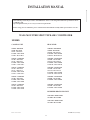
INSTALLATION MANUAL
Group: WALL MOUNTED
Part Number: A08019025515
Date: MAY 2001
IM-WMF-0501-McQuay
© 2001 McQuay International


i
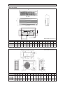
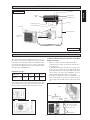
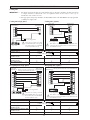
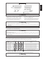
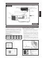
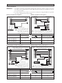
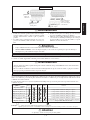
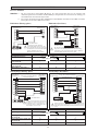
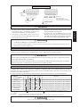
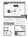
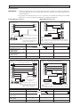
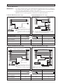
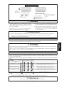
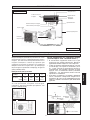
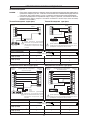
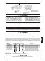
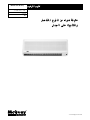
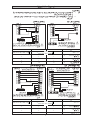
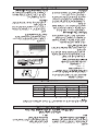
All dimensions are in mm / (in)
Indoor Unit (WM)
OUTLINE AND DIMENSIONS
A
B
Front View
Top View
Installation Plate
C
SideView
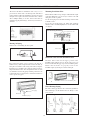
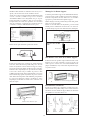
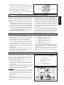
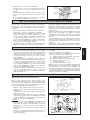
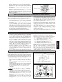
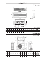
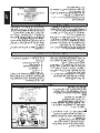
Outdoor Unit (SL-B Series)
A
D
F
N
O
M
K
L
J
I
B
E
H
G
I
FOR PIPE HOLE POSITION
IN THE WALL
HOLE O 65.0mm
FOR PIPE HOLE POSITION
IN THE WALL
HOLE O 65.0mm
CENTER
LINE
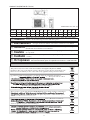
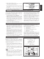
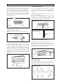
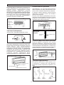
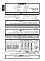
All dimensions are in mm / (in)
Dimension A B C D E F G H I J K L M N O
07 / 10 / 15F / FR 815 (32,1) 291 (11,4) 181 (7,1) 719 (28,3) 278 (10,9) 47 (1,9) 47 (1,9) 12 (0,5) 32 (1,3) 35(1,4) 302 (11,9) 342 (13,5) 100 (3,9) 118 (4,6) 172 (6,8)
20 / 25F / FR 1060 (41,7) 310 (12,2) 200 (7,9) 912 (35,9) 294 (11,6) 99 (3,9) 51 (2,0) 8 (0,3) 48 (1,9) 43 (1,7) 354 (13,9) 403 (15,9) 160 (6,3) 138 (5,4) 160 (6,3)
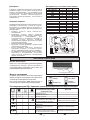
Dimension A B C D E F G H J K L M N P Q R
07B / 07BR
740 494 270 266 233 474 47 55 65 166 92 348 318 129 482 68,5
10B / 10BR
(29,1) (19,4) (10,6) (10,5) (9,2) (18,7) (1,9) (2,2) (2,6) (6,5) (3,6) (13,7) (12,5) (5,1) (19,0) (2,7)
15B / 15BR
20B / 20BR 840 646 330 297 309 626 41 85 75 177 106 408 378 124 592 78,5
25B / 25BR (33,1) (25,4) (13,0) (11,7) (12,2) (24,6) (1,6) (3,3) (3,0) (7,0) (4,2) (16,1) (14,9) (4,9) (23,3) (3,1)
Q
N
E
15 (0.6)
39 (1.5)
A
M
P
P
840 (33.1)
D
15 (0.6)
39 (1.5)
5 (0.2)
C
20 (0.8)
20 (0.8)
2.5 (0.1)
F
B
C
5 (0.2)
160 (6.3)
H
G
141 (5.6)
K
J
(2.6)
65
L
20 (0.8)
R

ii
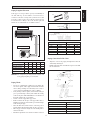
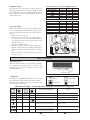
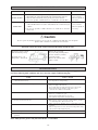
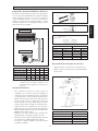
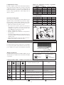
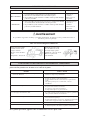
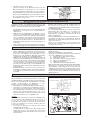
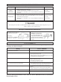
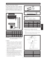
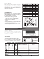
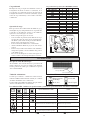
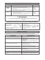
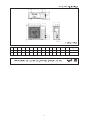
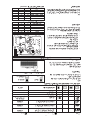
Outdoor Unit (SL071 & SL-C Series)
All dimensions are in mm / (in)
Dimension A B C D E F G H I J K L M N O
071 / 1R 600 (23,6) 475 (18,7) 245 (9,6) 418 (16,4) 177 (6,9) 35 (1,3) 93 (3,6) 81 (3,1) 83 (3,2) 55 (2,2) 398 (15,6) 101 (3,9) 97 (3,8) 17 (0,6) 22 (0,8)
10 / 15 C /CR 700 (27,5) 521 (20,5) 250 (9,8) 485 (19,1) 175 (6,8) 36 (1,4) 95 (3,7) 93 (3,6) 86 (3,3) 68 (2,6) 441 (17,3) 130 (5,1) 111 (4,3) 15 (0,5) 18 (0,7)
30
(1.2)
(0.1)
3
(0.7)
19
(2.6)
65
(3.1)
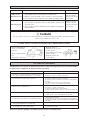
80
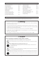
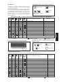
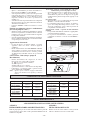
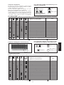
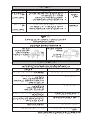
NOTICE
This product is subjected to Waste of Electrical and Electronic Equipment Regulations (WEE
E
Regulations). The waste product shall be separately collected by specific collection and treatment centre
.
P
lease refer to local authorithy for these centres. This is only applicable to European Union countries
.
Ce produit est soumis
à
la r
à
é
r
r
glementation concernant les
d
é
chets
d
es
é
quipements
é
lectriques e
t
é
lectroniques (r
é
r
r
é
ê
é
s
é
par
é
r
r
m
ent par un centre de collect
e
é
é
é
î
î
tre ces centres. Ceci
îî
é
enne
.
Questo prodotto
è
soggetto alle disposizioni RAEE (Rifiuti di apparecchiature elettriche ed elettroniche)
.
à
à
locali. Questa disposizione
à
è
valida solamente i paes
i
d
el
l
’
U.
E
.
é
ctrico y Electr
ó
n
ico en materia d
e
ñ
ñ
á
í
fico
í
í
de colecc
i
ó
solamente aplicable a los p
a
í
ses de la
U
n
i
ó
n
Europea
.
G
er
ä
ä
ä
tes
ää
getrennt vom Hausm
ü
ll bei Ihrer
ö
r
tlichen
M
ü
lldeponie bzw. Ihrem
ö
r
tliche
n
ä
ndiges Abfall-Amt. Dieser
ää
Hinweis gilt nur f
ü
f
f
rL
ä
nder der Europ
ää
ä
ischen Union
.
п
р
авилам
и
п
о
у
тилизаци
и
отхо
д
о
в
(WEEE Re
g
ulations).
и
.
,
.
Э
т
и
п
р
авил
а
Ев
р
опейског
о
.
Per preservarsi da eventuali ferite, evitare di toccare gli spigoli affilati e la superficie
dei serpentini.
! Cautela
Острые края и поверхности змеевиков являются потенциальными
местами нанесения травм. Остерегайтесь контакта с этими местами.
! Осторожно
Sharp edges and coil surfaces are potential locations which may cause injury
hazards. Avoid from being in contact with these places.
! Caution
Les bords coupants et les surfaces du refroidisseur tubulaire présentent
un risque de blessure. Mieux vaut éviter le contact avec ces endroits.
!
Avertissement
Scharfe Kanten und Wärmetauscherflächen stellen eine Gefahrenquelle dar. Jeglicher
Kontakt mit diesen Stellen ist zu vermeiden.
! Vorsicht
Los Bordes afilados y la superficie del serpentín pueden producir lesiones. Evite
tocarlos.
! Cuidado
NCN
KLL
M
A
D
B
EF
IJ
GH
C

1-1
English
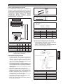
This manual provides the procedures of installation to ensure a safe and good standard of operation for the air
conditioner unit.
Special adjustment may be necessary to suit local requirements.
Before using your air conditioner, please read this instruction manual carefully and keep it for future reference.
INSTALLATION MANUAL
WALL MOUNTED SPLIT TYPE AIR CONDITIONER
MODEL
COOLING UNIT
WM07F / MWM007F
SL07B / MLC007B
SL071 / MLC007C
4SL07B / M4LC007B
5SL071 / M5LC007C
WM10F / MWM010F
SL10B / MLC010B
SL10C / MLC010C
4SL10B / M4LC010B
5SL10C / M5LC010C
WM15F / MWM015F
SL15B / MLC015B
SL15C / MLC015C
4SL15B / M4LC015B
5SL15C / M5LC015C
WM20F / MWM020F
SL20B / MLC020B
4SL20B / M4LC020B
5SL20B / M5LC020B
WM25F / MWM025F
SL25B / MLC025B
4SL25B / M4LC025B
5SL25B / M5LC025B
Part No.:A08019025515
HEAT PUMP
WM07FR / MWM007FR
SL07BR / MLC007BR
SL071R / MLC007CR
4SL07BR / M4LC007BR
5SL071R / M5LC007CR
WM10FR / MWM010FR
SL10BR / MLC010BR
SL10CR / MLC010CR
4SL10BR / M4LC010BR
5SL10CR / M5LC010CR
WM15FR / MWM015FR
SL15BR / MLC015BR
SL15CR / MLC015CR
4SL15BR / M4LC015BR
5SL15CR / M5LC015CR
WM20FR / MWM020FR
SL20BR / MLC020BR
4SL20BR / M4LC020BR
WM25FR / MWM025FR
SL25BR / MLC025BR
4SL25BR / M4LC025BR
INVERTER HEAT PUMP UNIT
WMV10FR / MWMV010FR
SLV10BR / MLCV010BR
WMV15FR / MWMV015FR
SLV15BR / MLCV015BR
IM-WMF-0501 (2) - McQuay

1-2
CONTENTS
Before installing the air conditioner unit, please read the following safety precautions carefully.
SAFETY PRECAUTIONS
! Warning
• Installation and maintenance should be performed by qualified persons who are familiar with local code and
regulation, and experienced with this type of appliance.
• All field wiring must be installed in accordance with the national wiring regulation.
• Ensure that the rated voltage of the unit corresponds to that of the name plate before commencing wiring work
according to the wiring diagram.
• The unit must be GROUNDED to prevent possible hazards due to insulation failure.
• All electrical wiring must not touch the refrigerant piping, compressor or any moving parts of the fan motors.
• Confirm that the unit has been switched OFF before installing or servicing the unit.
- Outline And Dimensions page i-ii
- Safety Precautions page 2
- Installation Diagram page 3
- Installation Of The Outdoor Unit page 3
- Installation Of The Indoor Unit page 4
- Refrigerant Piping page 5
- Electrical Wiring Connection page 6
- Special Precautions When Dealing
with R410A Unit page 7
- Special Precautions When Dealing
with R407C Unit page 7
! Caution
Please take note of the following important points when installing.
• Do not install the unit where leakage of flammable gas may occur.
If gas leaks and accumulates around the unit, it may cause fire ignition.
• Ensure that the drainage piping is connected properly.
If the drainage piping is not connected properly, it may cause water leakage which will dampen the
furniture.
• Do not overcharge the unit.
This unit is factory pre-charged. Overcharge will cause over-current or damage to the compressor.
• Ensure that the units panel is closed after service or installation.
Unsecured panels will cause the unit to operate noisily.
- Vacuuming and Charging page 7
- Indicator Lights page 8
- Air Conditioner Unit Operation page 10
- Standard Operating Conditions page 10
- Electrostatic Filter page 10
- Auto Random Re-Start Function page 11
- Phase Protector (Optional) page 11
- Service And Maintenance page 12
- Troubleshooting page 12

1-3
English
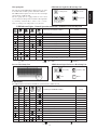
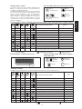
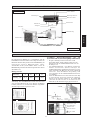
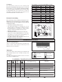
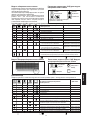
INSTALLATION DIAGRAM
Indoor Unit
Refrigerant Piping
SLC
Air Discharge
Nozzle
Air Intake
Air
Intake
Drain Hose
Signal
Receiver
Indicator
Lights
Air Intake
Grille
Back Housing
ON/OFF Switch
Front Frame
Air Filters
Air Discharge Louver
Air Discharge Grille
Air Intake
Air Discharge
Nozzle
Outdoor Unit
SLB
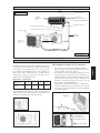
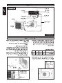
Dimension A B C D
Minimum mm 300 1000 300 500
Distance, (in) (11.8) (39.4) (11.8) (19.7)
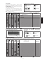
INSTALLATION OF THE OUTDOOR UNIT
The outdoor unit must be installed in such a way, so as to
prevent short circuit of the hot discharged air or obstruction
to the smooth air flow. Please follow the installation clear-
ance shown in the figure. Select the coolest possible place
where intake air temperature is not greater than the outside
air temperature (maximum 45°C).
Installation clearance
Note: If there is any obstacle higher than 2m, or if there is
any obstruction at the upper part of the unit, please allow
more space than the figure indicated in the above table.
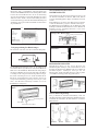
Condensed Water Disposal of Outdoor Unit (Heat
Pump Unit Only)
• There are 2 holes on the base of Outdoor Unit for
condensed water to flow out. Insert the drain elbow to
one of the holes.
• To install the drain elbow, first insert one portion of the
hook to the base (portion A), then pull the drain elbow
in the direction shown by the arrow while inserting the
other portion to the base. After installation, check to
ensure that the drain elbow clings to base firmly.
• If the unit is installed in a snowy and chilly area, con-
densed water may freeze in the base. In such case, please
remove plug at the bottom of unit to smooth the drain-
age.
Obstacle
Return Air
Service
Access
Obstacle
Obstacle
Return Air
Discharge Air
Obstacle
Please remove side
plate when connect-
ing the piping and
connecting cord
PUSH & PULL UP
BASE
A
DRAIN
ELBOW
DRAIN
ELBOW
PLUG
A
B
C
D

1-4
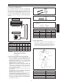
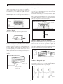
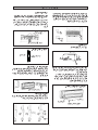
INSTALLATION OF THE INDOOR UNIT
Mounting Installation Plate
Ensure that the wall is strong enough to withstand the weight
of the unit. Otherwise, it is necessary to reinforce the wall
with plates, beams or pillars.
Use the level gauge for horizontal mounting, and fix it with
4 suitable screws.
In case the rear piping draws out, drill a hole 65mm in
diameter with a cone drill, slightly lower on the outside wall
(see figure).
Mount The Unit Onto The Installation Plate
Hook the indoor unit onto the upper portion of the
installation plate (Engage the two hooks at the rear top of
the indoor unit with the upper edge of the installation plate).
Ensure that the hooks are properly seated on the
installation plate by moving it to the left and right.
Water Drainage Piping
The indoor drain pipe must be in a downward gradient for
smooth drainage. Avoid situations that are likely to cause
water to leak.
End
Dipped
Into
Water
Water
Leaking
Water
Leaking
Water
Leaking
The indoor unit must be installed in such a way so as to
prevent short circuit of the cool discharged air with the hot
return air. Please follow the installation clearance shown in
the figure. Do not place the indoor unit where there could be
direct sunlight shining on it. Also, this location must be
suitable for piping and drainage, and be away from doors or
windows.
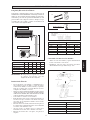
Routing Of Piping
Remove the screw holding the front panel.
Maintenance &
Servicing Space
Air Flow
Direction
Higher Than
Eye Level
The refrigerant piping can be routed to the unit in a
number of ways (left or right from the back of the unit), by
using the cut-out holes on the casing of the unit (see figure).
Bend the pipes carefully to the required position in order to
aligned it with the holes. For the right hand and rear side
out, hold the bottom of the piping and then position it to the
required direction (see figure). The condensation drain hose
can be taped to the pipes.
Wrong
Wrong
Wrong
Correct
Drain
Water Drainage
1
2
3
4
5
Piping Routing
Right & Rear Side Routing
Drain hose
Fix with vinyl tape
Unit piping
1. Hook the unit onto the installation plate.
Hole With Cone Drill
Indoor Side
Outdoor Side
Plate Mounting Installation
Screw position in the wall
Ø 65.0 mm Hole in the wall

1-5
English
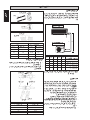
Piping Length & Elevation
If the pipe is too long, both the capacity and reliability of
the unit will drop. As the number of bends increases,
resistance to the flow of refrigerant system increases, thus
lowering cooling capacity. As a result, the compressor may
become defective. Always choose the shortest path and
follow the recommendations as tabulated below:
REFRIGERANT PIPING
Outdoor Unit
Indoor Unit
HL
Remove Burr
Cutting Copper Tube
Piping Works
• Do not use contaminated or damaged copper tubing. Do
not remove plastic, rubber plugs and brass nuts from the
valves, fittings, tubings and coils until you are ready to
connect suction or liquid line into valves or fittings.
• If any brazing work is required, ensure that the nitrogen
gas is passed through coil and joints while the brazing
work is being done. This will eliminate soot formation on
the inside walls of the copper tubings.
• Cut the connection pipe with a pipe cutter.
• Remove burrs from cut edges of the pipes with remover.
Hold the end of the pipe downwards to prevent metal chips
from entering the pipe.
• Insert the flare nuts, mounted on the connection parts of
both the indoor unit and outdoor unit onto the copper pipes.
• Flare the pipe with extra length above the flaring tool as
shown in the table.
• The flared edge must be even and not cracked or scratched.
1/4t
Copper Tube
Swaging Block
Ø Tube, D A (mm)
Inch mm Imperial Rigid
1/4" 6.35 1.3 0.7
3/8" 9.52 1.6 1.0
1/2" 12.70 1.9 1.3
5/8" 15.88 2.2 1.7
3/4" 19.05 2.5 2.0
Piping Connection To The Units
• Align the center of the piping and tighten the flare nut
sufficiently with fingers.
• Finally, tighten the flare nut with the torque wrench until
the wrench clicks.
Pipe Size mm / (in) Torque Nm / (ft - lb)
6.35 (1/4) 18(13.3)
9.53 (3/8) 42(31.0)
12.7 (1/2) 55(40.6)
15.88 (5/8) 65(48.0)
19.05 (3/4) 78(57.6)
Indoor Piping
Flare Nut
Flared Tube
Flare Joint
Spanar
Torque Wrench
Remark: The refrigerant pre-charged in the outdoor unit
is for piping length up to 7.62 m/25 ft.
Model
Maximum length, m (ft), L
Max. elevation, m (ft), H
Max. number of bends
Liquid pipe size
Gas pipe size
07 10 15 20 25
12 (39) 12 (39) 12 (39) 15 (49) 15 (49)
5 (16.4) 5 (16.4) 5 (16.4) 8 (26.2) 8 (26.2)
10 10 10 10 10
1/4" 1/4" 1/4" 1/4" 3/8"
3/8" 3/8" 1/2" 5/8" 5/8"

1-6
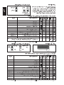
ELECTRICAL WIRING CONNECTION
Cooling unit
IMPORTANT : * The figures shown in the table are for information purpose only. They should be checked and selected
to comply with the local/national codes of regulations. This is also subject to the type of
installation and conductors used.
** The appropriate voltage range should be checked with label data on the unit. ETL listed is only applicable
to 60Hz power supply only.
COMP
N2
COMP
N
N1
L
Outdoor Unit
Terminal Block
Indoor Unit
Terminal Block
There must be a double pole switch
with a minimum 3mm contact gap and
fuse/circuit breaker as recommended
in the fixed installation circuit.
!
Power Supply Cable
!
There must be a double pole switch with a minimum 3mm
contact gap and fuse/circuit breaker as recommended in the
fixed installation circuit.
Terminal Block
Outdoor Unit
Indoor Unit
Terminal Block
N2
COMP
N1
L
COMP
N
L
T
N
S
R
Power Supply Cable
!
There must be a double pole switch
with a minimum 3mm contact gap and
fuse/circuit breaker as recommended in
the fixed installation circuit.
Outdoor Unit
Terminal Block
Indoor Unit
Terminal Block
Power Supply Cable
Outdoor coil sensor connection wire
(8m long) attached in the indoor unit
COMP
N2
OF
4WV
N1
L
COMP
OF
4WV
N
Model 07 / 10 / 15 20 / 25 20 / 25
Voltage range** 220V-240V / 1Ph / 50Hz +
380V-415V / 3Ph / 50Hz + N+
or 208V-230V / 1Ph / 60Hz+
Power supply cable size* mm
2
1.5 2.5 1.5
Number of wire 33 5
Interconnection cable size* mm
2
1.5 2.5 1.5
Number of wire 33 4
Recommended Fuse A 15 20 15
Outdoor Unit
Terminal Block
Indoor Unit
Terminal Block
Power Supply Cable
Outdoor coil sensor connection wire
(8m long) attached in the indoor unit
COMP
N2
OF
4WV
N1
L
COMP
OF
4WV
N
L
T
N
S
R
!
There must be a double pole switch with a minimum 3mm
contact gap and fuse/circuit breaker as recommended in the
fixed installation circuit.
Heat pump unit (single phase) Heat pump unit (3 phase)
Cooling unit (single phase) Cooling unit (3 phase)
Model 07 / 10 / 15 20 / 25 20 / 25
Voltage range** 220V-240V / 1Ph / 50Hz +
380V-415V / 3Ph / 50Hz + N+
or 208V-230V / 1Ph / 60Hz+
Power supply cable size* mm
2
1.5 2.5 1.5
Number of wire 33 5
Interconnection cable size* mm
2
1.5 2.5 1.5
Number of wire 55 6
Recommended Fuse A 15 20 15

1-7
English
• All wires must be firmly connected.
• All wires must not touch the refrigerant piping, compressor
or any moving parts of the fan motor.
• The connecting wires between the indoor unit and the
outdoor unit must be clamped on the wire clamps as shown
in the figure.
• The power supply cord must be equivalent to H05RN-F
(245IEC57) which is the minimum requirement.
SPECIAL PRECAUTIONS WHEN DEALING WITH R410A UNIT
R410A is a new HFC refrigerant which does not damage the
ozone layer. The working pressure of this new refrigerant is
1.6 times higher than conventional refrigerant (R22), thus
proper installation / servicing is essential.
• Never use refrigerant other than R410A in an air condi-
tioner which designed to operate with R410A.
• POE oil is used as lubricant for R410A compressor, which
is different from the mineral oil used for R22 compressor.
During installation or servicing, extra precaution must be
taken not to expose the R410A system too long to moist
air. Residual POE oil in the piping and components can
absorb moisture from the air.
• To prevent mischarging, the diameter of the service port
on the flare valve is different from that of R22.
SPECIAL PRECAUTIONS WHEN DEALING WITH R407C UNIT
• R407C is a zeotropic refrigerant mixture which has zero
ozone depletion potential and thus conformed to the
Montreal Protocol regulation. It requires Polyol ester oil
(POE) oil for its compressor's lubricant. Its refrigerant
capacity and performance are about the same as the
refrigerant R22.
• POE oil is used as lubricant for R407C compressor, which
is different from the mineral oil used for R22 compressor.
During installation or servicing, extra precaution must be
taken not to expose the R407C system too long to moist
air. Residual POE oil in the piping and components can
absorb moisture from the air.
• Refrigerant R407C is more easily affected by dust of
moisture compared with R22, make sure to temporarily
cover the ends of the tubing prior to installation.
• Use tools and materials exclusively for refrigerant R410A.
Tools exclusively for R410A are manifold valve, charging
hose, pressure gauge, gas leak detector, flare tools, torque
wrench, vacuum pump and refrigerant cylinder.
• As an R410A air conditioner incurs higher pressure than
R22 units, it is essential to choose the copper pipes cor-
rectly. Never use copper pipes thinner than 0.8mm even
though they are available in the market.
• If the refrigerant gas leakage occurs during installation /
servicing, be sure to ventilate fully. If the refrigerant gas
comes into contact with fire, a poisonous gas may occur.
• When installing or removing an air conditioner, do not
allow air or moisture to remain in the refrigerant cycle.
• No additional charge of compressor oil is permitted.
• No other refrigerant other than R407C.
• Tools specifically for R407C only (must not be used for
R22 or other refrigerant)
i) Manifold gauge and charging hose
ii) Gas leak detector
iii) Refrigerant cylinder/charging cylinder
iv) Vacuum pump c/w adapter
v) Flare tools
vi) Refrigerant recovery machine
• Filter-dryer must be installed along the liquid line for all
R407C air conditioners. This is to minimise the contamination
of moisture and dirt in the refrigerant system. Filter-dryer
must be of molecular sieve type. For a heat-pump system,
install a two-way flow filter dryer along the liquid line.
Wire Clamp
Interconnection
Cable
Power Supply
Cable
VACUUMING AND CHARGING
Purging the piping and the indoor unit
Except for the outdoor unit which is pre-charged with
refrigerant, the indoor unit and the refrigerant
connection pipes must be air-purged because the air
containing moisture that remains in the refrigerant cycle may cause
malfunction of the compressor.
•
Remove the caps from the valve and the service port.
•
Connect the center of the charging gauge to the vacuum pump.
•
Connect the charging gauge to the service port of the
3-way valve.
•
Start the vacuum pump. Evacuate for approximately
30 minutes. The evacuation time varies with different vacuum
pump capacity. Confirm that the charging gauge needle has
moved towards -760mmHg.
Caution
If the gauge needle does not move to -760mmHg, be sure to
check for gas leaks (using the refrigerant
detector) at flare type connection of the indoor and outdoor unit
and repair the leak before proceeding to the next step.
•
Close the valve of the changing gauge and stop the vacuum
pump.
•
On the outdoor unit, open the suction valve (3 way) and liquid
valve (2 way) (in anti-clockwise direction) with 4mm key for
hexagon sacked screw.
Service Port
Outdoor Unit
3 ways valve
Flare nut
Refrigerant
Piping
Allen key
Suction
valve
Discharge
Valve
Indoor Unit
Outdoor Unit
Liquid side
Gas side
Vacuum
pump
Open
Close
Close
Close
Hi
Low

1-8
Model
07F / 10F/ 15F
20F
25F
07FR / 10FR / 15FR
20FR
25FR
10m/32.8ft 12m/39.4ft 15m/49.2ft
35 65 –
35 65 110
90 165 280
50 90 –
60 110 185
120 220 370
Additional charge in gram (For R22/R407C models)
Open
Open
Suction
Valve
Discharge
Valvet
Indoor Unit
Outdoor Unit
Liquid side
Gas side
Check
Valve
Close
Hi
Low
Charge operation
This operation must be done by using a gas cylinder and a
precise weighing machine. The additional charge is topped-
up into the outdoor unit using the suction valve via the ser-
vice port.
• Remove the service port cap.
• Connect the low pressure side of the charging gauge to
the suction service port center of the cylinder tank and
close the high pressure side of the gauge. Purge the air
from the service hose.
• Start the air conditioner unit.
• Open the gas cylinder and low pressure charging valve.
• When the required refrigerant quantity is pumped into
the unit, close the low pressure side and the gas cylinder
valve.
• Disconnect the service hose from service port. Put back
the service port cap.
Model
07F / 10F/ 15F
20F
25F
07FR / 10FR / 15FR
20FR
25FR
10m/32.8ft 12m/39.4ft 15m/49.2ft
35 60 –
35 60 100
80 150 255
45 80 –
55 100 165
110 200 335
Additional charge in gram (For R410A models)
Additional charge
The refrigerant is pre-charged in the outdoor unit. If the
piping length is less than 7.62m (25ft), then additional charge
after vacuuming is not necessary. If the piping length is more
than 7.62m (25ft), then use the additional charge valve as
indicated in the table.
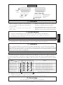
IR signal receiver
When an infrared remote control operating signal has
been transmitted, the signal receiver on the indoor unit
will make a <beep> sound to confirm acceptance of the
signal transmission.
Cooling unit
The table shows the LED indicator lights for the air condi-
tioner unit under normal operation and fault conditions.
The LED indicator lights are located at the bottom right
side of the air conditioner unit.
INDICATOR LIGHTS
LED indicator lights
IR Receiver
LED Indicator Lights for Cooling Unit
Timer
Sleep mode
Power ON
Dry mode
LED Indicator Lights : Normal Operation And Fault Conditions For Cooling Unit
Operation / Fault Indication Action
Timer on. –
Sleep mode on. –
Dry mode. –
Frost prevention. Clean the filter and switch to high fan.
Room air sensor contact loose/short. Call your dealer.
Indoor coil sensor contact loose/short. Call your dealer.
Sensor contact problem, compressor
overload protection trip or gas leak
Call your dealer.
Continuously
once every 2 sec.
twice every 2 sec.
3 times every 2 sec.
ON
ON or OFF Blinking

1-9
English
Heat pump unit
The table shows the LED indicator lights for the air condi-
tioner unit under normal operation and fault conditions.
The LED indicator lights are located at the bottom right
side of the air conditioner unit.
The heat pump units are equipped with an "auto" mode
sensor whereby it will provide reasonable room temperature
by switching automatically to either "cool" or "heat"
mode according to the temperature set by the user.
LED Indicator Lights For Heat Pump Unit
Cooling mode
Dry mode
Sleep mode
Heat / Fan mode
(red / green)
Cooling mode. –
Dry mode. –
Fan mode. –
Heat mode. –
Auto mode in heating operation. –
Auto mode in cooling operation. –
Defrost operation. –
Compressor overload protection. Call your dealer.
Indoor coil sensor contact loose /short. Call your dealer.
Outdoor coil sensor contact loose /short. Call your dealer.
Room air sensor contact loose /short. Call your dealer.
If the system is in cool mode or heat mode (with the sleep function off), the sensor
may have a contact problem, compressor overload protection trip or gas leak.
Normal Operation/Fault Condition
Action
Cool Dry Fan Heat Sleep
LED Indicator Lights : Normal Operation And Fault Conditions For Heat Pump Unit
ON ON or OFF Blinking
Inverter Heat Pump Unit
LED Indicator Lights For Inverter Heat Pump Unit
Cool / Dry
Stand-by / Fan
Timer
Heat
Cooling mode. –
Dry mode. –
Stand-by / Fan mode. –
Heat mode. –
Auto mode. –
Defrost operation. –
Compressor overload protection. Call your dealer.
Indoor temperature sensors contact loose / short. Call your dealer.
Outdoor temperature & current sensors contact loose / short. Call your dealer.
Gas leak / compressor overheat. Call your dealer.
Communication error between indoor and outdoor. Call your dealer.
Inverter error / PFC error. Call your dealer.
Outdoor total current trip / DC peak. Call your dealer.
Normal Operation/Fault Condition
Action
Cool Dry Heat Stand-by Timer
Green Red Red Red Green
LED Display
The LED in indoor and outdoor unit indicate operation modes / faults detected.
ON or OFF
ON
Blinking

1-10
Horizontal
Cooling
Dry
25°C / 77°F
STANDARD OPERATING CONDITIONS
Heat Pump Unit
Cooling unit
Temperature Ts °C / °F Th °C / °F
Minimum indoor
19.4 / 66.9 13.9 / 57.0
temperature
Maximum indoor
26.7 / 80.1 19.4 / 66.9
temperature
Minimum outdoor
19.4 / 66.9 13.9 / 57.0
temperature
Maximum outdoor
46 / 114.8 24 / 75.2
temperature
Ts: Dry bulb temperature. Th: Wet bulb temperature.
AIR CONDITIONER UNIT OPERATION
Dry mode
• When the air humidity is high, the unit can operate in
dry mode. Press <MODE> button and choose <DRY>.
• If the room temperature is 2°C/3.6°F higher than the set
temperature, the air conditioner will operate under
cooling mode until it reaches within the 2°C/3.6°F range
of difference compared to the set temperature before it
converts to dry mode.
• If the room temperature is within the 2°C/3.6°F range
of difference compared to the set temperature, it will
directly operate under dry mode.
• The unit will operate at LOW speed under dry mode.
Heat mode (for heat pump unit only)
• When the unit is switched on from cold start or
defrosting cycle, the indoor fan will start to operate only
after the coil reaches the desired temperature.
• When the set temperature is achieved, the indoor fan
will operate until the coil cannot provide anymore
additional heat.
Horizontal Air Flow Control
• For more effective air circulation, you can manually
adjust the air discharge grille to the left or right.
• During cool mode operation and dry mode operation,
do not direct the air discharge louver downwards for too
long. If operating continues in this way, condensation
may occur on the louver, thus resulting in drippings.
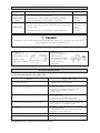
Hot Keep (for heat pump only)
• During compressor cut off, the indoor fan can be
switched to
(i) ON (default) or
(ii) OFF or
(iii) Interval on and off
by setting the slide switch shown in the diagram.
• The switch is located at the front frame cover (next to
the ON/OFF switch).
NOTE : When the option is selected, the power supply of
the unit need to be reset in order to activate the
function.
ON/OFF switch
HOT KEEP
OFF
INTERVAL
ON
Temperature Ts °C / °F Th °C / °F
Minimum indoor
10 / 50 –
temperature
Maximum indoor
26.7 / 80.1 –
temperature
Minimum outdoor
-8 / 17.6 -9 / 15.8
temperature
Maximum outdoor
24 / 75.2 18 / 64.4
temperature
Overheating protection (for heat pump unit only)
• In case the internal and/or the external temperature is to
high, or that the filter is dirty and clogged up, the
refrigerant may be overheated. The compressor will cut
out when the condensing temperature reaches 62°C/
143.6°F.
Frost prevention
• When the air filter is dirty, the evaporating temperature
will decrease and eventually cause frosting.
• The LED light will blink to indicate that the filter is
dirty. If the evaporating temperature reaches -1°C/33.8°F,
the unit will trip and defrost.
Fan speed and rated cooling capacity
• The rated cooling capacity is provided at the maximum
fan speed.
• The cooling capacity is lower when the unit is operating
at MEDIUM and LOW fan speed.
DUAL ACTION ELECTROSTATIC AIR PURIFYING
AND DEODORIZING FILTER MEDIA AND FILTER FRAME
ACTION 1-
ELECTROSTATIC AIR PURIFYING FILTER
Removes microscopic dust, smoke and small invisible
particles to keep the room air clean with pre-charged
electrostatic polypropylene filter.
ELECTROSTATIC FILTER
ACTION 2-
DEODORIZING FILTER
Removes unwanted smells and odors in the air and keeps
the room air fresh with activated carbon filter.

1-11
English
! Caution
1. The electrostatic air purifying and deodorizing filter
should be replaced once every 6 months or when the
filter changes color to brownish, whichever is sooner.
2. Used dusty filters should be disposed and shouldn't be
reused, even if it has been cleaned and washed.
3. The filter is a consumable part which you can purchase
from your air conditioner dealer.
4. Use the new filter immediately once it has been taken
out from its sealed packing. Do not unpack the new
filter too early before it is actually used as this may
decrease its deodorizing effect.
! Warning
• Disconnect from the main power supply before servicing the air conditioner unit.
• DO NOT pull out the power cord when the power is ON. This may cause serious electrical shocks which may result
in fire hazards.
AUTO RANDOM RE-START FUNCTION
If there is a power cut when the unit is operating, it will automatically resume the same operating mode when the power is
restored. (Applicable only to units with this feature.)
! Caution
Before turning off the power supply, set the remote controller’s ON/OFF switch to the “OFF” position to prevent the
nuisance tripping of the unit.
If this is not done, the unit’s fans will start turning automatically when power resumes, posing a hazard to service
personnel or the user.
HOW TO INSTALL
The unit with 3 phase Compressor can only rotate in one direction. For this reason, a protective device (phase protector) is
fitted to prevent incorrect wiring of the electrical phases. When the three phases are not connected correctly, the phase protector
operates, and the unit will not start. This devise is located in the control box of the outdoor unit.
The following table shows the LED indicator light for phase protector under normal operation and fault conditions.
PHASE PROTECTOR (OPTIONAL)
Normal operation
Reverse phase
T phase missing
S phase missing
R phase missing
S &T phase missing
+
Overload
+
Sensor missing
+
-
Switch off the unit. Check the 3 phase wiring.
Switch off the unit. Check the 3 phase wiring.
Switch off the unit. Check the 3 phase wiring.
Switch off the unit. Check the 3 phase wiring.
Switch off the unit. Check the 3 phase wiring.
High discharge temperature. Check the refrigerant system.
Switch off the unit. Plug in sensor.
LED
Description
PW
(Red)
P_R
(Yellow)
P_S
(Yellow)
P_T
(Yellow)
Actions
! Warning
• Trouble shooting must be performed by qualified personnel.
Notes : 1. “+” indicates additional functions for PP01 phase protector.
2.When R phase missing, no LED or buzzer will indicate the error, but relay 71 and relay 81 will cut off.
ON OFF Fast Blink

1-12
SERVICE AND MAINTENANCE
Maintenance Procedures
1. Remove any dust adhering to the filter by using a vacuum cleaner or wash in
lukewarm water (below 40°C/104°F) with a neutral cleaning detergent.
2. Rinse the filter well and dry before placing it back onto the unit.
3. Do not use gasoline, volatile substances or chemicals to clean the filter.
1. Clean any dirt or dust on the grille or panel by wiping it with a soft cloth
soaked in lukewarm water (below 40°C/104°F) and a neutral detergent
solution.
2. Do not use gasoline, volatile substances or chemicals to clean the
indoor unit.
Period
At least once
every 2 weeks.
More frequently if
necessary.
At least once
every 2 weeks.
More frequently if
necessary.
Service Parts
Indoor air filter
Indoor unit
! Caution
Do not operate any heating apparatus too close to the air conditioner unit. This may cause the plastic
panel to melt or deform as a result of the excessive heat.
When The Unit Is Not To Be Used For An Extended Long Period Of Time
Operate the unit for 2 hours
with the following setting.
Operating mode : cool
Temperature : 30°C/86°F
Remove the power plug.
If you are using an independent
electric circuit for your unit,
cut off the circuit.
Remove the batteries in the
remote control.
If any malfunction of the air conditioner unit is noted, immediately switch off the power supply to the unit.
Check the following fault conditions and causes for some simple troubleshooting tips.
TROUBLESHOOTING
Causes / Action
- Protection against frequent starting. Wait for 3 to 4 minutes for
the compressor to start operating.
- Power failure, or the fuse needs to be replaced.
- The power plug is disconnected.
- It is possible that your delay timer has been set incorrectly.
- If the fault persist after all these verifications, please
contact the air conditioner unit installer.
- The air filter is dirty.
- The doors or windows are open.
- The air suction and discharge are clogged.
- The regulated temperature is not high enough.
- Odors may be caused by cigarettes, smoke particles, perfume
etc. which might have adhered onto the coil.
- This is caused by air humidity after an extended long period of
operation.
- The set temperature is too low, increase the temperature setting
and operate the unit at high fan speed.
- Switch off unit and call dealer.
- Refrigerant fluid flowing into the evaporator coil.
Fault
1. The compressor does not operate 3 minutes after the air
conditioner unit is started.
2. The air conditioner unit does not operate.
3. The air flow is too low.
4. Discharge air flow has bad odor.
5. Condensation on the front air grille of the indoor unit.
6. Water flowing out from the air conditioner unit.
7. Hissing air flow sound from the air conditioner unit during
operation.
If the fault persists, please call your local dealer / serviceman.

English
2-1
Français
Ce manuel fournit les procédures d’installation pour assurer le bon fonctionnement et la sécurité de cet appareil.
Des ajustements peuvent être nécéssaires pour suivre les réglementations locales.
Avant d’installer et de faire fonctionner le climatiseur, lisez attentivement ce manuel et conservez le.
MANUEL D'INSTALLATION
CLIMATISEURS SPLIT SYSTEM MONTAGE MURAL
MODÈLE
FROID SEUL
WM07F / MWM007F
SL07B / MLC007B
SL071 / MLC007C
4SL07B / M4LC007B
5SL071 / M5LC007C
WM10F / MWM010F
SL10B / MLC010B
SL10C / MLC010C
4SL10B / M4LC010B
5SL10C / M5LC010C
WM15F / MWM015F
SL15B / MLC015B
SL15C / MLC015C
4SL15B / M4LC015B
5SL15C / M5LC015C
WM20F / MWM020F
SL20B / MLC020B
4SL20B / M4LC020B
5SL20B / M5LC020B
WM25F / MWM025F
SL25B / MLC025B
4SL25B / M4LC025B
5SL25B / M5LC025B
POMPE À CHALEUR
WM07FR / MWM007FR
SL07BR / MLC007BR
SL071R / MLC007CR
4SL07BR / M4LC007BR
5SL071R / M5LC007CR
WM10FR / MWM010FR
SL10BR / MLC010BR
SL10CR / MLC010CR
4SL10BR / M4LC010BR
5SL10CR / M5LC010CR
WM15FR / MWM015FR
SL15BR / MLC015BR
SL15CR / MLC015CR
4SL15BR / M4LC015BR
5SL15CR / M5LC015CR
WM20FR / MWM020FR
SL20BR / MLC020BR
4SL20BR / M4LC020BR
WM25FR / MWM025FR
SL25BR / MLC025BR
4SL25BR / M4LC025BR
UNITÉ DE POMPE À CHALEUR
D’INVERSEUR
WMV10FR / MWMV010FR
SLV10BR / MLCV010BR
WMV15FR / MWMV015FR
SLV15BR / MLCV015BR
Part No.:A08019025515 IM-WMF-0501 (2) - McQuay

2-2
SOMMAIRE
Avant de faire fonctionner l'appreil, veuillez bien lire les précautions de sécurité suivantes.
PRÉCAUTIONS DE SÉCURITÉ
! Attention
• L'installation et la maintenance doivent être exécutées par une personne qualifiée qui est familiarisée avec les lois
et réglementations en vigueur, et aussi expérimentée dans ce type d'équipements.
• Tous les câblages doivent répondre aux réglementations électriques nationales.
• Avant de commencer le raccordement suivant le schéma électrique, s’assurer que la tension nominale de l’appareil
corresponde bien à celle indiquée sur la plaque signalétique.
• L' unité doit être raccordée à la TERRE pour prévenir tous les risques possibles dûes à un défaut d'isolation.
• Aucun câble électrique ne doit toucher la tuyauterie du réfrigérant, le compresseur ou les pièces mobiles des moteurs
de ventilation.
• Avant l’installation ou l’entretien du climatiseur, s’assurer que l’appareil est éteint (OFF).
- Dimensions page i-ii
- Précautions de sécurité page 2
- Diagramme d’installation page 3
- Installation de l’unité extérieure page 3
- Installation de l’unité intérieure page 4
- Raccordement des tuyauteries page 5
- Raccordement électrique page 6
-
Précautions spéciales en traitant l’unité de R410A page 7
-
Précautions spéciales en traitant l’unité de
R407C page 7
! Avertissement
Vérifier les points suivants au cours de l’installation.
• Ne pas installer l'appareil où il peut se produire des fuites de gaz inflammable.
En cas de fuite et accumulation de gaz autour de l’appareil, il y a risque d’incendie.
• S’assurer que le tuyau d’évacuation du condensat est correctement branché.
Si le tuyau d’évacuation n’est pas correctement branché, les éventuelles fuites d’eau risquent de mouiller
le mobilier.
• Ne pas surcharger l'unité (en fluide frigorigène).
Cet appareil est préchargé en usine. Une charge trop importante risque de provoquer une surcharge
électrique ou d’endommager le compresseur.
• S’assurer que le panneau supérieur de l’appareil est remis en place après l’installation ou l’entretien.
Avec un panneau mal fixé l’appareil va fonctionner bruyamment.
- Aspiration et chargement page 7
- L’indicateur s’allume page 8
- Opération du climatiseur page 10
- Conditions standard de fonctionnement page 10
- Filtre électrostatique page 10
- Fonction de redemarrage au hasard automatique page 11
- Protecteur de phase (Facultatif) page 11
- Entretien ét maintenance page 12
- Analyse des causes de dysfonctionnement du
climatiseur page 12

English
2-3
Français
DIAGRAMME D’INSTALLATION
Unité Intérieure
Tuyauteries
Frigorifiques
SLC
Refoulement
d’air
Reprise
d'air
Reprise
d'air
Tuyau
D’evacuation
Led de
Visualisation
Récepteur
de Signal
Grilles de
Reprise d'air
Chassis Arriere
Interrupteur ON/OFF
Filtre à Air
Conduit de Ventilation
Grilles de Ventilation
Reprise
d'air
Refoulement
d’air
Unité Extérieure
SLB
Dimension A B C D
Minimum mm 300 1000 300 500
Distance, (pouce)
(11,8) (39,4) (11,8) (19.7)
INSTALLATION DE L’UNITÉ EXTÉRIEURE
L’unité extérieure (ou groupe de condensation) doit être
instalée dans un endroit où aucun obstacle ne doit perturber
la circulation de l’air, aussi bien à l’aspiration qu’au
refoulement du ventilateur (risque de recyclage d’air chaud).
Respecter les dégagements minimum prévus (voir tableau
ci-dessous). Choisir un emplacement le moins exposé
possible à l’ensoleillement; l’entré d’air sur l’unité extérieure
ne devra pas être supérieure à la température ambiante
(maximum 45°C).
Dégagements minimum
Remarques : En cas d’obstacles de part et d’autre de l’unité
d’une hauteur supérieure à 2 mètres ou toute obstruction d’air
sur le dessus de l’unité, augmenter sensibelment les
dégagements minimum prévus.
Disposition condensée de l'eau d'unité extérieure
(unité de pompe à chaleur seulement)
• Il y a 2 trous sur la base de l'unité extérieure pour que
l'eau condensée sorte. Insérez le coude de drain à un
des trous.
• Pour installer le coude de drain, première insertion une
partie du crochet sur la base (partie A), tirer alors le coude
de drain dans la direction montrée par la flèche tout en
insérant l'autre partie à la base. Après installation,
contrôle pour s'assurer que le coude de drain s'accrochent
à la base fermement.
• Si l'unité est installée dans un neigeux et chily un secteur,
l'eau condensée peut geler dans la base. Dans un tel cas,
enlevez svp la prise au fond de l'unité pour lisser le
drainage.
Veuillez enlever le
plat latéral en reliant
la tuyauterie et en
reliant la corde
POUSSEZ ET TIREZ VERS
LE HAUT
BASE
A
VIDANGEZ
LE
COUDE
VIDANGEZ
LE
COUDE
PRISE
Cadre Avant
Obstacle
Obstacle
Entrée d’air
Refoulement
Obstacle
Obstacle
Entrée d’air
Accès de service
AB
C
D

2-4
INSTALLATION DE L’UNITÉ INTÉRIEURE
Montage De La Platine Support
S’assurrer que le mur de support soit suffisamment résistant,
pour supporter le poids de l’unité et éviter toutes vibrations.
Selon la composition du mur, utiliser des vis chevilles
appropriées pour la fixation de la platine support.
Utiliser la jauge à niveau pour le montage horizontal, puis la
fixer avec 4 vis appropriées.
Dans le cas de sortie arrière des tuyauteries, percer le trou Ø
65mm pour les canalisations à l’aide d’une scie cloche. Le
trou aura une légère pente vers l’unité extérieure (Voir figure).
Mise En Place De L’unite De La Platine Support
Positionner dans un premier temps l’unité intérieure sur la
languette d’accrochage supérieure de support. Pour vous
assurer que les crochets sont correctement installés sur la
plaque d’installation, essayez de les faire légèrement bouger
de gauche à droite.
Évacuation Des Condensats
Le tube d’évacuation des condensats de l’unité devra être,
dans la mesure du possible, dirigé vers la sortie arriere des
tuyauteries a travers le mur de support. Evitez les situations
susceptibles de causer une fuite d’eau.
Evacuation
d’eau de
Conden-
sation
plongé
dans l’eau
Fuite
d’eau
Fuite
d’eau
Fuite
d’eau
Installer l’unité intérieure de traitement d’air de façon à ce
qu’il n’y ait aucun obstacle sur la circulation de l’air
(risque de recyclage de l’air refroidi au refoulement de l’unité
et l’air à l’entrée). Veuillez respecter l’écartement
d’installation illustré sur le diagramme. Ne pas exposer
l’unité intérieure à l’influence directe de l’éclairage.
L’emplacement de l’unité, doit permettre une évacuation
aisée des condensats, et permettre une evacuation aisee des
condensats, et doit être suffisamment loin des portes.
Orientation Des Tuyateries
Retirer les vis qui retiennent le panneau de devant.
Espace d’entretien et
de reparation
Direction de
la circulation
d’air
Plus naut
que le niveau
des yeux
L’unité d’évacuations des condensats de l’unité interieure
devra être, dans la mesure du possible, dirigé vers la sortie
arrière des tuyauteries à travers le mur de support (voir fig-
ure). Avant d’orienter le tubing, déclipser le support de tube.
Cintrer les tubes frigorifiques avec précaution et les diriger
vers la sorte choisie. Ne pas oublier de passer le câble
d’alimentation électrique dans l’unité intérieure à travers le
mur en même temps que les tuyauteries. Ne pas raccorder le
câble. Laisser une longueur de câble suffisante pour permettre
la connection ultérieure. Relier ensemble les tubes
frigorifiques, le flexible d’évacuation des condensats et le
câble électrique.
Incorrect
Incorrect
Incorrect
Correct
Drainage
Drainage De L’eau
1
2
3
4
5
Acheminement de la Tuyauterie
Acheminement de la Tuyauterie
Tuyau de drainage
Fixé avec ruban adhésif en vinyle
Tuyau de l’unité
1. Accrochez l’unité sur la plaque d’installation.
Trou Avec Perceuse En
Cône
Côté Intérieur
Côté Extérieur
Installation De La Plaque De Montage
Position de la vis dans le mur
Trou de 65,0mm de diamétre dans le mur
50,0mm
50,0mm
50,0mm
La pagina si sta caricando...
La pagina si sta caricando...
La pagina si sta caricando...
La pagina si sta caricando...
La pagina si sta caricando...
La pagina si sta caricando...
La pagina si sta caricando...
La pagina si sta caricando...
La pagina si sta caricando...
La pagina si sta caricando...
La pagina si sta caricando...
La pagina si sta caricando...
La pagina si sta caricando...
La pagina si sta caricando...
La pagina si sta caricando...
La pagina si sta caricando...
La pagina si sta caricando...
La pagina si sta caricando...
La pagina si sta caricando...
La pagina si sta caricando...
La pagina si sta caricando...
La pagina si sta caricando...
La pagina si sta caricando...
La pagina si sta caricando...
La pagina si sta caricando...
La pagina si sta caricando...
La pagina si sta caricando...
La pagina si sta caricando...
La pagina si sta caricando...
La pagina si sta caricando...
La pagina si sta caricando...
La pagina si sta caricando...
La pagina si sta caricando...
La pagina si sta caricando...
La pagina si sta caricando...
La pagina si sta caricando...
La pagina si sta caricando...
La pagina si sta caricando...
La pagina si sta caricando...
La pagina si sta caricando...
La pagina si sta caricando...
La pagina si sta caricando...
La pagina si sta caricando...
La pagina si sta caricando...
La pagina si sta caricando...
La pagina si sta caricando...
La pagina si sta caricando...
La pagina si sta caricando...
La pagina si sta caricando...
La pagina si sta caricando...
La pagina si sta caricando...
La pagina si sta caricando...
La pagina si sta caricando...
La pagina si sta caricando...
La pagina si sta caricando...
La pagina si sta caricando...
La pagina si sta caricando...
La pagina si sta caricando...
La pagina si sta caricando...
La pagina si sta caricando...
La pagina si sta caricando...
La pagina si sta caricando...
La pagina si sta caricando...
La pagina si sta caricando...
La pagina si sta caricando...
La pagina si sta caricando...
La pagina si sta caricando...
La pagina si sta caricando...
La pagina si sta caricando...
La pagina si sta caricando...
La pagina si sta caricando...
La pagina si sta caricando...
La pagina si sta caricando...
La pagina si sta caricando...
La pagina si sta caricando...
La pagina si sta caricando...
-
 1
1
-
 2
2
-
 3
3
-
 4
4
-
 5
5
-
 6
6
-
 7
7
-
 8
8
-
 9
9
-
 10
10
-
 11
11
-
 12
12
-
 13
13
-
 14
14
-
 15
15
-
 16
16
-
 17
17
-
 18
18
-
 19
19
-
 20
20
-
 21
21
-
 22
22
-
 23
23
-
 24
24
-
 25
25
-
 26
26
-
 27
27
-
 28
28
-
 29
29
-
 30
30
-
 31
31
-
 32
32
-
 33
33
-
 34
34
-
 35
35
-
 36
36
-
 37
37
-
 38
38
-
 39
39
-
 40
40
-
 41
41
-
 42
42
-
 43
43
-
 44
44
-
 45
45
-
 46
46
-
 47
47
-
 48
48
-
 49
49
-
 50
50
-
 51
51
-
 52
52
-
 53
53
-
 54
54
-
 55
55
-
 56
56
-
 57
57
-
 58
58
-
 59
59
-
 60
60
-
 61
61
-
 62
62
-
 63
63
-
 64
64
-
 65
65
-
 66
66
-
 67
67
-
 68
68
-
 69
69
-
 70
70
-
 71
71
-
 72
72
-
 73
73
-
 74
74
-
 75
75
-
 76
76
-
 77
77
-
 78
78
-
 79
79
-
 80
80
-
 81
81
-
 82
82
-
 83
83
-
 84
84
-
 85
85
-
 86
86
-
 87
87
-
 88
88
-
 89
89
-
 90
90
-
 91
91
-
 92
92
-
 93
93
-
 94
94
-
 95
95
-
 96
96


McQuay IM-WMF-0501 Guida d'installazione
- Categoria
- Condizionatori d'aria a sistema split
- Tipo
- Guida d'installazione
in altre lingue
- français: McQuay IM-WMF-0501 Guide d'installation
- español: McQuay IM-WMF-0501 Guía de instalación
Documenti correlati
-
McQuay G Series Guida d'installazione
-
McQuay A Series Guida d'installazione
-
-
McQuay MSD1020A Guida d'installazione
-
-
-
McQuay WH 11BR Istruzioni per l'uso
-
-
-
Altri documenti
-
Acson WM25GR Guida d'installazione
-
-
-
Haier 1U60IS1ERA Guida d'installazione
-
Haier 2U14CS2ERA Klimagerät Manuale del proprietario
-
-
-
-
Acson 5CEY15ER Guida d'installazione
-
Acson M-CCC-0501-ACSON Guida d'installazione