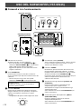
Yamaha NS-P610 Manuale del proprietario
- Categoria
- Subwoofer
- Tipo
- Manuale del proprietario

NS-P610
HOME CINEMA 5.1CH SPEAKER PACKAGE
5.1 SYSTEM D’ENCEINTES HOME CINEMA
OWNER’S MANUAL
MODE D’EMPLOI
BEDIENUNGSANLEITUNG
BRUKSANVISNING
MANUALE DI ISTRUZIONI
MANUAL DE INSTRUCCIONES
GEBRUIKSAANWIJZING
G B

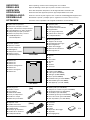
● Speaker cords
● Câbles d’enceintes
● Lautsprecheranschlußkabel
● Högtalarkabel
● Cavi per gli altoparlanti
● Cables de los altavoces
● Luidsprekerdraden
● Mounting brackets
● Supports de montage
● Befestigungshalterungen
● Monteringsfästen
● Staffe di montaggio
● Ménsulas de instalación
● Montagesteunen
● Screws
● Vis
● Schrauben
● Skruvar
● Viti
● Tornillos
● Schroeve
● Main and rear speakers
● Enceintes principales et arrière
● Haupt- und hinteres Lautsprecherpaar
● Huvudhögtalare och bakre högtalare
● Altoparlanti principali e posteriori
● Altavoces principales y traseros
● Hoofdluidsprekers en
achterluidsprekers
● Center speaker
● Enceinte centrale
● Centerlautsprecher
● Mitthögtalare
● Altoparlante centrale
● Altavoz central
● Middenluidspreker
● Subwoofer
● Subwoofer
● Subwoofer
● Subwooferhögtalaren
● Subwoofer
● Altavoz ultragraves
● Subwoofer
● Pin plug cord
● Câbles à fiches
● Cinch-Kabel
● Stiftkontakt-sladdar
● Cavo per altoparlante
● Cable con clavijas
● Kabel met pin-stekkers
● Speaker cords
● Câbles d’enceintes
● Lautsprecheranschlußkabel
● Högtalarkabel
● Cavi per gli altoparlanti
● Cables de los altavoces
● Luidsprekerdraden
UNPACKING After unpacking, check that the following items are included.
DEBALLAGE Après le déballage, vérifier que les pièces suivantes sont incluses.
AUSPACKEN Nach dem Auspacken überprüfen, ob die folgenden Teile vorhanden sind.
UPPACKNING Kontrollera efter det apparaten packats upp att följande delar finns med.
DISIMBALLAGGIO Verificare che tutte le parti seguenti siano contenute nell’imballaggio dell’apparecchio.
DESEMBALAJE Desembale el aparato y verifique que los siguientes accesorios están en la caja.
UITPAKKEN Controleer na het uitpakken of de volgende onderdelen voorhanden zijn.
[10m]
X 4
X 8
X 4
<NS-10MMT>
<NS-C10MM>
<YST-SW45>
[3m]
SUPERWOOFER SYSTEM YST-SW45
HIGH CUTSTANDBY/ON
150Hz50Hz
VOLUME
100
X 4
● Pads (for NS-10MMT)
● Patins (pour NS-10MMT)
● Auflagen (für NS-10MMT)
● Dynor (för NS-10MMT)
● Piedini di feltro (per l’NS-10MMT)
● Almohadillas (para NS-10MMT)
● Antislipplaatje (voor NS-10MMT)
● Rubber pads (for YST-SW45)
● Tampons en caoutchouc (pour YST-SW45)
● Gummiunterlagen (für YST-SW45)
● Gummidynor (för YST-SW45)
● Piedini di gomma (per l’YST-SW45)
● Forros de caucho (para YST-SW45)
● Anti-slip rubbers (voor YST-SW45)
● Fasteners
● Attaches
● Halter
● Fästen
● Dispositivo di fissaggio
● Sujetador
● Bevestigingsstrip
[4m]
X 3
X 2
X 4

English
E-1
●
To assure the finest performance, please read this manual
carefully. Keep it in a safe place for future reference.
●
Install the speakers in a cool, dry, clean place – away from
windows, heat sources, sources of excessive vibration, dust,
moisture and cold. Avoid sources of humming (transformers,
motors). To prevent fire or electric shock, do not expose the
speakers to rain or water.
●
To prevent the enclosure from warping or discoloring, do not
place the speakers where they will be exposed to direct sunlight
or excessive humidity.
●
Do not place the following objects on top of the speakers:
●
Other components, as they might cause damage and/or
discoloration on the surface of the speakers.
●
Burning objects (i.e. candles), as they might cause fire,
damage to the speakers and/or personal injury.
●
Containers with liquid in them, as they might cause electric
shock to the user and/or damage to the speakers.
●
Do not place the speakers where they are liable to be knocked
over or struck by falling objects. Stable placement will also
ensure better sound performance.
●
Placing the speakers on the same shelf or rack as the turntable
can result in feedback.
●
Secure placement or installation is the owner’s responsibility.
YAMAHA shall not be liable for any accident caused by improper
placement or installation of speakers.
●
Any time you note distortion, reduce the volume control on your
amplifier to a lower setting. Never allow your amplifier to be
driven into “clipping”. Otherwise the speakers may be damaged.
●
When using an amplifier with a rated output power higher than
the nominal input power of the speakers, care should be taken
never to exceed the speakers’ maximum input.
●
Do not attempt to clean the speakers with chemical solvents as
this might damage the finish. Use a clean, dry cloth.
●
Do not attempt to modify or fix the speakers. Contact qualified
YAMAHA service personnel when any service is needed. The
cabinet should never be opened for any reasons.
●
Be sure to read the “TROUBLESHOOTING” section regarding
common operating errors before concluding that the speakers
are faulty.
For YST-SW45 only
●
Do not operate this unit upside down. It may overheat, possibly
causing damage.
●
Do not use force on switches, controls or connection wires.
When moving this unit, first disconnect the power plug and the
wires connected to other equipments. Never pull the wires
themselves.
●
Since this unit has a built-in power amplifier, heat will radiate
from the rear panel. Place the unit apart from the walls, allowing
20 cm above, behind and on both sides of the unit to prevent fire
or damage. Furthermore, do not position with the rear panel
facing down on the floor or other surfaces.
●
To avoid condensation inside this unit, do not expose this unit to
sudden temperature changes from cold to hot, or do not place
this unit in an environment with high humidity (i.e. a room with a
humidifier). Condensation may cause an electric shock, fire,
and/or damage to this unit.
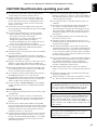
CAUTION: Read this before operating your unit.
Thank you for selecting this YAMAHA NS-P610 Speaker Package.
●
Do not cover the rear panel of this unit with a newspaper, a
tablecloth, a curtain, etc. in order not to obstruct heat radiation. If
the temperature inside this unit rises, it may cause fire, damage
to this unit and/or personal injury.
●
Do not plug in this unit to a wall outlet until all connections are
completed.
●
The voltage to be used must be the same as that specified on
the rear panel. Using this unit with a higher voltage than
specified is dangerous and may cause fire, damage to this unit,
and/or personal injury. YAMAHA will not be held responsible for
any damage resulting from use of this unit with a voltage other
than specified.
●
To prevent lightning damage, disconnect the AC power plug
when there is an electric storm.
●
Super-bass frequencies reproduced by this unit may cause a
turntable to generate a howling sound. In such a case, move this
unit away from the turntable.
●
This unit may be damaged if certain sounds are continuously
outputted at high volume level. For example, if 20 Hz–50 Hz sine
waves from a test disc, bass sounds from electronic instruments,
etc. are continuously outputted, or when the stylus of a turntable
touches the surface of a disc, reduce the volume level to prevent
this unit from being damaged.
●
If you hear distorted noise (i.e. unnatural, intermittent “rapping” or
“hammering” sounds) coming from this unit, reduce the volume
level. Extremely loud playing of a movie soundtrack’s low
frequency, bass-heavy sounds or similarly loud popular music
passages can damage this speaker system.
●
Vibration generated by super-bass frequencies may distort
images on a TV. In such a case, move this unit away from the TV
set.
●
When disconnecting the power cord from the wall outlet, grasp
the plug; do not pull the cord.
●
When not planning to use this unit for a long period (i.e. vacation,
etc.), disconnect the AC power plug from the wall outlet.
VOLTAGE SELECTOR (China and general models only)
The VOLTAGE SELECTOR on the rear panel of this unit must be
set for your local main voltage BEFORE plugging into the AC
main supply. Voltages are 110-120/220-240 V AC, 50/60 Hz.
Standby mode
When this unit is turned off by pressing the STANDBY/ON button
on the front panel, it consumes a small amount of power. This
state is called the standby mode. This unit’s power supply is
completely cut off from the AC line only when the POWER switch
on the rear panel is set in the OFF position or the AC power cord
is disconnected.
These speakers feature a magnetically shielded design, but
there is still a chance that placing them too close to a TV set
might impair picture color. Should this happen, move the
speakers away from the TV set.

E-2
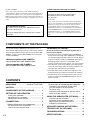
CONTENTS
UNPACKING .................... Inside of Front Cover
CAUTION .........................................................1
COMPONENTS OF THE PACKAGE .............. 2
SETTING UP THE SPEAKERS ...................... 3
Placing the subwoofer ................................... 3
Mounting the rear speakers
............................ 4
Mounting the center speaker .......................... 5
CONNECTIONS.............................................. 6
General information for connections ............ 6
An example of basic connections .................... 6
How to connect speaker cords ........................ 7
Various ways of connecting the subwoofer
.... 8
Connecting the subwoofer to line output
(pin jack) terminals of the amplifier
(The basic way) .................................................
8
Connecting the subwoofer to speaker output
terminals of the amplifier
................................ 9
USING THE SUBWOOFER (YST-SW45) ..... 10
Controls and their functions............................. 10
Automatic power-switching funtion ................... 11
Adjusting the subwoofer before use ................ 12
Frequency characteristics................................. 13
ADVANCED YAMAHA ACTIVE SERVO
TECHNOLOGY (for YST-SW45) .................. 14
TROUBLESHOOTING .................................. 15
SPECIFICATIONS ........................................ 16
COMPONENTS OF THE PACKAGE
The speaker package “NS-P610” is designed for use in a
multi-channel audio system such as a home theater system.
The package includes two pairs of main/rear speakers (NS-
10MMT), a center speaker (NS-C10MM) and a subwoofer
system (YST-SW45).
<Main/rear speakers (NS-10MMT)>
2-way 2-speaker bass-reflex speaker system
<Center speaker (NS-C10MM)>
2-way 3-speaker bass-reflex speaker system
<Subwoofer (YST-SW45)>
Active Servo Processing Subwoofer System with a
built-in power amplifier
● This subwoofer system employs Advanced YAMAHA
Active Servo Technology which YAMAHA has developed
for reproducing higher quality super-bass sound. (Refer to
page 14 for details on Advanced YAMAHA Active Servo
Technology.) This super-bass sound adds a more
realistic, theater-in-the-home effect to your stereo system.
●
This subwoofer can be easily added to your existing audio
system by connecting to either the speaker terminals or the
line output (pin jack) terminals of the amplifier.
● The HIGH CUT control enables you to adjust the tone
balance between the subwoofer and the main speakers.
● The Automatic power-switching function saves you the
trouble of pressing the STANDBY/ON button to turn the
power on and off.
For U.K. customers
If the socket outlets in the home are not suitable for the plug
supplied with this appliance, it should be cut off and an appropriate 3
pin plug fitted. For details, refer to the instructions described below.
Note: The plug severed from the mains lead must be destroyed, as a
plug with bared flexible cord is hazardous if engaged in a live socket
outlet.
SPECIAL INSTRUCTIONS FOR U.K. MODEL
IMPORTANT:
THE WIRES IN MAINS LEAD ARE COLOURED IN
ACCORDANCE WITH THE FOLLOWING CODE:
Blue: NEUTRAL
Brown: LIVE
As the colours of the wires in the mains lead of this apparatus
may not correspond with the coloured markings identifying the
terminals in your plug, proceed as follows: The wire which is
coloured BLUE must be connected to the terminal which is
marked with the letter N or coloured BLACK. The wire which is
coloured BROWN must be connected to the terminal which is
marked with the letter L or coloured RED. Making sure that
neither core is connected to the earth terminal of the three pin
plug.
For Canadian Customers
To prevent electric shock, match wide blade of plug to
wide slot and fully insert.
This Class B digital apparatus complies with Canadian
ICES-003.

English
E-3
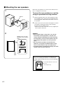
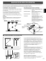
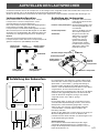
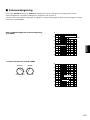
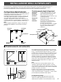
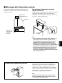
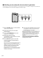
䡵 Placing the subwoofer
It is recommended to place the subwoofer on the outside of
either the right or the left main speaker. (See fig. Å .) The
placement shown in fig. ı is also possible, however, if the
subwoofer system is placed directly facing the wall, the
bass effect may die because the sound from it and the
sound reflected by the wall may cancel out each other. To
prevent this from happening, face the subwoofer system at
an angle as shown in fig. Å.
Note
There may be a case that you cannot obtain enough super-
bass sounds from the subwoofer when listening in the
center of the room. This is because “standing waves” have
been developed between two parallel walls and they cancel
the bass sounds.
In such a case, face the subwoofer obliquely to the wall. It
also may be necessary to break up the parallel surfaces by
placing bookshelves etc. along the walls.
Use the rubber pads
Put the provided rubber pads at the four corners on the
bottom of the subwoofer to prevent the subwoofer moving
due to vibrations etc.
( : Subwoofer, : Main speaker)
ıÅ
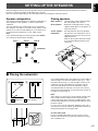
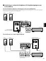
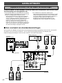
SETTING UP THE SPEAKERS
Before making connections, place all speakers in their respective positions. The positioning of the speakers is important
because it controls the whole sound quality of this system.
Place the speakers depending on your listening position by following the instructions below.
Speaker configuration
This speaker package employs a 6 speaker configuration: 2
main speakers, 2 rear speakers, a center speaker and a
subwoofer.
The main speakers are used for main source sound. The
rear speakers are used for surround sounds, and the center
speaker is for center sounds (dialog etc.). The subwoofer is
for reinforcing low frequencies on your audio system.
Note
In this speaker package, the same speakers (NS-10MMT)
are used for the main and rear speakers.
Placing speakers
Main speakers: On both sides of and at approximately
the same height as the TV set.
Rear speakers: Behind your listening position, facing
slightly inward. About 1.8 m (approx. 6
feet) from the floor.
Center speaker: Precisely between the main speakers.
Subwoofer: The position of the subwoofer is not so
critical because low bass tones are not
highly directional.
Refer to “Placing the subwoofer” below
for a recommended positioning of the
subwoofer.
Main L Center Main R
Rear L
Subwoofer
Rear R
Main R
Center
Subwoofer
Rear R
Rear L
Main L
TV-set

E-4
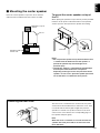
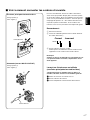
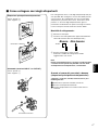
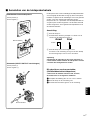
Mount the rear speakers on a shelf, rack or directly on the
floor, or hang them on the wall.
To mount the rear speakers on a wall by
using the provided mounting brackets
1 Attach the bracket to the rear of the speaker by using
the provided screws. Remove the provided pads from
the backing sheet and put them at the lower corners of
the speakers.
2 Fasten screws into a firm wall or wall support as shown
in the figure, and hang the holes of the mounting
bracket on the protruding screws.
* Make sure that the screws are securely caught by the
narrow parts of the holes.
WARNING
● Each speaker weighs 1.5 kg (3 lbs. 5 oz.). Do not
mount them on thin plywood or a wall with soft
surface material. If mounted, the screws may come
out of the flimsy surface and the speakers may fall.
This damages the speakers or causes personal
injury.
● Do not install the speakers to a wall with nails,
adhesives, or any other unstable hardware. Long-
term use and vibrations may cause them to fall.
● To avoid accidents resulting from tripping over loose
speaker cords, fix them to the wall.
䡵 Mounting the rear speakers
1
2
Wall/ wall
support
Tapping screw (4–5 mm)
(Available at the hardware
store)
40 mm
Min.
20 mm
2 mm
60 mm
Pads
Screw
Bracket
You can also use the screw holes on the bottom of the
speaker for installing the speakers on commericially
available speaker stands (if you do not use the provided
mounting brackets.)
A screw with a diameter of 4 mm can
be used.
(Hole depth : 8 mm)

English
E-5
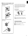
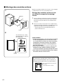
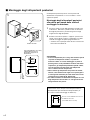
Place the center speaker on top of the TV, on the floor
under the TV or inside the TV rack so that it is stable.
䡵 Mounting the center speaker
The front cover is fastened to the enclosure at four points
and can be removed if desired. To remove the cover, hold
on to both sides and slowly pull straight away from the
speaker. To reattach, line up the four holes on the inner
surface of the cover with the four corresponding pegs on
the speaker and push gently.
Note
When the cover is removed, be sure not to touch the
speaker units with your hands or to exert excessive
force with tools.
1
2
To mount the center speaker on top of
the TV
When placing the speaker on top of the TV, put the provided
fasteners at two points on both the bottom of the speaker
and on top of the TV to prevent the speaker from falling.
Notes
● Do not place the speaker on top of the TV whose area
is smaller than the bottom area of the speaker. If
placed, the speaker may fall and might cause
personal injury.
● Though this speaker is a magnetically shielded type,
there may be some influence on a TV picture
depending on the type of TV or the placement of the
speaker. In such a case, place the speaker apart from
TV so that there is no influence on TV picture.
Fastener
Speaker on top of
the TV
TV set
Speaker inside
the TV rack
Removing the front cover

E-6
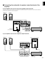
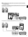
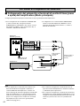
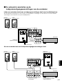
CONNECTIONS
Caution: Plug in the subwoofer and other audio/video components after all connections are
completed.
● Connect the main, center and rear speakers to the
speaker output terminals of your amplifier with the
provided speaker cords.
* Connect each speaker making sure not to reverse the
polarity (+, –). If the speaker is connected with
reversed polarity, the sound will be unnatural and lack
bass.
* For the main and rear speakers only, connect one
speaker to the left (marked L) terminals of your
amplifier, and another speaker to the right (marked R)
terminals.
● The subwoofer can be connected to either the line output
(pin jack) terminals or the speaker output terminals of the
amplifier. Choose one of the ways shown in this section
that is more suitable for your audio system. Also, refer to
the owner’s manual of your component to be connected
to the subwoofer.
䡵 An example of basic connections
Basically, connect the subwoofer to the line output (pin jack) terminal(s) of the amplifier. (Refer to page 8 for details.) If your
amplifier does not have any line output terminal, connect the subwoofer to the speaker output terminals of the amplifier. (Refer
to page 9 for details.)
LeftRight
Subwoofer (General model)
Amplifier
To AC outlet
Center speaker
Rear speakers
Left
Right
Main speakers
General information for connections
SPEAKERS
MAIN CENTER REAR
(SURROUND)
OUTPUT
SUB
WOOFER
CAUTION
SEE INSTRUCTION
MANUAL FOR CORRECT SETTING.
MAIN
A
B
A
B
CENTER REAR
(SURROUND)
OUTPUT INPUT2
TO SPEAKERS
INPUT1
FROM AMPLIFIER
LOW
HIGH
OFF
AUTO
STANDBY
240V
VOLTAGE
SELECTOR
POWER
ON
OFF
OUTPUT INPUT2
TO SPEAKERS
INPUT1
FROM AMPLIFIER
LOW
HIGH
OFF
AUTO
STANDBY
REAR L
REAR L
FRONT R
FRONT R
FRONT L
FRONT L
CENTER
REAR R
CENTER
REAR R

English
E-7
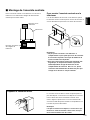
For connections, keep the speaker cords as short as
possible. Do not bundle or roll up the excess part of the
cords. If the connections are faulty, no sound will be heard
from the speakers. Make sure that the + and – polarity
markings of the speaker cords are observed and set
correctly. If these cords are reversed, the sound will be
unnatural and lack bass.
How to Connect:
1 Loosen the knob.
2 Insert the bare wire. [Remove approx. 10 mm (3/8”)
insulation from the speaker cords.]
3 Tighten the knob and secure the cord.
Test the firmness of the connection by pulling lightly on
the cord at the terminal.
Note
Do not let the bare speaker wires touch each other as
this could damage the speaker or the amplifier, or both
of them.
When using a banana plug
(main/center/rear speakers)
<U.S.A., Canada, Australia, China and General models
only>
1 Remove the cover by pulling it toward you.
2 Tighten the terminal knob.
3 Simply insert the banana plug into the terminal.
10 mm
1
2
3
Subwoofer (INPUT1/OUTPUT terminals)
Red: positive (+)
Black: negative (–)
Main/center/rear speakers
Red: positive (+)
Black: negative (–)
1
2
2
3
䡵 How to connect speaker cords
2
3
1
Banana plug
Banana plug
1

E-8
Notes
● Some amplifiers have line output terminals labeled PRE
OUT. When you connect the subwoofer to the PRE OUT
terminals of the amplifier, make sure that the amplifier
has at least two sets of PRE OUT terminals. If the
amplifier has only one set of PRE OUT terminals, do not
connect the subwoofer to the PRE OUT terminals.
Instead, connect the subwoofer to the speaker output
terminals of the amplifier. (Refer to pages 6 and 7.)
● When connecting to a monaural line output terminal of
the amplifier, connect the L INPUT2 terminal.
● When connecting to line output terminals of the amplifier,
other speakers should not be connected to the OUTPUT
terminals on the rear panel of the subwoofer. If
connected, they will not produce sound.
Subwoofer (General model)
Amplifier
Pin plug cord
(included)
To AC outlet
Various ways of connecting the subwoofer
● To connect with a YAMAHA DSP amplifier (or AV
receiver), connect the SUBWOOFER (or LOW PASS etc.)
terminal on the rear of the DSP amplifier (or AV receiver)
to the L INPUT2 terminal of the subwoofer.
䡵 Connecting the subwoofer to line output (pin jack) terminals of
the amplifier (The basic way)
Connect the main speakers to the speaker output terminals of the amplifier.
● To connect the subwoofer to the SPLIT SUBWOOFER
terminals on the rear of the DSP amplifier, connect them
to both the left L and right R INPUT2 terminals of the
subwoofer.
Pin plug cords
(not included)
OUTPUT INPUT2
TO SPEAKERS
INPUT1
FROM AMPLIFIER
LOW
HIGH
OFF
AUTO
STANDBY
240V
VOLTAGE
SELECTOR
POWER
ON
OFF
OUTPUT INPUT2
TO SPEAKERS
INPUT1
FROM AMPLIFIER
LOW
HIGH
OFF
AUTO
STANDBY
SPLIT SUBWOOFER
SUBWOOFER
(LOW PASS)

English
E-9
䡵 Connecting the subwoofer to speaker output terminals of the
amplifier
If your amplifier has only one set of main speaker output terminals
Connect the speaker output terminals of the amplifier to the INPUT1 terminals of the subwoofer, and connect the OUTPUT
terminals of the subwoofer to the main speakers.
Right main
speaker
Left main
speaker
Subwoofer
(General model)
Amplifier
Speaker
output
terminals
To AC outlet
If your amplifier has two sets of speaker output terminals
(Both A and B speaker outputs
must be ON.)
Subwoofer (General model)
Amplifier
Speaker output terminals
To AC outlet
Right main
speaker
Left main
speaker
OUTPUT INPUT2
TO SPEAKERS
INPUT1
FROM AMPLIFIER
LOW
HIGH
OFF
AUTO
STANDBY
240V
VOLTAGE
SELECTOR
POWER
ON
OFF
OUTPUT INPUT2
TO SPEAKERS
INPUT1
FROM AMPLIFIER
LOW
HIGH
OFF
AUTO
STANDBY
OUTPUT INPUT2
TO SPEAKERS
INPUT1
FROM AMPLIFIER
LOW
HIGH
OFF
AUTO
STANDBY
240V
VOLTAGE
SELECTOR
POWER
ON
OFF
AB
OUTPUT INPUT2
TO SPEAKERS
INPUT1
FROM AMPLIFIER
LOW
HIGH
OFF
AUTO
STANDBY

E-10
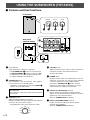
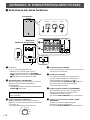
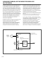
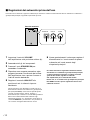
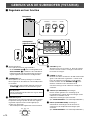
USING THE SUBWOOFER (YST-SW45)
1 Power indicator
Lights up while the subwoofer is turned on.
* If the STANDBY/ON (2) button is pressed in and
the AUTO STANDBY (9) switch is set to the HIGH
or LOW position, this indicator lights up dimly when
no signal is inputted to the subwoofer.
2 STANDBY/ON button
Press this button to turn on the power. Press again to
set the subwoofer in the standby mode.
* This button can be used only when the POWER (5)
switch is set in the ON position.
Standby mode
The subwoofer is still using a small amount of power
in this mode.
3 HIGH CUT control
Adjusts the high frequency cut off point.
Frequencies higher than the frequency selected by this
control are all cut off (and no output).
* One graduation of this control represents 10 Hz.
4 VOLUME control
Adjusts the volume level. Turn the control clockwise to
increase the volume, and counterclockwise to
decrease the volume.
5 POWER switch
Normally, set this switch to the ON position to use the
subwoofer. In this state, you can turn on the subwoofer
or turn the subwoofer into the standby mode by
pressing the STANDBY/ON (2) button. Set this
switch to the OFF position to completely cut off the
subwoofer’s power supply from the AC line.
6 OUTPUT (TO SPEAKERS) terminals
Can be used for connecting to the main speakers.
Signals are sent directly from the amplifier to the main
speakers by way of these terminals.
(Refer to “CONNECTIONS” for details.)
7 INPUT1 (FROM AMPLIFIER) terminals
Used to connect the subwoofer with the speaker
terminals of the amplifier.
(Refer to “CONNECTIONS” for details.)
Rear panel
(General model)
䡵 Controls and their functions
SUPERWOOFER SYSTEM YST-SW45
HIGH CUTSTANDBY/ON
150Hz50Hz
VOLUME
100
150 Hz
010
50 Hz
STANDBY/ON HIGH CUT VOLUME
1
23
4
OUTPUT INPUT2
TO SPEAKERS
INPUT1
FROM AMPLIFIER
LOW
HIGH
OFF
AUTO
STANDBY
240V
VOLTAGE
SELECTOR
POWER
ON
OFF
5
OUTPUT INPUT2
TO SPEAKERS
INPUT1
FROM AMPLIFIER
LOW
HIGH
OFF
AUTO
STANDBY
8
9
6
7
240V
VOLTAGE
SELECTOR
0
POWER
ON
OFF
Front panel
150 Hz50 Hz
60 Hz
70 Hz
80 Hz
90 Hz
100 Hz
110 Hz
120 Hz
130 Hz
140 Hz

English
E-11
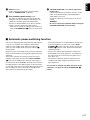
If the source being played is stopped and the input signal is
cut off for 7 to 8 minutes, the subwoofer automatically
switches to the standby mode. (When the subwoofer
switches to the standby mode, the power indicator (1)
becomes dim.)
When you play a source again, the power of the subwoofer
turns on automatically by sensing audio signals input to the
subwoofer.
This function operates by sensing a certain level of low
frequency input signal. Usually set the AUTO STANDBY
(9) switch to the LOW position. However, if the power is
not switched to ON or STANDBY smoothly, set the switch to
the HIGH position. In the HIGH position, the power will turn
on even with a low level of input signal. But please be aware
that the subwoofer may not switch to the standby mode
when there is an extremely low input signal.
* The power might turn on unexpectedly by sensing noise
from other appliances. If that occurs, set the AUTO
STANDBY (9) switch to the OFF position and use the
POWER (5) switch to switch the power between ON
and OFF manually.
* This function detects the low-frequency components
below 200 Hz of the input signals (i.e., the explosion in
the action movie, the sound of the bass guitar or the
bass drum, etc.).
* The minutes required to switch the subwoofer to the
standby mode might change by sensing noise from
other appliances.
This function is available only when the power of the
subwoofer is on (by pressing the STANDBY/ON (2)
button).
8 INPUT2 terminals
Used to input line level signals from the amplifier.
(Refer to “CONNECTIONS” for details.)
9 AUTO STANDBY (HIGH/LOW/OFF) switch
This switch is originally set to the OFF position. By
setting this switch to the HIGH or LOW position, the
subwoofer’s automatic power-switching function
operates as described below. If you do not need this
function, leave this switch in the OFF position.
* Make sure to change the setting of this switch only
when the STANDBY/ON (2) button is not pressed
in.
0 VOLTAGE SELECTOR switch (China and general
models only)
If the preset setting of the switch is incorrect, set the
switch to the proper voltage range (220V-240V or
110V-120V) of your area.
Consult your dealer if you are unsure of the correct
setting.
WARNING
Be sure to unplug the subwoofer before setting the
VOLTAGE SELECTOR switch correctly.
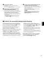
䡵 Automatic power-switching function

E-12
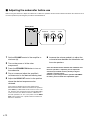
1 Set the VOLUME control of the amplifier to
minimum (0).
2 Turn on the power of all the other
components.
3 Press the STANDBY/ON button to turn on
the subwoofer.
4 Play a source and adjust the amplifier’s
volume control to the desired listening level.
5 Adjust the HIGH CUT control to the position
where the desired response can be
obtained.
This system is designed so that the optimum tone
balance between the subwoofer and the main speakers
(NS-10MMT) is obtained when this control is set at 110
Hz. However, the tone balance may change depending
on the room size, the distance from the subwoofer to
the main speakers, etc. So, if you prefer, turn the HIGH
CUT control and set it to a position where a better tone
balance is obtained.
䡵 Adjusting the subwoofer before use
Before using the subwoofer, adjust the subwoofer to obtain the optimum volume and tone balance between the subwoofer and
the main speakers by following the procedures described below.
6 Increase the volume gradually to adjust the
volume balance between the subwoofer and
the main speakers.
Once the volume balance between the subwoofer and
the main speakers is adjusted, you can adjust the
volume of your whole sound system by using the
amplifier’s volume control.
However, if you change the main speakers NS-10MMT
to others, you must make this adjustment again.
SUPERWOOFER SYSTEM YST-SW45
HIGH CUTSTANDBY/ON
150Hz50Hz
VOLUME
100
150 Hz
010
50 Hz
STANDBY/ON HIGH CUT VOLUME
Front panel
653

English
E-13
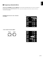
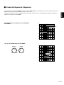
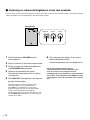
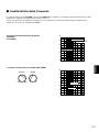
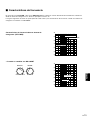
䡵 Frequency characteristics
Adjustment of the VOLUME control and the HIGH CUT control should be changed depending on the room size, the distance
from the subwoofer to the main speakers, sources, etc.
Following figures show the optimum adjustment of each control and the frequency characteristics when this subwoofer is
combined with NS-10MMT.
Frequency characteristics of this subwoofer
(YST-SW45)
●
When combined with NS-10MMT
20 50 100 200 500Hz
40
50
60
70
80
90
dB
HIGH CUT 100 Hz
HIGH CUT 150 Hz
HIGH CUT 50 Hz
20 50 100 200 500Hz
40
50
60
70
80
90
dB
YST-SW45
NS-10MMT
HIGH CUT VOLUME
150 Hz
010
50 Hz

E-14
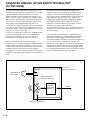
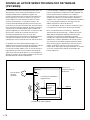
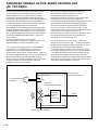
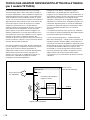
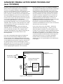
ADVANCED YAMAHA ACTIVE SERVO TECHNOLOGY
(for YST-SW45)
The theory of Yamaha Active Servo Technology has been
based upon two major factors, the Helmholtz resonator and
negative-impedance drive. Active Servo Processing
speakers reproduce the bass frequencies through an “air
woofer”, which is a port or opening in the speaker’s cabinet.
This opening is used instead of, and performs the functions
of, a woofer in a conventionally designed speaker system.
Thus, signals of low amplitude within the cabinet can,
according to the Helmholtz resonance theory, be outputted
from this opening as waves of great amplitude if the size of
the opening and the volume of the cabinet are in the correct
proportion to satisfy a certain ratio.
In order to accomplish this, moreover, the amplitudes within
the cabinet must be both precise and of sufficient power
because these amplitudes must overcome the “load”
presented by the air that exists within the cabinet.
Thus it is this problem that is resolved through the
employment of a new design in which the amplifier supplies
special signals. If the electrical resistance of the voice coil
could be reduced to zero, the movement of the speaker unit
would become linear with respect to signal voltage. To
accomplish this, a special negative-impedance output-drive
amplifier for subtracting output impedance of the amplifier is
used.
By employing negative-impedance drive circuits, the
amplifier is able to generate precise, low-amplitude, low-
frequency waves with superior damping characteristics.
These waves are then radiated from the cabinet opening as
high-amplitude signals. The system can, therefore, by
employing the negative-impedance output drive amplifier
and a speaker cabinet with the Helmholtz resonator,
reproduce an extremely wide range of frequencies with
amazing sound quality and less distortion.
The features described above, then, are combined to be the
fundamental structure of the conventional Yamaha Active
Servo Technology.
Our new Active Servo Technology — Advanced Yamaha
Active Servo Technology — adopted Advanced Negative
Impedance Converter (ANIC) circuits, which allows the
conventional negative impedance converter to dynamically
vary in order to select an optimum value for speaker
impedance variation. With this new ANIC circuits, Advanced
Yamaha Active Servo Technology can provide more stable
performance and improved sound pressure compared with
the conventional Yamaha Active Servo Technology, resulting
in more natural and dynamic bass reproduction.
High-amplitude
bass sound
Cabinet
Port
Air woofer
(Helmholtz resonator)
Active Servo
Processing
Amplifier
Signals
Signals of low amplitude
Advanced Negative-
impedance Converter

English
E-15
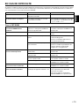
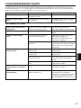
Problem
No sound.
Sound level is too low.
What to Do
Connect them securely.
Connect them correctly, that is L (left) to
L, R (right) to R, “+” to “+” and “–” to “–”.
Cause
Speaker cords are not connected
securely.
Speaker cords are not connected
correctly.
TROUBLESHOOTING
Refer to the chart below when this unit does not function properly. If the problem you are experiencing is not listed below or if
the instructions given below do not help, disconnect the power cord and contact your authorized YAMAHA dealer or service
center.
For YST-SW45
Power is not supplied even
though the STANDBY/ON button
is pressed in.
No sound.
Sound level is too low.
The subwoofer will not turn on
automatically.
The subwoofer turns into the
standby mode unexpectedly.
The subwoofer turns on
unexpectedly.
The power cord is not plugged in, or the
POWER switch is set to the OFF
position.
The VOLUME control is set to 0.
A source sound with few bass
frequencies is played.
It is influenced by standing waves.
The POWER switch is set to the OFF
position.
The STANDBY/ON button is set to OFF.
The AUTO STANDBY switch is set to
the OFF position.
The level of input signal is too low.
The level of input signal is too low.
There is an influence of noise
generated from external appliances etc.
Plug the power cord into an AC outlet
and/or set the POWER switch to the ON
position.
Turn the VOLUME control to the right.
Play a source sound with bass
frequencies.
Set the HIGH CUT control to a higher
position.
Reposition the subwoofer or break up
the parallel surface by placing
bookshelves etc. along the walls.
Set the POWER switch to the ON
position.
Set the STANDBY/ON button to ON.
Set the AUTO STANDBY switch to the
“HIGH” or “LOW” position.
Set the AUTO STANDBY switch to the
“HIGH” position.
Set the AUTO STANDBY switch to the
“HIGH” position.
Move the subwoofer farther away from
such appliances and/or reposition the
connected speaker cables.
Otherwise, set the AUTO STANDBY
switch to the “OFF” position.

E-16
SPECIFICATIONS
NS-10MMT
Type ............. 2-way 2-speaker bass-reflex speaker system
Magnetically shielded type
Driver
Woofer ...................................... 9 cm (3-9/16”) cone type
Tweeter .......................... 2.5 cm (1”) balanced dome type
Nominal Input Power ................................................. 40W
Maximum Input Power ............................................. 100W
Impedance ..................................................................... 6Ω
Frequency Response ................................ 75 Hz – 33 kHz
Sensitivity ................................................... 88 dB/2.83V/m
Crossover Frequency .............................................. 7 kHz
Dimensions (W x H x D) ...... 107 mm x 191 mm x 141 mm
(4-3/16” x 7-1/2” x 5-9/16”)
Weight ............................................ 1.5 kg (3 lbs. 5 oz.) x 4
NS-C10MM
Type ............. 2-way 3-speaker bass-reflex speaker system
Magnetically shielded type
Driver
Woofer ................................ 9 cm (3-9/16”) cone type x 2
Tweeter .......................... 2.5 cm (1”) balanced dome type
Nominal Input Power ................................................. 50W
Maximum Input Power ............................................. 125W
Impedance ..................................................................... 6Ω
Frequency Response .............................. 100 Hz – 33 kHz
Sensitivity ................................................... 91 dB/2.83V/m
Crossover Frequency .............................................. 7 kHz
Dimensions (W x H x D) ...... 312 mm x 101 mm x 141 mm
(12-5/16” x 4” x 5-9/16”)
Weight .................................................. 2.3 kg (5 lbs. 1 oz.)
YST-SW45
Type ............... Active Servo Processing Subwoofer System
Driver ............................... 20 cm (8”) cone woofer (JA2162)
Magnetically shielded type
Amplifier Output .................................................... 70W/5Ω
High-Cut Filter ...................... 50 Hz – 150 Hz (–24 dB/oct.)
Frequency Response ................. 30 Hz – 200 Hz (–10 dB)
Power Supply
U.S.A. and Canada models .................... AC 120V, 60 Hz
U.K. and Europe models ........................ AC 230V, 50 Hz
Australia model....................................... AC 240V, 50 Hz
China and General models
....................................... AC 110-120/220-240V, 50/60 Hz
Power Consumption ................................................... 55W
Dimensions (W x H x D) ...... 235 mm x 365 mm x 318 mm
(9-5/16” x 14-7/20” x 12-1/2”)
Weight .................................................. 9 kg (19 lbs. 13 oz.)
Accessories
Pin plug cord [3 m (9.8 feet)] x 1
Speaker cord [10 m (32.8 feet)] x 4
Speaker cord [4 m (13.1 feet)] x 3
Mounting bracket x 4
Screw x 8
Pad (for NS-10MMT) x 8
Fastener x 4
Rubber pad (for YST-SW45) x 4
* Please note that all specifications are subject to change
without notice.

Français
F-1
●
Pour garantir les meilleures performances possibles, lire ce manuel avec
attention. Le garder dans un endroit sûr pour une utilisation ultérieure.
●
Installer ces enceintes dans un endroit frais, sec et propre, loin
de fenêtres, sources de chaleur et d’endroits où les vibrations, la
poussière, l’humidité ou le froid sont importants. Eviter les
sources de bourdonnements (transformateurs, moteurs). Pour
éviter les incendies ou électrocution, ne pas exposer ces
enceintes à la pluie ni à l’humidité.
●
Pour éviter que le coffret se gondole ou se décolore, ne pas
placer les enceintes à un endroit ou elles seront exposées aux
rayons directs du soleil ou à une trop forte humidité.
●
Ne pas placer les objets suivants sur les enceintes :
●
D’autres composants, car ils pourraient endommager et/ou
décolorer la surface des enceintes.
●
Des objets inflammables (ex. des bougies), car elles
pourraient provoquer un incendie, endommager les enceintes
et/ou provoquer des blessures corporelles.
●
Des récipients contenant des liquides, car ils pourraient provoquer
une décharge électrique et/ou endommager les enceintes.
●
Ne pas placer les enceintes à un endroit où elles risquent d’être
renversées ou percutées par des objets tombants. Un endroit
bien stable améliorera aussi la qualité du son.
●
Si les enceintes sont placées sur la même étagère ou dans le
même meuble que le tourne-disque, un effet de retour sonore
risquera de se produire.
●
Le propriétaire du système est entièrement responsable du bon
positionnement et de la bonne installation du système.
YAMAHA décline toute responsabilité en cas d’accident causé par
un positionnement ou une installation inadéquat des enceintes.
●
Si des distorsions sonores se produisent, réduire le niveau sonore
en baissant la commande de volume de l’amplificateur. Ne jamais
laisser de “pincement” sonore se produire sur l’amplificateur.
Sinon, les enceintes risqueront d’être endommagées.
●
Lorsqu’on utilise un amplificateur dont la puissance de sortie nomi-
nale est supérieure à la puissance d’entrée nominale des enceintes,
il faut veiller à ne pas dépasser l’entrée maximale des enceintes.
●
Ne pas essayer de nettoyer ces enceintes avec des diluants chimi-
ques, ceci endommagerait le fini. Utiliser un chiffon propre et sec.
●
Ne pas essayer de modifier ou fixer les enceintes. Contacter un
dépanneur YAMAHA qualifié en cas de nécessité de réparation. Le
coffret ne doit jamais être ouvert pour quelque raison que ce soit.
●
Bien lire la section “EN CAS DE DIFFICULTE” concernant les
erreurs de fonctionnement communes avant de conclure que les
enceintes sont défectueuses.
Pour le YST-SW45 uniquement
●
Ne pas utiliser cet appareil à l’envers. Il risque d’être en
surchauffe et de provoquer des dommages.
●
Ne pas forcer les commutateurs, les touches ou les câbles de
raccordement. Lors du déplacement de l’appareil, d’abord
débrancher la prise d’alimentation et les câbles le raccordant à
d’autres appareils. Ne jamais tirer sur les cordons.
●
Cet appareil possédant un amplificateur intégré, de la chaleur
sera irradiée par le panneau arrière. Placer l’appareil à une
certaine distance des murs, en laissant un espace de 20 cm au-
dessus, derrière et des deux côtés de l’appareil afin d’éviter tout
risque de dommage ou d’incendie. Ne pas positionner non plus
cet appareil dos au plancher ou à une autre surface.
●
Pour éviter une condensation à l’intérieur de cet appareil, ne pas
exposer cet appareil à des variations brusques de température
en le transportant d’un endroit froid vers un endroit chaud et ne
pas placer cet appareil dans un envrionnement où le degré
d’humidité est élevé ( ex. dans une pièce avec humidificateur).
La condensation risque de provoquer une décharge électrique,
un incendie, et/ou d’endommager cet appareil.
PRECAUTIONS D’USAGE: Tenir compte des précautions
ci-dessous avant de faire fonctionner l’appareil.
Nous vous remercions d’avoir porté votre choix sur cet ensemble d’enceintes NS-P610 de YAMAHA.
●
Ne pas couvrir le panneau arrière de cet appareil avec quoi que
ce soit, journal, nappe, rideau, etc. afin de ne pas entraver la
dissipation de la chaleur. Si la température à l’intérieur de cet
appareil augmente, un incendie peut se déclarer et endommager
cet appareil et/ou causer une blessure corporelle.
●
Ne pas brancher cet appareil à une prise murale avant d’avoir
terminé toutes les connexions.
●
Le voltage à utiliser doit être le même que celui celle spécifiée sur le
panneau arrière. Utiliser cet appareil avec une plus haute tension
que spécifié est dangereux et peut causer un incendie, endommager
cet appareil et/ou causer une blessure corporelle. YAMAHA ne se
tiendra pas responsable d’aucun dommage résultant de l’uitlisation
de cet appareil avec une tension autre que spécifiée.
●
Pour prévenir tout dégât dû à la foudre, débrancher la prise
d’alimentation CA en cas d’orage.
●
Les sons de très basse fréquence produits par cet appareil
peuvent provoquer un sifflement sur le tourne-disque. Dans ce
cas, éloigner cet appareil du tourne-disque.
●
Cette unité peut être endommagée si certains sons sont ér
niveau sonore. Par exemple, si des ondes sinusoïdales de 20 –50
Hz d’un disque d’essai, des sons de graves d’instruments
électroniques, etc. son émis en continu ou si la pointe de lecture
d’une platine tourne-disque touche la surface d’un disque, réduire le
niveau de volume pour éviter d’endommager cet appareil.
●
Si une distorsion se fait entendre (par exemple des petits coups
secs intermittents ou un “martèlement”) sur cet appareil, diminuer
le niveau sonore. La lecture à très haut volume des sons de
basse ou des sons de basses fréquences de la bande sonore
d’un film, ou de passages de musique populaire de forte intensité,
sont susceptibles d’endommager ce système d’enceintes.
●
Des vibrations générées par des fréquences supergraves
risquent de déformer les images sur un téléviseur. Dans ce cas,
éloigner cet appareil du téléviseur.
●
Lors du débranchement du cordon d’alimentation de la prise
murale, saissir la fiche ; ne pas tirer le cordon.
●
Lorsqu’on prévoit de ne pas utiliser cet appareil pendant
longtemps (pendant les vacances, par exemple), débrancher le
cordon d’alimentation CA de la prise murale.
Mode veille (Standby)
Lorsque cet appareil est éteint en appuyant sur la touche
STANDBY du panneau avant, il consomme peu de courant. Cet
état s’appelle le mode veille. L’alimentation de l’appareil est
coupée complètement de la ligne AC uniquement quand
l’interrupteur POWER du panneau arrière est placé en position
OFF ou si le cordon d’alimentation secteur est débranché.
Ces enceintes incorporent un blindage de limitation du
rayonnement magnétique, mais il risque quand même d’affecter
la qualité d’image couleur d’un téléviseur placé trop près. Dans
ce cas, éloigner les enceintes du téléviseur.

F-2
TABLE DES MATIERES
DEBALLAGE ........ Intérieur du couvercle avant
PRECAUTIONS D’USAGE..............................1
ELEMENTS DE L’ENSEMBLE....................... 2
DISPOSITION DES ENCEINTES ................... 3
Positionnement du subwoofer ........................ 3
Montage des enceintes arrière
....................... 4
Montage de l’enceinte centrale ....................... 5
CONNEXIONS ................................................ 6
Informations générales concernant les
raccordements ............................................. 6
Exemple de raccordement de base ................. 6
Voici comment connecter les cordons
d’enceinte .................................................... 7
Différentes manières de raccorder le
subwoofer
..................................................... 8
Raccordement du subwoofer aux bornes de
sortie de ligne
(fiche jack) de l’amplificateur
(méthode de base)
......................................... 8
Raccordement du subwoofer aux bornes de
sortie d’enceintes de l’amplificateur
.................. 9
UTILISATION DU SUBWOOFER (YST-SW45)
.......................................................................10
Les commandes et leurs fonctions ................. 10
Fonction de commutation d’alimentation
automatique ................................................ 11
Réglage du subwoofer avant l’utilisation
......... 12
Caractéristiques de fréquence ....................... 13
ATIVE SERVO TECHNOLOGIE AVANCEE
YAMAHA (YST-SW45).................................. 14
EN CAS DE DIFFICULTE ............................. 15
CARACTERISTIQUES TECHNIQUES......... 16
ELEMENTS DE L’ENSEMBLE
L’ensemble d’enceintes “NS-P610” est conçu pour être
utilisé avec un système audio multi-canaux, telle qu’une
installation Home Cinéma.
L’ensemble comprend deux paires d’enceintes principales/
arrière (NS-10MMT), une enceinte centrale (NS-C10MM),
et un subwoofer (YST-SW45).
<Enceintes principales/arrières (NS-10MMT)>
Système d’enceinte bass-reflex 2 enceintes 2 voies
<Enceinte centrale (NS-C10MM)>
Système d’enceinte bass-reflex 3 enceintes 2 voies
<Subwoofer (YST-SW45)>
Subwoofer à Active Servo Processing avec
amplificateur incorporé
● Ce subwoofer utilise Advanced YAMAHA Active Servo
Technology mise au point par YAMAHA pour la
reproduction de basses fréquences de meilleure qualité.
(Pour ce qui concerne Advanced YAMAHA Active Servo
Technology, se reporter à la page 14.) Ces basses
fréquences ajoutent un effet réaliste cinématographique
aux sons fournis par une chaîne stéréo.
●
Ce subwoofer peut être facilement ajouté à votre chaîne
actuelle en le raccordant soit aux bornes d’enceintes soit
aux bornes de sortie de ligne (fiche Cinch) de l’amplificateur.
● Le contrôle HIGH CUT permet d’ajuster la balance entre
le subwoofer et les enceintes principales.
● La fonction de commutation d’alimentation automatique
évite d’appuyer sur la touche STANDBY/ON pour allumer
et éteindre l’appareil.
POUR LES CONSOMMATEURS CANADIENS
Pour eviter les chocs electriques, introduire la lame la
plus large de la fiche dans la borne correspondante de
la prise et pousser jusqu’au fond.
Cet appareil numérique de la classe B est conforme à la
norme NMB-003 du Canada.
Sélecteur de tension (VOLTAGE SELECTOR)
(Pour les modèles général et les modèles pour la Chine
uniquement)
Le sélecteur de tension sur le panneau arrière de cet appareil
doit être réglé sur votre tension locale AVANT de brancher
l’appareil sur une prise de courant CA. Les tensions sont de
110-120/220-240V CA 50/60 Hz.
La pagina sta caricando ...
La pagina sta caricando ...
La pagina sta caricando ...
La pagina sta caricando ...
La pagina sta caricando ...
La pagina sta caricando ...
La pagina sta caricando ...
La pagina sta caricando ...
La pagina sta caricando ...
La pagina sta caricando ...
La pagina sta caricando ...
La pagina sta caricando ...
La pagina sta caricando ...
La pagina sta caricando ...
La pagina sta caricando ...
La pagina sta caricando ...
La pagina sta caricando ...
La pagina sta caricando ...
La pagina sta caricando ...
La pagina sta caricando ...
La pagina sta caricando ...
La pagina sta caricando ...
La pagina sta caricando ...
La pagina sta caricando ...
La pagina sta caricando ...
La pagina sta caricando ...
La pagina sta caricando ...
La pagina sta caricando ...
La pagina sta caricando ...
La pagina sta caricando ...
La pagina sta caricando ...
La pagina sta caricando ...
La pagina sta caricando ...
La pagina sta caricando ...
La pagina sta caricando ...
La pagina sta caricando ...
La pagina sta caricando ...
La pagina sta caricando ...
La pagina sta caricando ...
La pagina sta caricando ...
La pagina sta caricando ...
La pagina sta caricando ...
La pagina sta caricando ...
La pagina sta caricando ...
La pagina sta caricando ...
La pagina sta caricando ...
La pagina sta caricando ...
La pagina sta caricando ...
La pagina sta caricando ...
La pagina sta caricando ...
La pagina sta caricando ...
La pagina sta caricando ...
La pagina sta caricando ...
La pagina sta caricando ...
La pagina sta caricando ...
La pagina sta caricando ...
La pagina sta caricando ...
La pagina sta caricando ...
La pagina sta caricando ...
La pagina sta caricando ...
La pagina sta caricando ...
La pagina sta caricando ...
La pagina sta caricando ...
La pagina sta caricando ...
La pagina sta caricando ...
La pagina sta caricando ...
La pagina sta caricando ...
La pagina sta caricando ...
La pagina sta caricando ...
La pagina sta caricando ...
La pagina sta caricando ...
La pagina sta caricando ...
La pagina sta caricando ...
La pagina sta caricando ...
La pagina sta caricando ...
La pagina sta caricando ...
La pagina sta caricando ...
La pagina sta caricando ...
La pagina sta caricando ...
La pagina sta caricando ...
La pagina sta caricando ...
La pagina sta caricando ...
La pagina sta caricando ...
La pagina sta caricando ...
La pagina sta caricando ...
La pagina sta caricando ...
La pagina sta caricando ...
La pagina sta caricando ...
La pagina sta caricando ...
La pagina sta caricando ...
La pagina sta caricando ...
La pagina sta caricando ...
La pagina sta caricando ...
La pagina sta caricando ...
La pagina sta caricando ...
-
 1
1
-
 2
2
-
 3
3
-
 4
4
-
 5
5
-
 6
6
-
 7
7
-
 8
8
-
 9
9
-
 10
10
-
 11
11
-
 12
12
-
 13
13
-
 14
14
-
 15
15
-
 16
16
-
 17
17
-
 18
18
-
 19
19
-
 20
20
-
 21
21
-
 22
22
-
 23
23
-
 24
24
-
 25
25
-
 26
26
-
 27
27
-
 28
28
-
 29
29
-
 30
30
-
 31
31
-
 32
32
-
 33
33
-
 34
34
-
 35
35
-
 36
36
-
 37
37
-
 38
38
-
 39
39
-
 40
40
-
 41
41
-
 42
42
-
 43
43
-
 44
44
-
 45
45
-
 46
46
-
 47
47
-
 48
48
-
 49
49
-
 50
50
-
 51
51
-
 52
52
-
 53
53
-
 54
54
-
 55
55
-
 56
56
-
 57
57
-
 58
58
-
 59
59
-
 60
60
-
 61
61
-
 62
62
-
 63
63
-
 64
64
-
 65
65
-
 66
66
-
 67
67
-
 68
68
-
 69
69
-
 70
70
-
 71
71
-
 72
72
-
 73
73
-
 74
74
-
 75
75
-
 76
76
-
 77
77
-
 78
78
-
 79
79
-
 80
80
-
 81
81
-
 82
82
-
 83
83
-
 84
84
-
 85
85
-
 86
86
-
 87
87
-
 88
88
-
 89
89
-
 90
90
-
 91
91
-
 92
92
-
 93
93
-
 94
94
-
 95
95
-
 96
96
-
 97
97
-
 98
98
-
 99
99
-
 100
100
-
 101
101
-
 102
102
-
 103
103
-
 104
104
-
 105
105
-
 106
106
-
 107
107
-
 108
108
-
 109
109
-
 110
110
-
 111
111
-
 112
112
-
 113
113
-
 114
114
-
 115
115


Yamaha NS-P610 Manuale del proprietario
- Categoria
- Subwoofer
- Tipo
- Manuale del proprietario
in altre lingue
- English: Yamaha NS-P610 Owner's manual
- français: Yamaha NS-P610 Le manuel du propriétaire
- español: Yamaha NS-P610 El manual del propietario
- Deutsch: Yamaha NS-P610 Bedienungsanleitung
- Nederlands: Yamaha NS-P610 de handleiding
- dansk: Yamaha NS-P610 Brugervejledning
- svenska: Yamaha NS-P610 Bruksanvisning
- Türkçe: Yamaha NS-P610 El kitabı
- română: Yamaha NS-P610 Manualul proprietarului
Documenti correlati
-
Yamaha NS-P610 Manuale utente
-
Yamaha YST-SW45 Manuale del proprietario
-
-
Yamaha SW030 Manuale del proprietario
-
-
-
-
-
Yamaha NS-P210 Manuale del proprietario
-