ATEN Altusen KN2124VA Guida Rapida
- Categoria
- Switch di rete
- Tipo
- Guida Rapida

Kabel sicher verlegen
Zur verbesserten Sicherheit, sichern Sie das Netzkabel mit den Lok-U-Plug-
Kabelhaltern von ATEN. Fixieren Sie die Kabelhalter mithilfe der speziell
angefertigten Löcher, die um die einzelnen Steckdosen herum angebracht
sind. (Weitere Informationen entnehmen Sie dem Benutzerhandbuch zum
KN2124VA / KN2140VA / KN4124VA / KN4140VA.)
Instalar los cables de forma segura
Para más seguridad, fi je el cable de alimentación con los sujetadores para
cables Lok-U-Plug de ATEN. Fije los sujetadores de cables en los agujeros
especialmente distribuidos alrededor de las tomas eléctricas. (Para más detalles,
consulte el manual del usuario del KN2124VA / KN2140VA / KN4124VA /
KN4140VA.)
Connessione sicura dei cavi
Utilizzare i fermacavi ATEN con chiusura di sicurezza Lok-U-Plug per bloccare
in sicurezza il cavo di alimentazione. Fissare i fermacavi tramite i fori
appositamente progettati attorno alle singole prese di alimentazione. (Per
maggiori dettagli, consultare il manuale dell’utente del KN2124VA / KN2140VA
/ KN4124VA / KN4140VA.)
7
3
1
1
5
4
6
2
5
62
7
3
1 4
23 24 25
4
1
2 3
5
6 7 8
23 24 25
4
1
2 3
5
6 7 8
5
62
7
3
1 4
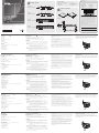
Hardware Review
A
Front View
1. Power LEDs
2. Port LEDs
3. LAN LEDs
4. Laptop USB Console (LUC) Port
5. USB Ports
6. Reset Switch
7. Audio Ports
8. Port Switching Buttons
Rear View
1. Power Sockets (With holes for Lok-U-Plug cable holders)
2. Power Switches
3. Secondary LAN Port
4. Primary LAN Port
5. Local Console Ports
6. KVM Ports
7. Grounding Terminal
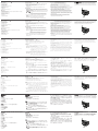
Hardware Installation
B
Rack Mounting
To mount the unit on the front of the rack, do the following:
1. Remove the screws at the front of the unit.
2. Screw the mounting brackets into the front sides of the unit.
3. Slide the unit into the front of the rack and secure it to the rack.
Installation
1. Plug the local console's USB keyboard and mouse, and the DVI connectors
into the unit's console ports. Each port is color coded and marked with an
appropriate icon.
Note: 1. USB keyboards and mice can plug into the USB ports on the front
panel, as well as into the ports in the console port section.
2. The KVM over IP switch does not support distances that exceed
20 m between itself and the local monitor.
2. Use Cat 5e/6 cable to connect any available KVM port to a KVM Adapter
Cable that is appropriate for the server you are installing.
Note: The distance between the KVM over IP switch and the KVM Adapter
Cable must not exceed the maximum distance specifi ed for the KVM
Adapter Cable you are using.
3. Plug the connectors on the KVM Adapter Cable into the appropriate ports
on the server you are installing.
4. Plug an Ethernet cable from the LAN into the KVM over IP switches’ Primary
LAN port.
5. (Optional) Plug another Ethernet cable from the LAN into the KVM over IP
switches’ Secondary LAN port.
6. (Optional) Use a grounding wire to ground the unit by connecting one end
of the wire to the grounding terminal and the other end of the wire to a
suitable grounded object.
7. Plug the power cord(s) supplied with this package into the switch's power
socket(s), and then into an AC power source. When using a single power
socket, be sure to turn on the correct power switch. When using both
power sockets, either of the power switches can be used to turn on the
KVM switch, or turn on both power switches to enable dual power.
8. After the KN2124VA / KN2140VA / KN4124VA / KN4140VA is cabled up
you can turn on the power. After the switch powers on, you can turn on the
servers.
Securing the Cables
For additional safety, use ATEN Lok-U-Plug cable holders to secure the power
cord. Secure the cable holders using the specially designed holes around the
individual power sockets. (See the KN2124VA / KN2140VA / KN4124VA /
KN4140VA user manual for more details.)
B
Package Contents
1 KN2124VA
/
KN2140VA
/
KN4124VA
/
KN4140VA KVM over IP Switch
2 Power Cords
1 Mounting Kit
Hardware Installation
© Copyright 2016 ATEN
®
International Co., Ltd.
ATEN and the ATEN logo are trademarks of ATEN International Co., Ltd. All rights reserved. All
other trademarks are the property of their respective owners.
This product is RoHS compliant.
Part No. PAPE-1223-F00G Printing Date:04/2016
KVM over IP Switch
Quick Start Guide
KN2124VA / KN2140VA /
KN4124VA / KN4140VA
KN2124VA / KN2140VA / KN4124VA / KN4140VA KVM over IP Switch Quick Start Guide
www.aten.com
Commutateur KVM sur IP KN2124VA / KN2140VA / KN4124VA / KN4140VA KVM – Guide de démarrage rapide
www.aten.com
KN2124VA / KN2140VA / KN4124VA / KN4140VA KVM over IP-Switch Kurzanleitung
www.aten.com
Conmutador KVM sobre IP KN2124VA / KN2140VA / KN4124VA / KN4140VA Guía rápida
www.aten.com
Switch KVM over IP KN2124VA / KN2140VA / KN4124VA / KN4140VA – Guida rapida
www.aten.com
ATEN Altusen
™
Important Notice
Considering environmental protection, ATEN does not provide a fully
printed user manual for this product. If the information contained in the
Quick Start Guide is not enough for you to confi gure and operate your
product, please visit our website www.aten.com, and download
the full user manual.
Online Registration
http://eservice.aten.com
Technical Phone Support
International:
886-2-86926959
All information, documentation, firmware, software utilities, and
specifi cations contained in this package are subject to change without
prior notification by the manufacturer. Please visit our website http://
www.aten.com/download/?cid=dds for the most up-to-date versions.
이 기기는 업무용(A급) 전자파 적합기기로서 판매자 또는 사용자는 이점
을 주의하시기 바라며, 가정외의 지역에서 사용하는 것을 목적으로합니다.
The following contains information that relates to China:
Rack Mounting
Installation
North America:
1-888-999-ATEN Ext: 4988
United Kingdom:
44-8-4481-58923
EMC Information
FEDERAL COMMUNICATIONS COMMISSION INTERFERENCE STATEMENT:
This equipment has been tested and found to comply with the limits for a Class A
digital device, pursuant to Part 15 of the FCC Rules. These limits are designed to provide
reasonable protection against harmful interference when the equipment is operated
in a commercial environment. This equipment generates, uses, and can radiate radio
frequency energy and, if not installed and used in accordance with the instruction
manual, may cause harmful interference to radio communications. Operation of this
equipment in a residential area is likely to cause harmful interference in which case the
user will be required to correct the interference at his own expense.
FCC Caution: Any changes or modifi cations not expressly approved by the party
responsible for compliance could void the user's authority to operate this equipment.
Warning: This equipment is compliant with Class A of CISPR 32. In a residential
environment this equipment may cause radio interference.
Suggestion: Shielded twisted pair (STP) cables must be used with the unit to ensure
compliance with FCC & CE standards.
This device complies with Part 15 of the FCC Rules. Operation is subject to the following
two conditions:(1) this device mat not cause harmful interference, and(2) this device
must accept any interference received, including interference that may cause undesired
operation.
Front View
(KN2124VA / KN4124VA)
Front View
(KN2140VA / KN4140VA)
Rear View
(KN2124VA / KN4124VA)
Rear View
(KN2140VA / KN4140VA)
2 Lok-U-Plugs
1 Lok-U-Plug Installation Tool
1 Foot Pad Set (4 pcs.)
1 User Instructions
(1) (2)
Description de l’appareil
A
Vue avant
1. Voyants d’alimentation (Power)
2. Voyants des ports
3. Voyants LAN
4. Port de console USB pour ordinateur portable (LUC)
5. Ports USB
6. Bouton de réinitialisation
7. Ports audio
8. Boutons de changement de port
Vue arrière
1. Prises d’alimentation (avec orifi ces pour supports de câble Lok-U-Plug)
2. Interrupteurs d’alimentation
3. Port LAN secondaire
4. Port LAN principal
5. Ports de console locaux
6. Ports KVM
7. Prise de terre
Installation du matériel
B
Montage sur bâti
Pour monter l'appareil à l'avant du bâti, procédez comme suit :
1. Retirez les vis situées à l’avant de l’appareil.
2. Vissez les supports de fi xation sur les côtés avant de l’appareil.
3. Faites glisser l'appareil dans l'avant du bâti et fi xez-le au bâti.
IInstallation
1. Branchez le clavier et la souris USB de la console locale, et les connecteurs
DVI dans les ports de console de l’appareil. Chaque port est identifi é par un
code couleur et une icône correspondante.
Remarque : 1. Les claviers et souris USB peuvent être branchés sur les ports
USB situés à l'avant de l'appareil, ainsi que sur les ports de la
section des ports de console situés à l'arrière
2. La distance entre le commutateur KVM sur IP et le moniteur
local ne doit pas dépasser 20 m.
2. Utilisez un câble de catégorie 5e/6 pour connecter un port KVM disponible
à un câble adaptateur KVM adapté au serveur que vous installez.
Remarque : la distance entre le commutateur KVM sur IP et le câble
adaptateur KVM ne doit pas dépasser la distance maximale
spécifi ée pour le câble adaptateur KVM que vous utilisez.
3. Branchez les connecteurs du câble adaptateur KVM sur les ports appropriés
du serveur que vous installez.
4. Branchez un câble Ethernet entre le réseau LAN et le port LAN principal des
commutateurs KVM sur IP.
5. (Facultatif) Branchez un autre câble Ethernet entre le réseau LAN et le port
LAN secondaire des commutateurs KVM sur IP.
6. (Facultatif) Pour mettre l’unité à la terre, reliez une extrémité du câble à la
borne de terre et l'autre extrémité à un objet correctement mis à la terre.
7. Reliez le(s) câble(s) d'alimentation fourni(s) à la(les) prise(s) d'alimentation
du commutateur, puis à une prise de courant CA. Lorsque vous utilisez une
prise d’alimentation unique, assurez-vous d’actionner le bon interrupteur.
Lorsque vous utilisez deux prises d’alimentation, n’importe lequel des
deux interrupteurs peut être utilisé pour actionner le commutateur KVM;
vous pouvez également actionner les deux interrupteurs pour activer
l’alimentation double.
8. Une fois le KN2124VA / KN2140VA / KN4124VA / KN4140VA correctement
branché, vous pouvez l'allumer. Une fois qu’il est allumé, vous pouvez
mettre les serveurs sous tension.
Fixation des câbles
Pour plus de sécurité, utilisez des supports de câble Lok-U-Plug ATEN pour fi xer
les câbles. Fixez les supports de câble en utilisant les orifi ces prévus à cet effet
autour des différentes prises d‘alimentation. (Plus plus de détails, consultez le
manuel d’utilisation des commutateurs KN2124VA / KN2140VA / KN4124VA /
KN4140VA.)
Hardwareübersicht
A
Vorderseitige Ansicht
1. LED-Betriebsanzeigen
2. Port-LEDs
3. LAN-LED-Anzeigen
4. Laptop-USB-Konsolport (LUC)
5. USB-Ports
6. Schalter zum Zurücksetzen
7. Audioports
8. Portumschalter-Tasten
Rückseitige Ansicht
1. Netzeingangsbuchsen (mit Löchern für die Lok-U-Plug-Kabelhalter)
2. Netzschalter
3. Zweiter LAN-Port
4. Erster LAN-Port
5. Lokale Konsolports
6. KVM-Ports
7. Erdungsanschluss
Presentación del hardware
A
Vista frontal
1. Indicadores de alimentación
2. Indicadores LED de los puertos
3. Indicadores LAN
4. Puerto de consola de computadora portátil (LUC)
5. Puertos USB
6. Interruptor de reseteo
7. Puertos de audio
8. Botones de conmutación entre puertos
Vista posterior
1. Entradas de alimentación (con agujeros para sujetadores de cables Lok-U-
Plug)
2. Interruptores de alimentación
3. Puerto LAN secundario
4. Puerto LAN primario
5. Puertos de consola local
6. Puertos KVM
7. Toma de tierra
Hardware
A
Vista anteriore
1. LED d’alimentazione
2. LED delle
po
rte
3. LED LAN
4. Porta USB di collegamento alla console laptop (LUC)
5. Porte USB
6. Interruttore di ripristino
7. Porte audio
8. Pulsanti del cambiamento di porta
Vista posteriore
1. Prese d’alimentazione (con fori per i fermacavi Lok-U-Plug)
2. Interruttori di alimentazione
3. Porta LAN secondaria
4. Porta LAN primaria
5. Porte console locale
6. Porte KVM
7. Terminale di messa a terra
Hardware installieren
B
Rack-Montage
Um das Gerät vorne im Rack einzubauen, gehen Sie folgendermaßen vor:
1. Lösen und entfernen Sie die Schrauben von der Vorderseite.
2. Schrauben Sie die Montagehalterungen an die Vorderseiten des
Gerätegehäuses.
3. Schieben Sie das Gerät von vorne in das Rack und schrauben es fest.
Installation
1. Verbinden Sie die Stecker der USB-Tastatur und -Maus sowie den DVI
Stecker der lokalen Konsole mit den Konsolenports des Gerätes. Jede
Buchse ist durch ein entsprechendes Symbol sowie farblich gekennzeichnet.
Hinweis: 1. USB-Tastaturen und –Mäuse können bequem an die USB-
Anschlüsse der Vorderseite angeschlossen wenden, aber bei
Bedarf auch an die des Konsolportabschnitts.
2. Die maximale Entfernung zwischen dem KVM over IP-Switch
und dem lokalen Monitor beträgt 20 m.
2. Verbinden Sie einen beliebigen KVM-Port mit einem KVM-Adapterkabel, das
für den anzuschließenden Server geeignet ist. Verwenden Sie dazu ein Kat.
5e/6-Kabel.
Hinweis: Die maximale Entfernung zwischen dem KVM over IP-Switch und
dem KVM-Adapterkabel darf die maximal zulässige für das KVM-
Adapterkabel angegebene Entfernung nicht überschreiten.
Instalar el hardware
B
Montaje en rack
Para montar la unidad en la parte frontal del rack, haga lo siguiente:
1. Retire los tornillos de la parte frontal de la unidad.
2. Atornille las escuadras de montaje en los laterales delanteros de la unidad.
3. Deslice la unidad en la parte frontal del rack y fíjela al rack.
Instalación
1. Conecte los cables del teclado y mouse USB así como DVI locales a los
puertos de consola local de la unidad. Cada puerto lleva el código de color
estándar, además de un icono para su identifi cación.
Nota: 1. Los teclados y mouses USB se pueden conectar a los puertos USB
situados en el panel frontal de la unidad así como a los puertos de
la sección de consola local situados en el panel posterior.
2. La distancia máxima entre el conmutador KVM sobre IP y el
monitor local no debe exceder los 20 m.
2. Conecte cualquier puerto KVM disponible al cable adaptador KVM
adecuado para el servidor que vaya a instalar. Para ello, use un cable de
categoría 5e/6.
Nota: La distancia entre el conmutador KVM sobre IP y el cable adaptador
KVM no debe exceder la distancia máxima especifi cada para el cable
adaptador KVM que esté empleando.
Installazione dell'hardwaree
B
Montaggio in rack
Per montare il dispositivo nel lato anteriore del rack, procedere come segue:
1. Rimuovere le due viti poste sul davanti dell’unità.
2. Avvitare le staffe per il montaggio sul lati anteriori dell’unità.
3. Far scivolare il dispositivo nella parte anteriore del rack e fi ssarlo ad esso.
Installazione
1. Collegare mouse e tastiera USB e i connettori DVI della console locale alle
rispettive porte dell’unità. Ogni porta è contrassegnata da un colore e da
un’icona appropriata.
Nota: 1. È possibile inserire mouse e tastiere USB nelle porte USB sul lato
anteriore oppure nelle porte della sezione console.
2. La distanza tra lo switch KVM over IP e il monitor locale non deve
superare i 20 metri.
2. Utilizzare un cavo Cat 5e/6 per collegare qualsiasi porta KVM disponibile a
un cavo adattatore KVM adeguato al server che si sta confi gurando.
Nota: la distanza tra lo switch KVM over IP e il cavo adattatore KVM non
deve superare la distanza massima specifi cata per il cavo adattatore
KVM utilizzato.
3. Inserire i connettori del cavo dell’adattatore KVM nelle porte corrispondenti
del server che si sta confi gurando.
3. Verbinden Sie den Stecker des KVM-Adapterkabels mit den betreffenden
Ports des anzuschließenden Servers.
4. Verbinden Sie ein Ethernet-Kabel von Ihrem lokalen Netzwerk mit dem
ersten LAN-Port des KVM over IP-Switches.
5. (Optional) Verbinden Sie ein weiteres Ethernet-Kabel von Ihrem lokalen
Netzwerk mit dem zweiten LAN-Port des KVM over IP-Switches.
6. (Optional) Erden Sie die Einheit mithilfe eines Erdleiters. Verbinden Sie dazu
das eine Ende des Leiters mit der Erdungsschelle und das andere Ende mit
einem geerdeten Gegenstand.
7. Verbinden Sie das bzw. die mitgelieferte(n) Netzkabel mit der
Stromeingangsbuchse am Switch und dem Stromnetz. Wenn Sie eine
einzige Netzeingangsbuchse anschließen, achten Sie darauf, dass Sie den
richtigen Netzschalter einschalten. Bei Verwendung beider Netzeingänge
können Sie einen beliebigen Netzschalter verwenden, um den KVM-
Switch einzuschalten. Oder schalten Sie sie beide ein, um eine duale
Stromversorgung zu gewährleisten.
8. Nachdem der KN2124VA / KN2140VA / KN4124VA / KN4140VA verkabelt
wurde, können Sie ihn einschalten. Nachdem der Switch eingeschaltet
wurde, können Sie auch die angeschlossenen Server einschalten.
3. Enchufe los conectores del cable adaptador KVM a los puertos
correspondientes del servidor que quiera instalar.
4. Conecte un cable Ethernet de la red local al puerto LAN primario del
conmutador KVM sobre IP.
5. (Opcional) Conecte otro cable Ethernet de la red local al puerto LAN
secundario del conmutador KVM sobre IP.
6. (Opcional) Emplee un conductor de tierra para conectar la unidad a tierra.
Para ello, conecte un extremo del conductor al terminal de tierra del equipo
y el otro extremo a un objeto ya puesto a tierra.
7. Conecte el/los cable(s) de alimentación incluido(s) a la entrada de
alimentación del conmutador y luego a una toma eléctrica. Si solo quiere
conectar una toma eléctrica, deberá encender el equipo con el interruptor
de alimentación adecuado. Si lo conecta a dos tomas, cualquiera de los
interruptores de alimentación servirá para encender el conmutador KVM. O
encienda los dos para obtener una alimentación doble.
8. Una vez conectado el conmutador KN2124VA / KN2140VA / KN4124VA /
KN4140VA, puede encenderlo. A continuación, encienda los servidores.
4. Collegare la LAN alla porta LAN primaria degli switch KVM over IP mediante
un cavo Ethernet.
5. (Opzionale) Collegare la LAN alla porta LAN secondaria degli switch KVM
over IP mediante un cavo Ethernet.
6. (Opzionale) Utilizzare un fi lo apposito per mettere a terra l’unità collegando
un’estremità del fi lo a terminale di messa a terra e l’altra estremità a un
oggetto dotato di adeguata messa a terra.
7. Collegare i(l) cavo/i di alimentazione fornito/i insieme a questa confezione
nella/e presa/e di alimentazione dello switch e quindi all’alimentazione
CA. Se si utilizza un'unica presa d'alimentazione, assicurarsi di accendere
l'interruttore corretto. Se si utilizzano entrambe le prese, è possibile
utilizzare uno qualsiasi degli interruttori per accendere lo switch KVM
oppure entrambi per attivare la doppia alimentazione.
8. Una volta collegato il KN2124VA / KN2140VA / KN4124VA / KN4140VA,
accendere l’alimentazione. Una volta acceso il dispositivo è possibile
accendere i server.
A
Hardware Review
La pagina si sta caricando...
-
 1
1
-
 2
2


ATEN Altusen KN2124VA Guida Rapida
- Categoria
- Switch di rete
- Tipo
- Guida Rapida
in altre lingue
- English: ATEN Altusen KN2124VA Quick start guide
- français: ATEN Altusen KN2124VA Guide de démarrage rapide
- español: ATEN Altusen KN2124VA Guía de inicio rápido
- Deutsch: ATEN Altusen KN2124VA Schnellstartanleitung
- русский: ATEN Altusen KN2124VA Инструкция по началу работы
- português: ATEN Altusen KN2124VA Guia rápido
- 日本語: ATEN Altusen KN2124VA クイックスタートガイド
