Lincoln Electric POWER MIG 180 Istruzioni per l'uso
- Categoria
- Sistema di saldatura
- Tipo
- Istruzioni per l'uso

IM2012
05/2008
Rev. 2
POWER MIG 180C (CE)
OPERATOR’S MANUAL
MANUALE OPERATIVO
BEDIENUNGSANLEITUNG
MANUAL DE INSTRUCCIONES
MANUEL D'UTILISATION
BRUKSANVISNING OG DELELISTE
GEBRUIKSAANWIJZING
BRUKSANVISNING
INSTRUKCJA OBSŁUGI
KÄYTTÖOHJE
THE LINCOLN ELECTRIC COMPANY
22801 Saint Clair Ave. ,Cleveland, OH USA 44117-1199
www.lincolnelectric.com
LINCOLN ELECTRIC EUROPE S.L
c/o Balmes, 89 - 8
0
2
a
, 08008 Barcelona, Spain
www.lincolnelectric.eu

II

III
07/06
English
Do not dispose of electrical equipment together with normal waste!
In observance of European Directive 2002/96/EC on Waste Electrical and Electronic Equipment (WEEE) and its
implementation in accordance with national law, electrical equipment that has reached the end of its life must be
collected separately and returned to an environmentally compatible recycling facility. As the owner of the
equipment, you should get information on approved collection systems from our local representative.
By applying this European Directive you will protect the environment and human health!
Italiano
Non gettare le apparecchiature elettriche tra i rifiuti domestici!
In ottemperanza alla Direttiva Europea 2002/96/CE sui Rifiuti di Apparechiature Elettriche ed Elettroniche (RAEE)
e la sua attuazione in conformità alle norme nazionali, le apparecchiature elettriche esauste devono essere
raccolte separatamente e restituite ad una organizzazione di riciclaggio ecocompatibile. Come proprietario
dell’apparecchiatura, Lei potrà ricevere informazioni circa il sistema approvato di raccolta, dal nostro
rappresentante locale.
Applicando questa Direttiva Europea Lei contribuirà a migliorare l’ambiente e la salute!
Deutsch
Werfen Sie Elektrowerkzeuge nicht in den Hausmüll!
Gemäss Europäischer Richtlinie 2002/96/EG über Elektro- und Elektronik- Altgeräte (Waste Electrical and
Electronic Equipment, WEEE) und Umsetzung in nationales Recht müssen verbrauchte Elektrowerkzeuge
getrennt gesammelt und einer umweltgerechten Wiederverwertung zugeführt werden. Als Eigentümer diese
Werkzeuges sollten sie sich Informationen über ein lokales autorisiertes Sammel- bzw. Entsorgungssystem
einholen.
Mit der Anwendung dieser EU Direktive tragen sie wesentlich zur Schonung der Umwelt und ihrer Gesundheit bei!
Español
No tirar nunca los aparatos eléctricos junto con los residuos en general!.
De conformidad a la Directiva Europea 2002/96/EC relativa a los Residuos de Equipos Eléctricos o Electrónicos
(RAEE) y al acuerdo de la legislación nacional, los equipos eléctricos deberán ser recogidos y reciclados
respetando el medioambiente. Como propietario del equipo, deberá informar de los sistemas y lugares
apropiados para la recogida de los mismos.
Aplicar esta Directiva Europea protegerá el medioambiente y su salud!
Français
Ne pas jeter les appareils électriques avec les déchets ordinaires!
Conformément à la Directive Européenne 2002/96/EC relative aux Déchets d' Équipements Électriques ou
Électroniques (DEEE), et à sa transposition dans la législation nationale, les appareils électriques doivent être
collectés à part et être soumis à un recyclage respectueux de l’environnement. En tant que propriétaire de
l’équipement, vous devriez vous informer sur les systèmes de collecte approuvés auprès nos représentants
locaux.
Appliquer cette Directive Européenne améliorera l’environnement et la santé!
Norsk
Kast ikke elektriske artikler sammen med vanlig søppel.
I følge det europeiske direktivet for Elektronisk Søppel og Elektriske Artikler 2002/96/EC (Waste Electrical and
Electronic Equipment, WEEE) skal alt avfall kildesorteres og leveres på godkjente plasser i følge loven.
Godkjente retur plasser gis av lokale myndigheter.
Ved å følge det europeiske direktivet bidrar du til å bevare naturen og den menskelige helse.
Nederlandse
Gooi elektrische apparatuur nooit bij gewoon afval!
Met inachtneming van de Europese Richtlijn 2002/96/EC met betrekking tot Afval van Elektrische en
Elektronische Apparatuur (Waste Electrical and Electronic Equipment, WEEE) en de uitvoering daarvan in
overeenstemming met nationaal recht, moet elektrische apparatuur, waarvan de levensduur ten einde loopt, apart
worden verzameld en worden ingeleverd bij een recycling bedrijf, dat overeenkomstig de milieuwetgeving
opereert. Als eigenaar van de apparatuur moet u informatie inwinnen over goedgekeurde verzamelsystemen van
onze vertegenwoordiger ter plaatse.
Door het toepassen van deze Europese Richtlijn beschermt u het milieu en ieders gezondheid!
Svenska
Släng inte uttjänt elektrisk utrustning tillsammans med annat avfall!
Enligt Europadirektiv 2002/96/EC ang. Uttjänt Elektrisk och Elektronisk Utrustning (Waste Electrical and
Electronic Equipment, WEEE) och dess implementering enligt nationella lagar, ska elektrisk utrustning som tjänat
ut sorteras separat och lämnas till en miljögodkänd återvinningsstation. Som ägare till utrustningen, bör du skaffa
information om godkända återvinningssystem från dina lokala myndigheter.
Genom att följa detta Europadirektiv bidrar du till att skydda miljö och hälsa!
Polski
Nie wyrzucać osprzętu elektrycznego razem z normalnymi odpadami!
Zgodnie z Dyrektywą Europejską 2002/96/EC dotyczącą Pozbywania się zużytego Sprzętu Elektrycznego i
Elektronicznego (Waste Electrical and Electronic Equipment, WEEE) i jej wprowadzeniem w życie zgodnie z
międzynarodowym prawem, zużyty sprzęt elektryczny musi być składowany oddzielnie i specjalnie utylizowany.
Jako właściciel urządzeń powinieneś otrzymać informacje o zatwierdzonym systemie składowania od naszego
lokalnego przedstawiciela.
Stosując te wytyczne bedziesz chronił środowisko i zdrowie człowieka!
Suomi
Älä hävitä sähkölaitteita sekajätteiden mukana!
Noudatettaessa Euroopan Unionin Direktiiviä 2002/96/EY Sähkölaite- ja Elektroniikkajätteestä ( WEEE ) ja
toteutettaessa sitä sopusoinnussa kansallisen lain kanssa, sähkölaite, joka on tullut elinkaarensa päähän pitää
kerätä erilleen ja toimittaa sähkö- ja elektroniikkaromujen keräyspisteeseen. Lisätietoja tämän tuotteen
käsittelystä, keräämisestä ja kierrätyksestä saa kunnan ympäristöviranomaisilta.
Noudattamalla tätä Euroopan Unionin direktiiviä, autat torjumaan kielteiset ynpäristö- ja terveysvaikutukset!

IV
12/05
THANKS! For having choosen the QUALITY of the Lincoln Electric products.
• Please Examine Package and Equipment for Damage. Claims for material damaged in shipment must be notified
immediately to the dealer.
• For future reference record in the table below your equipment identification information. Model Name, Code & Serial
Number can be found on the machine rating plate.
GRAZIE! Per aver scelto la QUALITÀ dei prodotti Lincoln Electric.
• Esamini Imballo ed Equipaggiamento per rilevare eventuali danneggiamenti. Le richieste per materiali danneggiati dal
trasporto devono essere immediatamente notificate al rivenditore.
• Per ogni futuro riferimento, compilare la tabella sottostante con le informazioni di identificazione equipaggiamento.
Modello, Codice (Code) e Matricola (Serial Number) sono reperibili sulla targa dati della macchina.
VIELEN DANK! Dass Sie sich für ein QUALITÄTSPRODUKT von Lincoln Electric entschieden haben.
• Bitte überprüfen Sie die Verpackung und den Inhalt auf Beschädigungen. Transportschäden müssen sofort dem Händler
gemeldet werden.
• Damit Sie Ihre Gerätedaten im Bedarfsfall schnell zur Hand haben, tragen Sie diese in die untenstehende Tabelle ein.
Typenbezeichnung, Code- und Seriennummer finden Sie auf dem Typenschild Ihres Gerätes.
GRACIAS! Por haber escogido los productos de CALIDAD Lincoln Electric.
• Por favor, examine que el embalaje y el equipo no tengan daños. La reclamación del material dañado en el transporte
debe ser notificada inmediatamente al proveedor.
• Para un futuro, a continuación encontrará la información que identifica a su equipo. Modelo, Code y Número de Serie los
cuales pueden ser localizados en la placa de características de su equipo.
MERCI! Pour avoir choisi la QUALITÉ Lincoln Electric.
• Vérifiez que ni l’équipement ni son emballage ne sont endommagés. Toute réclamation pour matériel endommagé doit
être immédiatement notifiée à votre revendeur.
• Notez ci-dessous toutes les informations nécessaires à l’identification de votre équipement. Le nom du Modèle ainsi que
les numéros de Code et Série figurent sur la plaque signalétique de la machine.
TAKK! For at du har valgt et KVALITETSPRODUKT fra Lincoln Electric.
• Kontroller emballsjen og produktet for feil eller skader. Eventuelle feil eller transportskader må umiddelbart rapporteres
dit du har kjøpt din maskin.
• For fremtidig referanse og for garantier og service, fyll ut den tekniske informasjonen nedenfor i dette avsnittet. Modell
navn, Kode & Serie nummer finner du på den tekniske platen på maskinen.
BEDANKT! Dat u gekozen heeft voor de KWALITEITSPRODUCTEN van Lincoln Electric.
• Controleert u de verpakking en apparatuur op beschadiging. Claims over transportschade moeten direct aan de dealer of
aan Lincoln electric gemeld worden.
• Voor referentie in de toekomst is het verstandig hieronder u machinegegevens over te nemen. Model Naam, Code &
Serienummer staan op het typeplaatje van de machine.
TACK! För att ni har valt en KVALITETSPRODUKT från Lincoln Electric.
• Vänligen kontrollera förpackning och utrustning m.a.p. skador. Transportskador måste omedelbart anmälas till
återförsäljaren eller transportören.
• Notera informationen om er utrustnings identitet i tabellen nedan. Modellbeteckning, code- och serienummer hittar ni på
maskinens märkplåt.
DZIĘKUJEMY! Za docenienie JASKOŚCI produktów Lincoln Electric.
• Proszę sprawdzić czy opakownie i sprzęt nie są uszkodzone. Reklamacje uszkodzeń powstałych podczas transportu
muszą być natychmiast zgłoszone do dostawcy (dystrybutora).
• Dla ułatwienia prosimy o zapisanie na tej stronie danych identyfikacyjnych wyrobów. Nazwa modelu, Kod i Numer
Seryjny, które możecie Państwo znaleźć na tabliczce znamionowej wyrobu.
KIITOS! Kiitos, että olet valinnut Lincoln Electric LAATU tuotteita.
• Tarkista pakkaus ja tuotteet vaurioiden varalta. Vaateet mahdollisista kuljetusvaurioista on ilmoitettava välittömästi
jälleenmyyjälle.
• Tulevaisuutta varten täytä alla oleva lomake laitteen tunnistusta varten. Mallin, Koodin ja Sarjanumeron voit löytää
konekilvestä.
Model Name, Modello, Typenbezeichnung, Modelo, Nom du modèle, Modell navn, Model Naam, Modellbeteckning, Nazwa
modelu, Mallinimi:
………………...…………………………….…………………………………………………………………………………………..
Code & Serial number, Code (codice) e Matricola, Code- und Seriennummer, Code y Número de Serie, Numéros de Code et
Série, Kode & Serie nummer, Code en Serienummer, Code- och Serienummer, Kod i numer Seryjny, Koodi ja Sarjanumero:
………………….……………………………………………….. …………………………………………………….……………..
Date & Where Purchased, Data e Luogo d’acquisto, Kaufdatum und Händler, Fecha y Nombre del Proveedor, Lieu et Date
d’acquisition, Kjøps dato og Sted, Datum en Plaats eerste aankoop, Inköpsdatum och Inköpsställe, Data i Miejsce zakupu,
Päiväys ja Ostopaikka:
…………………………………………………………………... ……………………….…………………………………………..

V
ENGLISH INDEX
Safety.................................................................................................................................................................................................... A-1
Installation and Operator Instructions ................................................................................................................................................... A-2
Electromagnetic Compatibility (EMC) ................................................................................................................................................... A-9
Technical Specifications ....................................................................................................................................................................... A-9
INDICE ITALIANO
Sicurezza .............................................................................................................................................................................................. B-1
Installazione e Istruzioni Operative....................................................................................................................................................... B-2
Compatibilità Elettromagnetica (EMC).................................................................................................................................................. B-9
Specifiche Tecniche.............................................................................................................................................................................. B-9
INHALTSVERZEICHNIS DEUTSCH
Sicherheitsmaßnahmen / Unfallschutz .................................................................................................................................................C-1
Installation und Bedienungshinweise.................................................................................................................................................... C-2
Elektromagnetische Verträglichkeit (EMV) ........................................................................................................................................... C-9
Technische Daten............................................................................................................................................................................... C-10
INDICE ESPAÑOL
Seguridad.............................................................................................................................................................................................. D-1
Instalación e Instrucciones de Funcionamiento.................................................................................................................................... D-2
Compatibilidad Electromagnética (EMC).............................................................................................................................................. D-9
Especificaciones Técnicas.................................................................................................................................................................. D-10
INDEX FRANÇAIS
Sécurité................................................................................................................................................................................................. E-1
Installation et Instructions d'Utilisation.................................................................................................................................................. E-2
Compatibilité Electromagnétique (CEM)............................................................................................................................................... E-8
Caractéristiques Techniques ................................................................................................................................................................ E-9
NORSK INNHOLDSFORTEGNELSE
Sikkerhetsregler.....................................................................................................................................................................................F-1
Installasjon og Brukerinstruksjon ...........................................................................................................................................................F-2
Elektromagnetisk Kompatibilitet (EMC) .................................................................................................................................................F-9
Tekniske Spesifikasjoner .......................................................................................................................................................................F-9
NEDERLANDSE INDEX
Veiligheid ..............................................................................................................................................................................................G-1
Installatie en Bediening.........................................................................................................................................................................G-2
Elektromagnetische Compatibiliteit (EMC) ...........................................................................................................................................G-9
Technische Specificaties ......................................................................................................................................................................G-9
SVENSK INNEHÅLLSFÖRTECKNING
Säkerhetsanvisningar ........................................................................................................................................................................... H-1
Instruktioner för Installation och Handhavande .................................................................................................................................... H-2
Elektromagnetisk Kompatibilitet (EMC) ................................................................................................................................................ H-8
Tekniska Specifikationer....................................................................................................................................................................... H-9
SKOROWIDZ POLSKI
Bezpieczeństwo Użytkowania ................................................................................................................................................................I-1
Instrukcja Instalacji i Eksploatacji ...........................................................................................................................................................I-2
Kompatybilność Elektromagnetyczna (EMC) .........................................................................................................................................I-9
Dane Techniczne..................................................................................................................................................................................I-10
SISÄLLYSLUETTELO
Turvallisuus............................................................................................................................................................................................J-1
Asennus ja Käyttöohjeet ........................................................................................................................................................................J-2
Elektromagneettinen Yhteensopivuus (EMC)........................................................................................................................................J-9
Tekniset Tiedot ......................................................................................................................................................................................J-9
Spare Parts, Parti di Ricambio, Ersatzteile, Lista de Piezas de Recambio, Pièces de Rechange, Deleliste, Reserve Onderdelen,
Reservdelar, Wykaz Części Zamiennych, Varaosaluettelo ......................................................................................................................1
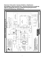
Electrical Schematic, Schema Elettrico, Elektrische Schaltpläne, Esquema Eléctrico, Schéma Electrique, Elektrisk Skjema, Elektrisch
Schema, Elektriskt Kopplingsschema, Schemat Elektryczny, Sähkökaavio ............................................................................................2
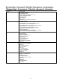
Accessories, Accessori, Zubehör, Accesorios, Accessoires, Tilleggsutstyr, Accessores, Tillbehör, Akcesoria, Varusteet .....................3

A
-1
Safety
11/04
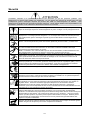
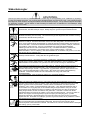
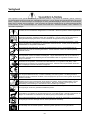
WARNING
This equipment must be used by qualified personnel. Be sure that all installation, operation, maintenance and repair
procedures are performed only by qualified person. Read and understand this manual before operating this equipment.
Failure to follow the instructions in this manual could cause serious personal injury, loss of life, or damage to this
equipment. Read and understand the following explanations of the warning symbols. Lincoln Electric is not responsible
for damages caused by improper installation, improper care or abnormal operation.
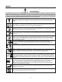
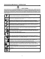
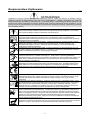
WARNING: This symbol indicates that instructions must be followed to avoid serious personal injury,
loss of life, or damage to this equipment. Protect yourself and others from possible serious injury or
death.
READ AND UNDERSTAND INSTRUCTIONS: Read and understand this manual before operating
this equipment. Arc welding can be hazardous. Failure to follow the instructions in this manual could
cause serious personal injury, loss of life, or damage to this equipment.
ELECTRIC SHOCK CAN KILL: Welding equipment generates high voltages. Do not touch the
electrode, work clamp, or connected work pieces when this equipment is on. Insulate yourself from
the electrode, work clamp, and connected work pieces.
ELECTRICALLY POWERED EQUIPMENT: Turn off input power using the disconnect switch at the
fuse box before working on this equipment. Ground this equipment in accordance with local electrical
regulations.
ELECTRICALLY POWERED EQUIPMENT: Regularly inspect the input, electrode, and work clamp
cables. If any insulation damage exists replace the cable immediately. Do not place the electrode
holder directly on the welding table or any other surface in contact with the work clamp to avoid the
risk of accidental arc ignition.
ELECTRIC AND MAGNETIC FIELDS MAY BE DANGEROUS: Electric current flowing through any
conductor creates electric and magnetic fields (EMF). EMF fields may interfere with some
pacemakers, and welders having a pacemaker shall consult their physician before operating this
equipment.
CE COMPLIANCE: This equipment complies with the European Community Directives.
FUMES AND GASES CAN BE DANGEROUS: Welding may produce fumes and gases hazardous to
health. Avoid breathing these fumes and gases. To avoid these dangers the operator must use
enough ventilation or exhaust to keep fumes and gases away from the breathing zone.
ARC RAYS CAN BURN: Use a shield with the proper filter and cover plates to protect your eyes from
sparks and the rays of the arc when welding or observing. Use suitable clothing made from durable
flame-resistant material to protect you skin and that of your helpers. Protect other nearby personnel
with suitable, non-flammable screening and warn them not to watch the arc nor expose themselves to
the arc.
WELDING SPARKS CAN CAUSE FIRE OR EXPLOSION: Remove fire hazards from the welding
area and have a fire extinguisher readily available. Welding sparks and hot materials from the welding
process can easily go through small cracks and openings to adjacent areas. Do not weld on any
tanks, drums, containers, or material until the proper steps have been taken to insure that no
flammable or toxic vapors will be present. Never operate this equipment when flammable gases,
vapors or liquid combustibles are present.
WELDED MATERIALS CAN BURN: Welding generates a large amount of heat. Hot surfaces and
materials in work area can cause serious burns. Use gloves and pliers when touching or moving
materials in the work area.
SAFETY MARK: This equipment is suitable for supplying power for welding operations carried out in
an environment with increased hazard of electric shock.

A
-2
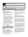
EQUIPMENT WEIGHT OVER 30kg: Move this equipment with care and with the help of another
person. Lifting may be dangerous for your physical health.
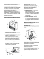
CYLINDER MAY EXPLODE IF DAMAGED: Use only compressed gas cylinders containing the
correct shielding gas for the process used and properly operating regulators designed for the gas and
pressure used. Always keep cylinders in an upright position securely chained to a fixed support. Do
not move or transport gas cylinders with the protection cap removed. Do not allow the electrode,
electrode holder, work clamp or any other electrically live part to touch a gas cylinder. Gas cylinders
must be located away from areas where they may be subjected to physical damage or the welding
process including sparks and heat sources.
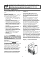
Installation and Operator Instructions
Read this entire section before installation or operation
of the machine.
Location and Environment
The welder POWER MIG 180C (CE) will operate in
harsh environments. Even so, it is important that simple
preventative measures are followed in order to assure
long life and reliable operation.
• Place the machine directly on a secure, level
surface or on a recommended undercarriage. The
machine may topple over if this procedure is not
followed.
• Do not use this machine for pipe thawing.
• The machine must be located where there is free
circulation of clean air such that air movement in the
back, out the sides and bottom will not be restricted.
• Dirt and dust that can be drawn into the machine
should be kept to a minimum. Failure to observe
these precautions can result in excessive operating
temperatures and nuisance shutdown.
• Keep machine dry. Shelter from rain and snow. Do
not place on wet ground or in puddles
.
• This machine has a protection rating of IP21S.
• Locate the machine away from radio controlled
machinery. Normal operation may adversely affect
the operation of nearby radio controlled machinery,
which may result in injury or equipment damage.
Read the section on electromagnetic compatibility in
this manual.
• Do not operate in areas with an ambient
temperature greater than 40°C.
WARNING
DO NOT MOUNT OVER COMBUSTIBLE SURFACES.
Where there is a combustible surface directly under
stationary or fixed electrical equipment, that surface shall
be covered with a steel plate at least 1.6mm thick, which
shall extend not less than 150mm beyond the equipment
on all sides.
Stacking
POWER MIG 180C (CE) cannot be stacked.
Input and Grounding Connections
Only a qualified electrician should connect the Invertec
POWER MIG 180C (CE). Installation should be made in
accordance with the appropriate IEC standards, all local
codes and the information detailed below.
Check the Input Voltage, Phase, and Frequency
supplied to this machine before turning it on. The
allowable Input Voltage is indicated in the technical
specification section of this manual and on the rating
plate of the machine. Be sure that the machine is
grounded.
Make sure the power available at the input connection is
adequate for normal operation of the machine. The fuse
rating and cable sizes are both indicated in the technical
specification section of this manual.
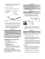
OPERATION
Product Description & Duty Cycle
These small portable wire feed welders are capable of
MIG welding on steel, stainless steel, and aluminum.
They are also capable of flux-cored welding on mild
steel.
MIG welding stands for Metal Inert Gas welding and
requires a separate bottle of shielding gas to protect the
weld until it cools. Appropriate shielding gas based on
the type of material you are welding can be purchased
separately from your local welding gas distributor. MIG
welding is ideal for welding on thinner and clean
materials when a very clean excellent cosmetic looking
weld is required. An example would be automotive body
panels.
Flux-cored Welding does not require separate shielding
gas to protect the weld since the welding wire has
special additives known as flux to protect the weld until it
cools. Flux-cored welding is ideal for medium to thicker
material and if welding on painted or rusty steel. Flux-
cored welding is also ideal in outdoor applications where
windy conditions might blow the MIG shielding gas away
from the weld. Flux-cored welding produces a good
looking weld but does not produce an excellent weld
appearance as MIG welding does.
Your machine includes the necessary items to weld with
either the MIG or the flux-cored welding process on
steel. To weld on stainless steel optional stainless steel
welding wire can be purchased separately. This
machine can weld aluminum using 0.9mm diameter
4043 aluminum welding wire. Since aluminum welding
wire is soft an optional aluminum spool gun is
recommended for best results. A welding Procedure
Decal is located inside machine door to help provide
suggested settings for welding.

A
-3
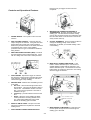
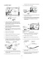
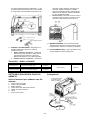
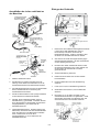
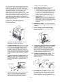
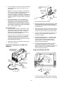
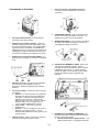
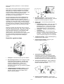
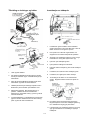
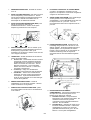
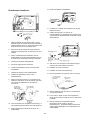
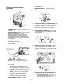
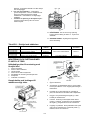
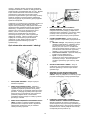
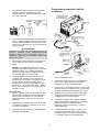
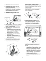
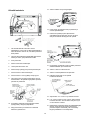
Controls and Operational Features
1. POWER SWITCH: Turns power on and off to the
machine.
2. ARC VOLTAGE CONTROL: This knob sets the
output voltage of the machine. Along with wire feed
speed (WFS) this control sets a weld procedure.
Refer to the procedure decal on the inside wire drive
compartment door to set a correct welding
procedure based on type of material and thickness
being welded.
3. WIRE FEED SPEED CONTROL (WFS): The knob
sets the speed that the machine feeds wire. Along
with arc voltage this control sets a weld procedure.
4. GUN TRIGGER: Depress the trigger to activates
the wire drive to feed wire and energizes the output
of the machine. Depress the trigger to weld and
release the trigger to stop welding.
5. WELDING GUN: Delivers wire and welding current
to the weld.
a. Gun Liner - wire travels through the liner from
the wire drive. The gun liner will feed 0.6mm to
0.9mm wire. The PM180C machine can weld
with 1.1mm wire if an optional 1.1mm liner is
installed in the gun.
b. Contact Tip - provides electrical contact to the
wire.
c. Nozzle - When flux-cored welding the black
nozzle protects the mounting threads on the
gun. When MIG welding the brass nozzle
funnels the shielding gas to the weld.
6. WORK CLAMP & CABLE: Clamps to the work
piece being welded and completes the electrical
welding circuit.
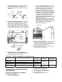
7. GUN TRIGGER CONNECTOR RECEPTACLE:
Plug the 4 pin gun trigger connector into this
receptacle.
8. WELDING GUN CONNECTOR BUSHING &
THUMBSCREW: Provides electrical power to the
welding gun. The thumbscrew holds the welding
gun into the connector block (Front of Machine, Side
Door and Wire Drive Cover have been removed for
clarity of Items 8 and 9).
9. OUTPUT TERMINALS: These connections allow to
change the welding polarity of the machine
depending on whether you are MIG welding or flux-
cored welding.
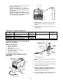
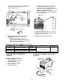
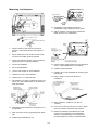
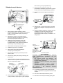
10. WIRE SPOOL SPINDLE AND BRAKE: Turns
Holds a 102mm diameter spool. Use the 51mm
spindle adapter included with the machine to use
203mm diameter spools. The thumbscrew sets the
brake friction to prevent the spool from over rotating
when the trigger is released.
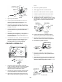
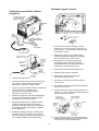
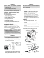
11. WIRE DRIVE & COMPONENTS: Feeds wire from
the wire spool through the drive and through the
welding gun to the weld.

A
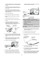
-4
a. Top and Bottom Drive Roll - Drives the wire
through the drive system. The drive roll has a
groove to match the specific wire type and
diam-eter. Refer to Table B.1 for available
drive rolls.
b. Inner & Outer Wire Guide - Guides the wire
between the Top and Bottom Drive Roll and
through the wire drive. The inner guide has a
groove to match a particular wire diameter.
Refer to Table B.1 for available wire guides.
c. Drive Roll Tension Thumbscrew - Turning
clockwise increases the force on the drive rolls
and turning counterclockwise decreases the
force.
12. CIRCUIT BREAKER: If the rated input current of
the machine is exceeded this circuit breaker will trip.
Press to reset.
13. GAS INLET: Shielding gas connects to this inlet.
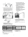
Table B.1: Drive Roll and Wire Guides
Wire Diameter &
Type
Drive Roll Drive Roll Part
Number
Inner Wire Guide Inner Wire Guide
Part Number
0.6mm MIG wire
0.8mm MIG wire
0.6mm/0.8mm Smooth Drive Roll KP2529-1
0.9mm MIG wire 0.9mm Smooth Drive Roll KP2529-2
0.8mm flux-cored
0.9mm flux-cored
0.8mm/1.1mm Knurled Drive Roll KP2529-3
0.6mm-0.9mm Steel Wire Guide KP2531-1
1.1mm flux-cored 0.8mm/1.1mm Knurled Drive Roll KP2529-3 1.1mm Steel Wire Guide KP2531-2
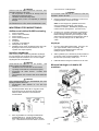
SETTING UP AND MAKING A FLUX-
CORED WELD
Items Needed for Flux Cored Welding
1. 0.9mm Contact Tip
2. 0.6mm-0.9mm wire guide
3. Knurled Drive Roll
4. 0.9mm NR-211MP Flux-Cored Wire
5. Black Flux Cored gun nozzle
6. Welding Gun
7. Work Cable & Clamp
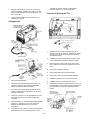
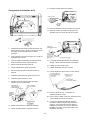
Connect Leads and Cables on the
Machine
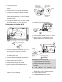
1. Open the case side door.
2. Slide the connector end of the gun and cable
through the hole in the machine front and into the
gun connector bushing on the wire drive.
3. Make sure the gun connector end is seated fully into
the wire drive and tighten the thumbscrew to secure
the gun connector.
4. Plug the gun trigger lead connector into the 4 pin
gun trigger receptacle on the machine front.
5. Wire Drive Polarity. Flux cored welding requires
negative (-) polarity. Connect the short power cable
from the wire drive to the negative (-) output
terminal and tighten the thumbscrew.
6. Work Lead Connection. Slide the lugged end of the
work cable through the hole in the machine front
and place on the positive (+) output terminal and
tighten thumbscrew.

A
-5
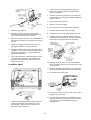
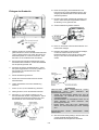
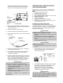
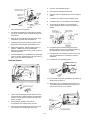
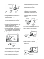
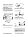
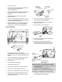
Load Wire Spool
1. Locate the blue labeled 102mm diameter spool of
0.9mm NR-211MP flux-cored wire and place onto
wire spool spindle. Orient the spool so that the wire
feeds off the top of the spool.
2. Secure spool in place by tightening the wing nut
against the against the spacer that holds the wire
spool on the spindle.
3. Open the top drive roll pressure arm by rotating the
tension adjustor arm down and pivoting the drive roll
pressure arm up.
4. Remove the outer wire guide.
5. Slide gun out of drive slightly.
6. Remove the lower drive roll and inner wire guide.
7. Install the 0.6mm-0.9mm inner wire guide.
8. Install the 0.8mm/1.1mm knurled lower drive roll.
9. Carefully unwind and straighten the first six inches
of welding wire from the spool. Do not let the end of
the wire go to prevent the wire from unspooling.
10. Feed the wire through the wire drive inlet along the
inner wire guide groove and into the wire drive outlet
on the gun side.
11. Close the top drive roll pressure arm and secure by
pivoting the tension adjustor back to the up position.
12. Re-install the outer wire guide.
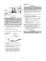
13. Remove the nozzle from the gun and contact tip and
straighten the gun out flat.
14. Turn the machine power to on and depress the gun
trigger to feed the wire through the gun liner until the
wire comes out of the threaded end of the gun
several inches.
15. When trigger is released spool of wire should not
unwind. Adjust wire spool brake accordingly.
16. Install the 0.9mm contact tip.
17. Install the black flux cored welding nozzle to the
gun.
18. Trim the wire stickout to 9.5mm from the contact tip
.
19. Close the case side door. The machine is now
ready to weld.
20. Read "Learn to Weld" (LTW1) that is included with
the machine or watch the "How to Weld" DVD
included with the machine.

A
-6
21. Based on the thickness of the material you are
going to weld and the type and diameter of the
welding wire set the voltage and the wire feed
speed per the procedure decal attached to the
inside of the wire drive compartment door.
WARNING
MOVING PARTS AND ELECTRICAL CONTACT CAN
CAUSE INJURY OR BE FATAL.
• When the gun trigger is depressed drive rolls, spool
of wire and electrode are ELECTRICALLY LIVE
(HOT).
• Keep away from moving parts and pinch points.
• Keep all doors, covers, panels and guards securely
in place.
DO NOT REMOVE OR CONCEAL WARNING LABELS.
SETTING UP AND MAKING A MIG
WELD
Items Needed for Mig Welding
1. 0.6mm Contact Tip
2. 0.6mm-0.9mm wire guide
3. 0.6mmDrive Roll
4. 0.6mm SuperArc L-56 Solid MIG Wire
5. Brass gun nozzle
6. Welding Gun
7. Work Cable & Clamp
8. Gas Regulator & Gas Line
9. Bottle of 75/25 Ar/CO
2
shielding gas (or 100% CO
2
shielding gas) (note this requires a CO
2
regulator
adapter which is sold separately).
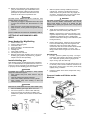
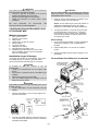
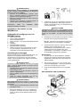
Install shielding gas
MIG welding requires an appropriate bottle of shielding
gas. For mild steel either a cylinder bottle of Ar/CO
2
or
100% CO
2
can be used refer to the following instructions
to properly connect shielding gas to the machine.
WARNING
CYLINDER may explode if damaged. Keep cylinder
upright and chained to support.
• Keep cylinder away from areas where it may be
damaged.
• Never lift welder with cylinder attached.
• Never allow welding electrode to touch cylinder.
• Keep cylinder away from welding or other live
electrical circuits.
WARNING
BUILDUP OF SHIELDING GAS may harm health or kill.
• Shut off shielding gas supply when not in use.
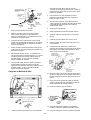
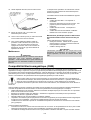
1. Secure the cylinder to a wall or other stationary
support to prevent the cylinder from falling over.
Insulate the cylinder from the work circuit and earth
ground
.
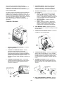
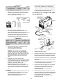
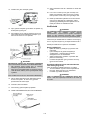
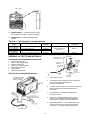
2. With the cylinder securely installed, remove the
cylinder cap. Stand to one side away from the
outlet and open the cylinder valve very slightly for
an instant. This blows away any dust or dirt which
may have accumulated in the valve outlet.
WARNING
BE SURE TO KEEP YOUR FACE AWAY FROM THE
VALVE OUTLET WHEN "CRACKING" THE VALVE.
Never stand directly in front of or behind the flow
regulator when opening the cylinder valve. Always stand
to one side.
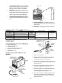
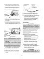
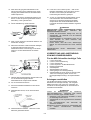
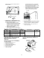
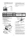
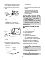
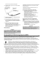
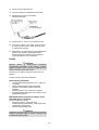
3. Attach the flow regulator to the cylinder valve and
tighten the union nut securely with a wrench.
NOTE: If connecting to 100% CO
2
cylinder, a CO
2
regulator adapter is required. Purchase separately
S19298b CO
2
adapter be sure to install plastic
washer included in the fitting on the bottle side. (See
the Figure above.)
4. Refer to Figure above. Attach one end of inlet gas
hose to the outlet fitting of the flow regulator and
tighten the union nut securely with a wrench.
Connect the other end to the machine Solenoid Inlet
Fitting (5/8-18 female threads - for CGA - 032
fitting). Make certain the gas hose is not kinked or
twisted.
Shielding Gas
1. For CO
2
, open the cylinder very slowly. For argon-
mixed gas, open cylinder valve slowly a fraction of a
turn. When the cylinder pressure gauge pointer
stops moving, open the valve fully.
2. Set gas flow rate for 30 to 40 cubic feet per hour (14
to 18 I/min.) under normal conditions, increase to as
high as 40 to 50 CFH (18 to 23.5 I/min.) under drafty
(slightly windy) conditions.
3. Keep the cylinder valve closed, except when using
the machine.
Connect Leads and Cables on the
Machine

A
-7
1. Open the case side door.
2. Slide the connector end of the gun and cable
through the hole in the machine front and into the
gun connector bushing on the wire drive.
3. Make sure the gun connector end is seated fully into
the wire drive and tighten the thumbscrew to secure
the gun
.
4. Plug the gun trigger lead connector into the 4 pin
gun trigger receptacle on the machine front.
5. Wire Drive Polarity. MIG welding requires positive
(+) polarity. Connect the short power cable from the
wire drive to the positive (+) output terminal and
tighten the thumbscrew.
6. Work Lead Connection. Slide the lugged end of the
work cable through the hole in the machine front
and place on the negative (-) output terminal and
tighten thumbscrew
.
Load Wire Spool
1. Locate the green labeled 102mm diameter spool of
0.6mm L56 Solid MIG wire and place onto wire
spool spindle. Orient the spool so that the wire
feeds off the top of the spool.
2. Secure spool in place by tightening the wing nut
against the against the spacer that holds the wire
spool on the spindle.
3. Open the top drive roll pressure arm by rotating the
tension adjustor arm down and pivoting the drive roll
pressure arm up.
4. Remove the outer wire guide.
5. Slide gun out of drive slightly.
6. Remove the lower drive roll and inner wire guide.
7. Install the 0.6mm-0.9mm inner wire guide.
8. Install the 0.6 mm smooth grooved lower drive roll.
9. Carefully unwind and straighten the first six inches
of welding wire from the spool. Do not let the end of
the wire go to prevent the wire from unspooling.
10. Feed the wire through the wire drive inlet along the
inner wire guide groove and into the wire drive outlet
on the gun side.
11. Close the top drive roll pressure arm and secure by
pivoting the tension adjustor back to the up position.
12. Re-install the outer wire guide.
13. Remove the nozzle from the gun and contact tip and
straighten the gun out flat.
14. Turn the machine power to on and depress the gun
trigger to feed the wire through the gun liner until the
wire comes out of the threaded end of the gun
several inches.

A
-8
WARNING
MOVING PARTS AND ELECTRICAL CONTACT CAN
CAUSE INJURY OR BE FATAL.
• When the gun trigger is depressed drive rolls, spool
of wire and electrode are ELECTRICALLY LIVE
(HOT).
• Keep away from moving parts and pinch points.
• Keep all doors, covers, panels and guards securely
in place.
DO NOT REMOVE OR CONCEAL WARNING LABELS.
15. When trigger is released spool of wire should not
unwind. Adjust wire spool brake accordingly.
16. Install the 0.6mm contact tip.
17. Install the brass gun nozzle to the gun.
18. Trim the wire stickout to 9.5mm from the contact tip
.
19. Close the case side door. The machine is now
ready to weld.
20. Read "Learn to Weld" (LTW1) that is included with
the machine or watch the "How to Weld" DVD
included with the machine.
21. Based on the thickness of the material you are
going to weld and the type and diameter of the
welding wire set the voltage and the wire feed
speed per the procedure decal attached to the
inside of the wire drive compartment door.
Maintenance
WARNING
For any maintenance or repair operations it is
recommended to contact the nearest technical service
center or Lincoln Electric. Maintenance or repairs
performed by unauthorized service centers or personnel
will null and void the manufacturers warranty.
The frequency of the maintenance operations may vary
in accordance with the working environment where the
machine is placed.
Any noticeable damage should be reported immediately.
Routine maintenance (everyday)
• Check cables and connections integrity. Replace, if
necessary.
• Remove the spatters from the welding gun nozzle.
Spatters could interfere with the shielding gas flow
to the arc.
• Check the welding gun condition: replace it, if
necessary.
• Check condition and operation of the cooling fan.
Keep clean its airflow slots.
Periodic maintenance (every 200 working hours
but not more rarely than once a year)
Perform the routine maintenance and, in addition:
• Keep clean the machine. Using a dry ( and low
pressure) airflow, remove the dust from the external
case and from inside of the cabinet.
• Check and tighten all screws.
WARNING
Mains supply network must be disconnected from the
machine before each maintenance and service. After
ach repair, perform proper tests to ensure safety.

A
-9
Electromagnetic Compatibility (EMC)
11/04
This machine has been designed in accordance with all relevant directives and standards. However, it may still generate
electromagnetic disturbances that can affect other systems like telecommunications (telephone, radio, and television) or
other safety systems. These disturbances can cause safety problems in the affected systems. Read and understand
this section to eliminate or reduce the amount of electromagnetic disturbance generated by this machine.
This machine has been designed to operate in an industrial area. To operate in a domestic area it is
necessary to observe particular precautions to eliminate possible electromagnetic disturbances. The
operator must install and operate this equipment as described in this manual. If any electromagnetic
disturbances are detected the operator must put in place corrective actions to eliminate these disturbances
with, if necessary, assistance from Lincoln Electric.
Before installing the machine, the operator must check the work area for any devices that may malfunction because of
electromagnetic disturbances. Consider the following.
• Input and output cables, control cables, and telephone cables that are in or adjacent to the work area and the
machine.
• Radio and/or television transmitters and receivers. Computers or computer controlled equipment.
• Safety and control equipment for industrial processes. Equipment for calibration and measurement.
• Personal medical devices like pacemakers and hearing aids.
• Check the electromagnetic immunity for equipment operating in or near the work area. The operator must be sure
that all equipment in the area is compatible. This may require additional protection measures.
• The dimensions of the work area to consider will depend on the construction of the area and other activities that are
taking place.
Consider the following guidelines to reduce electromagnetic emissions from the machine.
• Connect the machine to the input supply according to this manual. If disturbances occur if may be necessary to take
additional precautions such as filtering the input supply.
• The output cables should be kept as short as possible and should be positioned together. If possible connect the
work piece to ground in order to reduce the electromagnetic emissions. The operator must check that connecting
the work piece to ground does not cause problems or unsafe operating conditions for personnel and equipment.
• Shielding of cables in the work area can reduce electromagnetic emissions. This may be necessary for special
applications.
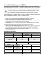
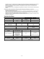
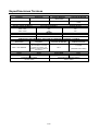
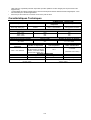
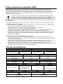
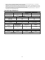
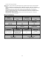
Technical Specifications
INPUT – SINGLE PHASE ONLY
Product Name Ordering Information Standard Voltage
/ Frequency
Input Current
Power Mig 180C (CE) K2661-1
230V ± 10% 50/60Hz
20A @ rated output
RATED OUTPUT AT 40°C
Voltage / Duty Cycle Current Voltage at Related Current
230V / 25%
230V / 60%
230V / 100%
130A
85A
60A
21V
18V
16V
OUTPUT
Welding Current Range Open Circuit Voltage Wire Speed Range
30 - 180A 34V 1.3 - 12.7 m/min
RECOMMENDED INPUT CABLE AND FUSE SIZES
Input Voltage / Frequency Fuse or Breaker Size Input Current Power Cord
230V ± 10% 50/60Hz
16A Super lag
(If connected to a circuit
protected by fuses use Time
Delay Fuse marked "D".)
20 A
3 x 2.5mm
2
(SCHUKO 16A / 250V)
PHYSICAL DIMENSIONS
Height Width Depth Weight
357 mm 285 mm 472 mm 30 kg
Operating Temperature
–10°C to +40°C
Storage Temperature
-25°C to +55°C

B-1
Sicurezza
11/04
AVVERTENZA
Questa macchina deve essere impiegata solo da personale qualificato. Assicuratevi che tutte le procedure di
installazione, impiego, manutenzione e riparazione vengano eseguite solamente da persone qualificate. Leggere e
comprendere questo manuale prima di mettere in funzione la macchina. La mancata osservanza delle istruzioni di
questo manuale può provocare seri infortuni, anche mortali, alle persone, o danni alla macchina. Leggere e
comprendere le spiegazioni seguenti sui simboli di avvertenza. La Lincoln Electric non si assume alcuna responsabilità
per danni conseguenti a installazione non corretta, incuria o impiego in modo anormale.
AVVERTENZA: Questo simbolo indica che occorre seguire le istruzioni per evitare seri infortuni,
anche mortali, alle persone o danni a questa macchina. Proteggete voi stessi e gli altri dalla
possibilità di seri infortuni anche mortali.
LEGGERE E COMPRENDERE LE ISTRUZIONI: Leggere e comprendere questo manuale prima di
far funzionare la macchina. La saldatura ad arco può presentare dei rischi. La mancata osservanza
delle istruzioni di questo manuale può provocare seri infortuni, anche mortali, alle persone o danni alla
macchina.
LA FOLGORAZIONE ELETTRICA E’ MORTALE: Le macchine per saldatura generano tensioni
elevate. Non toccate l’elettrodo, il morsetto di massa o pezzi da saldare collegati alla macchina
quando la macchina è accesa. Mantenetevi isolati elettricamente da elettrodo, morsetto e pezzi
collegati a questo.
MACCHINA CON ALIMENTAZIONE ELETTRICA: Togliere l’alimentazione con l’interruttore ai fusibili
prima di svolgere operazioni su questa macchina. Mettere la macchina a terra secondo le normative
vigenti.
MACCHINA CON ALIMENTAZIONE ELETTRICA: Ispezionare periodicamente i cavi di
alimentazione, all’elettrodo e al pezzo. Se si riscontrano danni all’isolamento sostituire
immediatamente il cavo. Non posare la pinza portaelettrodo direttamente sul banco di saldatura o
qualsiasi altra superficie in contatto con il morsetto di massa per evitare un innesco involontario
dell’arco.
I CAMPI ELETTRICI E MAGNETICI POSSONO ESSERE PERICOLOSI: Il passaggio di corrente
elettrica in un conduttore produce campi elettromagnetici. Questi campi possono interferire con alcuni
cardiostimolatori ("pacemaker") e i saldatori con un cardiostimolatore devono consultare il loro medico
su possibili rischi prima di impiegare questa macchina.
CONFORMITÀ CE: Questa macchina è conforme alle Direttive Europee.
FUMI E GAS POSSONO ESSERE PERICOLOSI: La saldatura può produrre fumi e gas dannosi alla
salute. Evitate di respirare questi fumi e gas. Per evitare il pericolo l’operatore deve disporre di una
ventilazione o di un'estrazione di fumi e gas che li allontanino dalla zona in cui respira.
I RAGGI EMESSI DALL’ARCO BRUCIANO: Usate una maschera con schermatura adatta a
proteggervi gli occhi da spruzzi e raggi emessi dall’arco mentre saldate o osservate la saldatura.
Indossare indumenti adatti in materiale resistente alla fiamma per proteggere il corpo, sia vostro che
dei vostri aiutanti. Le persone che si trovano nelle vicinanze devono essere protette da schermature
adatte, non infiammabili, e devono essere avvertite di non guardare l’arco e di non esporvisi.
GLI SPRUZZI DI SALDATURA POSSONO PROVOCARE INCENDI O ESPLOSIONI: Allontanare
dall'area di saldatura quanto può prendere fuoco e tenere a portata di mano un estintore. Gli spruzzi
o altri materiali ad alta temperatura prodotti dalla saldatura attraversano con facilità eventuali piccole
aperture raggiungendo le zone vicine. Non saldare su serbatoi, bidoni, contenitori o altri materiali fino
a che non si sia fatto tutto il necessario per assicurarsi dell'assenza di vapori infiammabili o nocivi.
Non impiegare mai questa macchina se vi è presenza di gas e/o vapori infiammabili o combustibili
liquidi.
I MATERIALI SALDATI BRUCIANO: Il processo di saldatura produce moltissimo calore. Ci si può
bruciare in modo grave con le superfici e materiali caldi della zona di saldatura. Impiegare guanti e
pinze per toccare o muovere materiali nella zona di saldatura.

B-2
MARCHIO DI SICUREZZA: Questa macchina è adatta a fornire energia per operazioni di saldatura
svolte in ambienti con alto rischio di folgorazione elettrica.
LA MACCHINA PESA OLTRE 30kg. Spostare questa macchina con cura e con l’aiuto di un’altra
persona. Il sollevamento può essere pericoloso per la vostra salute.
LE BOMBOLE POSSONO ESPLODERE SE SONO DANNEGGIATE: Impiegate solo bombole
contenenti il gas compresso adatto al processo di saldatura utilizzato e regolatori di flusso, funzionanti
regolarmente, progettati per il tipo di gas e la pressione in uso. Le bombole vanno tenute sempre in
posizione verticale e assicurate con catena ad un sostegno fisso. Non spostate le bombole senza il
loro cappello di protezione. Evitate qualsiasi contatto dell’elettrodo, della sua pinza, del morsetto di
massa o di ogni altra parte in tensione con la bombola del gas. Le bombole gas vanno collocate
lontane dalle zone dove possano restare danneggiate dal processo di saldatura con relativi spruzzi e
da fonti di calore.
Installazione e Istruzioni Operative
Leggere tutta questa sezione prima di installare e
impiegare la macchina.
Collocazione e ambiente
Questa macchina è in grado di funzionare in ambienti
difficili. E’ comunque importante seguire delle semplici
misure di prevenzione per garantirne una lunga durata e
un funzionamento affidabile.
• Posizionare la macchina direttamente su di una
superfice sicura o carrello raccomandato. La
macchina può cadere se questa procedura non è
corretta.
• Non usare questa macchina per sgelare tubi.
• La macchina deve essere posizionata dove l’aria
puo circolare liberamente nella parte posteriore,
laterale e sul fondo.
• Sporcizia e polvere che possono entrare dentro la
macchina devono essere ridotte al minimo. Il
problema che ne può derivare è incremento della
temperatura di lavoro con relativo intervento della
protezione termica.
• La macchina deve essere tenuta asciutta, protetta
da pioggia o neve; non posizionare su terreno
bagnato o fangoso.
• Questa macchina ha una protezione di grado
IP21S.
• Disponete la macchina lontana da macchinari
controllati via radio. Il suo funzionamento normale
può interferire negativamente sul funzionamento di
macchine controllate via radio poste nelle vicinanze,
con conseguenze di infortuni o danni materiali.
Leggete la sezione sulla compatibilità
elettromagnetica di questo manuale.
• Non impiegate la macchina in zone ove la
temperatura ambiente supera i 40°C.
AVVERTENZA
NON POSIZIONARE SU SUPERFICI COMBUSTIBILI.
Nel caso non si possa evitare questa situazione, sotto la
macchina deve essere presente una lastra di ferro da
almeno 1,6mm di spessore che deve sporgere per non
meno di 150mm da ogni lato della macchina.
Sovrapposizione
La POWER MIG 180C (CE) NON può essere
sovrapposta.
Alimentazione elettrica e collegamento
di terra
Solo personale qualificato può collegare l’Invertec
POWER MIG 180C (CE). L’installazione deve essere
eseguita in accordo con le appropriate normative vigenti
nel paese di installazione, e seguendo le indicazioni
fornite di seguito.
Prima di accendere la macchina controllate Tensione,
Fase e Frequenza di alimentazione. La Tensione di
Alimentazione ammissibile è indicata nella sezione
“Specifiche tecniche” di questo manuale e sulla targa
della macchina. Verificate il collegamento a terra della
macchina.
Assicuratevi che l’alimentazione fornisca una potenza
sufficiente per il funzionamento normale della macchina.
Nella sezione “Specifiche tecniche” di questo manuale
sono indicati i dimensionamenti per fusibili e cavi.
FUNZIONAMENTO
Descrizione Prodotto & Ciclo di Utilizzo
Questa piccola saldatrice portatile a filo è in grado di
eseguire saldature MIG su ferro, acciao inossidabile e
alluminio. È anche in grado di saldare con filo animato
su ferro dolce.
Saldatura MIG significa saldatura di metallo con gas
inerte, e richiede una bombola di gas inerte per
proteggere il bagno di saldatura durante il suo
raffreddamento. L’appropriato gas di saldatura deve
essere scelto in base al tipo di materiale da saldare e
può essere acquistato da qualsiasi distributore di gas
per saldatura. La saldatura MIG è l’ideale per materiali
sottili e puliti, dove è richiesta una componente di estitica
del cordone. Un’esempio può essere per i pannelli delle
automobili.
La saldatura con filo animato non necessita di gas di
protezione separato in quanto il filo include uno speciale
aditivo, conosciuto come flusso, che ha la funzione di
proteggere il cordone durante il raffreddamento. La
saldatura con filo animato è ideale per medi e grandi
spessori su lamiere tinteggiate o ossidate. La saldatura
con fili animati è anche ideale per saldature all’aperto

B-3
dove il vento può vanificare l’effetto del gas di
protezione, allontanandolo dal bagno di saldatura. La
saldatura con filo animato produce un cordone
esteticamente accettabile ma non eccellente come può
fornire la saldatura MIG.
La vostra macchina include tutte le parti necessarie per
saldare sia in MIG che con filo animato su ferro. Per
saldare acciao inossidabile è necessario un altro tipo di
filo che può essere acquistato separatamente. Questa
macchina può saldare alluminio usando filo tipo 4043 da
0,9mm di diametro. Un adesivo con i settaggi
raccomandati è applicato all’interno del pannello del
generatore.
Controlli e Funzioni
1. INTERRUTTORE ALIMENTAZIONE: Accende e
spegne il generatore.
2. CONTROLLO TENSIONE D’ARCO: Questa
manopola regola la tensione di uscita del
generatore. Insieme alla velocità del filo (WFS)
questa regolazione fissa la procedura di saldatura.
Prendere come riferimento l’adesivo all’interno dello
sportello del generatore per regolare i corretti
parametri in base al tipo di materiale e spessore da
saldare.
3. CONTROLLO VELOCITA’ FILO: La manopola
regola la velocità di avanzamento del filo. Insieme
alla tensione d’arco questa regolazione fissa la
procedura di saldatura.
4. PULSANTE TORCIA: Premere il pulsante per
attivare l’avanzamento del filo ed energizzare
l’uscita del generatore. Premere il pulsante per
saldare e rilasciarlo per terminare la saldatura.
5. TORCIA DI SALDATURA: Fornisce filo e corrente
per la saldatura.
a. Guaina – Il filo scorre attraverso la guaina
spinto dal rullino di traino. La guaina della
torcia permette il passaggio di fili da 0,6mm a
0,9mm. La PM180C può saldare con fili sino a
1,1mm con guaina opzionale installata nella
torcia da 1,1mm.
b. Punta di contatto – Fornisce il contatto
elettrico al filo.
c. Ugello – Quando si salda con filo animato
l’ugello nero protegge la torcia dagli spruzzi.
Quando si salda in MIG l’ugello di ottone
indirizza il gas di protezione sulla saldatura.
6. CAVO MASSA E PINZA: Collegare la pinza al
pezzo da saldare per completare il collegamento del
circuito elettrico.
7. CONNETTORE PULSANTE TORCIA: Innestare il
connettore a 4 pin a questa presa.
8. CONNESSIONE TORCIA : Fornisce collegamento
elettrico alla torcia di saldatura. La vite a farfalla
fissa la torcia al corpo trainafilo (La parte frontale, il
pannello laterale e la copertura del gruppo traino
sono stati rimossi per facilitare la visione degli item
8 e 9).
9. TERMIMALI DI USCITA: Queste connessioni
permettono di invertire la polarità della macchina
dipendentemente se si vuole saldare in MIG o Filo
Animato.
10. ASPO PORTABOBINA E FRIZIONE: Utilizzare
l’adattatore da 51mm incluso con la macchina

B-4
per usare bobine da 203mm di diametro. La vite
a farfalla regola la frizione per evitare che la bobina
si svolga quando viene rilasciato il pulsante torcia.
11. GUIDAFILO E COMPONENTI: Alimenta il filo di
saldatura dalla bobina attraverso i rullini ed
attraverso la torcia.
a. Rullino superiore ed inferiore – Guida il filo
attraverso il gruppo trainafilo. Il rullino ha una
gola specifica per il diametro e tipo di filo.
Riferirsi alla tabella B.1 per i rullini disponibili.
b. Guidafilo inferiore e superiore - Guida il filo
attraverso il rullino superiore ed inferiore ed
attraverso il gruppo trainafilo. Il guidafilo
inferiore ha una gola specifica a seconda del
diamtero di filo utilizzato. Riferirsi alla tabella
B:1 per i guidafili disponibili.
c. Pressore rullini – Ruotando in senso orario si
aumenta la forza sui rullini, ruotando in senso
antiorario si diminuisce la forza su di essi.
12. MAGNETOTERMICO: Se la corrente assorbita
dalla macchina supera la corrente nominale questo
magnetotermico interverrà. Premerlo per riattivarlo.
13. COLLEGAMENTO GAS: Il gas di protezione deve
essere collegato a questo portagomma.
Tabella B.1: Rullini e Guidafili
Diametro e tipo filo Rullini Codice rullini Guidafilo Codice guidafilo
0.6mm Filo pieno
0.8mm Filo pieno
0.6mm/0.8mm Rullino liscio KP2529-1
0.9mm Filo pieno 0.9mm Rullino liscio KP2529-2
0.8mm Filo animato
0.9mm Filo animato
0.8mm/1.1mm Rullino zigrinato KP2529-3
0.6mm-0.9mm KP2531-1
1.1mm Filo animato 0.8mm/1.1mm Rullino zigrinato KP2529-3 1.1mm KP2531-2
SETTAGGI E SALDATURA CON FILO
ANIMATO
Articoli necessari per saldatura con filo
animato
1. 0.9mm Punta di contatto
2. 0.6mm-0.9mm Guidafilo
3. Rullino zigrinato
4. 0.9mm NR-211MP Bobina filo animato
5. Ugello nero per filo animato
6. Torcia
7. Pinza e cavo massa
Collegamenti

B-5
1. Aprire il pannello laterale.
2. Inserire la parte terminale della torcia ed il cavo
attraverso l’apertura sul pannello frontale nella
boccola presente sul blocco trainafilo.
3. Assicurarsi che la parte terminale della torcia sia
inserita completamente nella sede e che la vite di
fissaggio sia serrata.
4. Inserire il connettore a 4 poli del pulsante torcia nel
connettore femmina sul pannello frontale della
macchina.
5. Polarità trainafilo. La saldatura con filo animato
necessita la polarità negativa (-). Collegare il cavo
corto dal gruppo traino al terminale negativo (-) e
serrarlo fortemente.
6. Connessione cavo massa. Inserire l’occhiello della
parte terminale del cavo massa attraverso il foro
presente sul pannello frontale e collegarlo al
terminale positivo (+) e serrarlo fortemente.
CARICARE LA BOBINA FILO
1. Prendete la bobina di filo animato 0.9mm NR-
211MP da 102mm di diametro ed inserirla sull’aspo.
Orientare la bobina in modo che il filo fuoriesca
dalla parte superiore della bobina stessa.
2. Assicurare in posizione la bobina serrando il dado
contro il distanziale che fissa la bobina sull’aspo.
3. Aprire il braccio pressore del gruppo traino verso
l’alto ruotando il meccanismo di pressione verso il
basso.
4. Rimuovere il guidafilo superiore.
5. Sfilare leggermente la Torcia dal trainafilo.
6. Rimuovere il rullino inferiore e relativo guidafilo.
7. Installare il guidafilo inferiore da 0.6mm-0.9mm.
8. Installare il rullino zigrinato da 0,8mm/1.1mm.
9. Attentamente svolgere e raddrizzare circa 15 cm di
filo dalla bobina. Non lasciare la parte terminale del
filo per evitare lo svolgimento dello stesso dalla
bobina.
10. Inserire il filo attraverso il guidafilo di ingresso,
attraverso la gola del rullino ed infine nella torcia.
11. Chiudere il braccio di pressione superiore ed
assicurarlo tramite il meccanismo di regolazione.
12. Re-installare il guidafilo superiore.
13. Rimuovere la punta di contatto dalla torcia e
posizionare la torcia il più diritto possibile rispetto
alla macchina.
14. Accendere la macchina e premere il pulsante torcia
per alimentare il gruppo traino e far scorrere il filo
all’interno della torcia sino alla sua uscita di qualche
centimetro dal lato della punta di contatto.

B-6
15. Quando il pulsante non è premuto la bobina del filo
non deve svolgersi. In caso regolare la frizione.
16. Installare nuovamente la punta di contatto da
0,9mm.
17. Installare nuovamente l’ugello nero per filo animato
sulla torcia.
18. Lasciare uno stickout di 9.5mm dalla punta di
contatto.
19. Chiudere lo sportello laterale della macchina. La
saldatrice è ora pronta per saldare.
20. Leggere "Learn to Weld" (LTW1) o guardare il DVD
"How to Weld" forniti con la macchina.
21. In base allo spessore del materiale base da saldare,
al tipo e diametro di filo regolare la tensione di
saldatura e la velocità del filo, in base alle
informazioni presenti sull’adesivo posto all’interno
dello sportello della macchina.
AVVERTENZA
PARTI IN MOVIMENTO E CONTATTO ELETTRICO
POSSONO CAUSARE FERITE O ESSERE FATALI.
• Quando il pulsante torcia è premuto, i rullini, filo
nella bobina e punta di contatto sono SOTTO
TENSIONE.
• Tenetevi lontani da parti in movimento e parti in
tensione.
• Tenete pannelli, coperture al loro posto.
NON RIMUOVETE O COPRITE ADESIVI DI AVVISO.
SETTAGGI E SALDATURA CON FILO
PIENO (MIG)
Articoli necessari per saldatura filo
pieno (MIG)
1. 0.6mm Punta di contatto
2. 0.6mm-0.9mm Guidafilo
3. 0.6mm Rullino
4. 0.6mm Filo pieno
5. Ugello guidagas di ottone
6. Torcia
7. Pinza e cavo massa
8. Regolatore gas e tubo gas
9. Bombola argon 80/20 Ar/CO
2
.
Installazione gas protezione
La saldatura MIG richiede una bombola di gas
appropriato. Per ferro dolce miscela di Ar/CO
2
o 100%
CO
2
può essere utilizzata, vedere le istruzioni seguenti
su come collegare il gas di protezione alla macchina.
AVVERTENZA
LA BOMBOLA può esplodere se danneggiata. Tenere la
bombola ben fissata e incatenata al supporto.
• Tenete lontana la bombola da aree dove può essere
danneggiata.
• Non sollevare la saldatrice con la bombola
collegata.
• Non permettere che il l’elettrodo di saldatura tocchi
la bombola.
• Tenete la bombola lontana dalla saldatura o circuiti
elettrici scoperti.
AVVERTENZA
L’ACCUMULO DI GAS DI PROTEZIONE può
danneggiare la salute o uccidere.
• Chiudere l’erogazione della bombola quando non
utilizzata.
1. Assicurare la bombola al muro o ad altro tipo di
supporto in modo da evitare che possa spostarsi o
cadere. Isolare la bombola dal circuito di saldatura e
presa di terra.
2. Con la bombola installata in sicurezza, rimyuovere il
tappo di protezione. Spostarsi da un lato rispetto al
punto di uscita del gas ed aprire il rubinetto per un
istante, questo permetterà la pulizia dell’imbocco del
riduttore da eventuali accumuli di sporcizia o
polvere.
AVVERTENZA
TENERE LA FACCIA LONTANA DALL’USCITA DELLA
BOMBOLA DURANTE L’INSTALLAZIONE DEL
REGOLATORE DI PRESSIONE. Non sostare
direttamente davanti o dietro il regolatore quando aprite
la bombola, state sempre da un lato.
3. Collegate il regolatore di pressione alla bombola e
stringete il dato con una chiave.
NOTA: Se utilizzate una bombola con 100% CO
2
,
è necessario un adattatore per il regolatore di
pressione.
4. Riferirsi alla figura sopra. Collegare un capo del
tubo gas all’uscita del regolatore di pressione
montato sulla bombola e l’altro capo del tupo gas al
collegamento posto nella parte posteriore della
macchina. Assicurarsi che il tubo gas non sia
arrotolato o strozzato.
Gas di Protezione
1. Per CO
2
, Aprire la bombola molto lentamente. Per
miscela di Argon, aprire la bombola gradatamente e
molto lentamente. Quando l’indicatore di pressione
sul regolatore cessa di muoversi, aprite la valvola
della bombola completamente.
La pagina si sta caricando...
La pagina si sta caricando...
La pagina si sta caricando...
La pagina si sta caricando...
La pagina si sta caricando...
La pagina si sta caricando...
La pagina si sta caricando...
La pagina si sta caricando...
La pagina si sta caricando...
La pagina si sta caricando...
La pagina si sta caricando...
La pagina si sta caricando...
La pagina si sta caricando...
La pagina si sta caricando...
La pagina si sta caricando...
La pagina si sta caricando...
La pagina si sta caricando...
La pagina si sta caricando...
La pagina si sta caricando...
La pagina si sta caricando...
La pagina si sta caricando...
La pagina si sta caricando...
La pagina si sta caricando...
La pagina si sta caricando...
La pagina si sta caricando...
La pagina si sta caricando...
La pagina si sta caricando...
La pagina si sta caricando...
La pagina si sta caricando...
La pagina si sta caricando...
La pagina si sta caricando...
La pagina si sta caricando...
La pagina si sta caricando...
La pagina si sta caricando...
La pagina si sta caricando...
La pagina si sta caricando...
La pagina si sta caricando...
La pagina si sta caricando...
La pagina si sta caricando...
La pagina si sta caricando...
La pagina si sta caricando...
La pagina si sta caricando...
La pagina si sta caricando...
La pagina si sta caricando...
La pagina si sta caricando...
La pagina si sta caricando...
La pagina si sta caricando...
La pagina si sta caricando...
La pagina si sta caricando...
La pagina si sta caricando...
La pagina si sta caricando...
La pagina si sta caricando...
La pagina si sta caricando...
La pagina si sta caricando...
La pagina si sta caricando...
La pagina si sta caricando...
La pagina si sta caricando...
La pagina si sta caricando...
La pagina si sta caricando...
La pagina si sta caricando...
La pagina si sta caricando...
La pagina si sta caricando...
La pagina si sta caricando...
La pagina si sta caricando...
La pagina si sta caricando...
La pagina si sta caricando...
La pagina si sta caricando...
La pagina si sta caricando...
La pagina si sta caricando...
La pagina si sta caricando...
La pagina si sta caricando...
La pagina si sta caricando...
La pagina si sta caricando...
La pagina si sta caricando...
La pagina si sta caricando...
La pagina si sta caricando...
La pagina si sta caricando...
La pagina si sta caricando...
La pagina si sta caricando...
La pagina si sta caricando...
La pagina si sta caricando...
-
 1
1
-
 2
2
-
 3
3
-
 4
4
-
 5
5
-
 6
6
-
 7
7
-
 8
8
-
 9
9
-
 10
10
-
 11
11
-
 12
12
-
 13
13
-
 14
14
-
 15
15
-
 16
16
-
 17
17
-
 18
18
-
 19
19
-
 20
20
-
 21
21
-
 22
22
-
 23
23
-
 24
24
-
 25
25
-
 26
26
-
 27
27
-
 28
28
-
 29
29
-
 30
30
-
 31
31
-
 32
32
-
 33
33
-
 34
34
-
 35
35
-
 36
36
-
 37
37
-
 38
38
-
 39
39
-
 40
40
-
 41
41
-
 42
42
-
 43
43
-
 44
44
-
 45
45
-
 46
46
-
 47
47
-
 48
48
-
 49
49
-
 50
50
-
 51
51
-
 52
52
-
 53
53
-
 54
54
-
 55
55
-
 56
56
-
 57
57
-
 58
58
-
 59
59
-
 60
60
-
 61
61
-
 62
62
-
 63
63
-
 64
64
-
 65
65
-
 66
66
-
 67
67
-
 68
68
-
 69
69
-
 70
70
-
 71
71
-
 72
72
-
 73
73
-
 74
74
-
 75
75
-
 76
76
-
 77
77
-
 78
78
-
 79
79
-
 80
80
-
 81
81
-
 82
82
-
 83
83
-
 84
84
-
 85
85
-
 86
86
-
 87
87
-
 88
88
-
 89
89
-
 90
90
-
 91
91
-
 92
92
-
 93
93
-
 94
94
-
 95
95
-
 96
96
-
 97
97
-
 98
98
-
 99
99
-
 100
100
-
 101
101


Lincoln Electric POWER MIG 180 Istruzioni per l'uso
- Categoria
- Sistema di saldatura
- Tipo
- Istruzioni per l'uso
in altre lingue
- français: Lincoln Electric POWER MIG 180 Mode d'emploi
- español: Lincoln Electric POWER MIG 180 Instrucciones de operación
- Deutsch: Lincoln Electric POWER MIG 180 Bedienungsanleitung
- Nederlands: Lincoln Electric POWER MIG 180 Handleiding
- dansk: Lincoln Electric POWER MIG 180 Betjeningsvejledning
- polski: Lincoln Electric POWER MIG 180 Instrukcja obsługi
- eesti: Lincoln Electric POWER MIG 180 Kasutusjuhend
- svenska: Lincoln Electric POWER MIG 180 Bruksanvisningar
Documenti correlati
Altri documenti
-
ESAB Fabricator Welder Mig Power Supplies Manuale utente
-
GYS NEOPULSE 220 C XL Manuale del proprietario
-
Miller KG195531 Manuale del proprietario
-
-
-
-
-
Crossfire TRION 210 Manuale del proprietario
-
GYS TIG 220 AC/DC HF FV Manuale del proprietario
-
 INVERTEC V270-T AC/DC Manuale utente
