AIRLUX AHG770IX Manuale del proprietario

Categoria
Cappe da cucina
Tipo
Manuale del proprietario

Questo manuale è adatto anche per

2
2
INDICE
CONSIGLI E SUGGERIMENTI.............................................................................................................................................. 3
CARATTERISTICHE.............................................................................................................................................................. 4
INSTALLAZIONE................................................................................................................................................................... 5
USO........................................................................................................................................................................................ 7
MANUTENZIONE ..................................................................................................................................................................8
INDEX
RECOMMENDATIONS AND SUGGESTIONS................................................................................................................... 11
CHARACTERISTICS...........................................................................................................................................................12
INSTALLATION.................................................................................................................................................................... 13
USE...................................................................................................................................................................................... 15
MAINTENANCE...................................................................................................................................................................16
SOMMAIRE
CONSEILS ET SUGGESTIONS.......................................................................................................................................... 19
CARACTERISTIQUES......................................................................................................................................................... 20
INSTALLATION.................................................................................................................................................................... 21
UTILISATION....................................................................................................................................................................... 23
ENTRETIEN......................................................................................................................................................................... 24
ÍNDICE
CONSELHOS E SUGESTÕES............................................................................................................................................ 27
CARACTERÍSTICAS ........................................................................................................................................................... 28
INSTALAÇÃO....................................................................................................................................................................... 29
UTILIZAÇÃO........................................................................................................................................................................ 31
MANUTENÇÃO.................................................................................................................................................................... 32
IT
EN
FR
PT
IT
3
3
CONSIGLI E SUGGERIMENTI
Questo libretto di istruzioni per l'uso è previsto per più versioni dell' apparecchio. É possibile che siano
descritti singoli particolari della dotazione, che non riguardano il Vostro apparecchio.
INSTALLAZIONE
Il produttore declina qualsiasi responsabilità per danni dovuti ad installazione non corretta o non conforme
alle regole dell’arte.
La distanza minima di sicurezza tra il Piano di cottura e la Cappa deve essere di 650 mm, (alcuni modelli
possono essere installati ad un’altezza inferiore, fare riferimento ai paragrafi ingombro e installazione).
Verificare che la tensione di rete corrisponda a quella riportata nella targhetta posta all’interno della Cappa.
Per Apparecchi in Classe I
a
accertarsi che l’impianto elettrico domestico garantisca un corretto scarico a
terra.
Collegare la Cappa all’uscita dell’aria aspirata con tubazione di diametro pari o superiore a 120 mm. Il
percorso della tubazione deve essere il più breve possibile.
Non collegare la Cappa a condotti di scarico dei fumi prodotti da combustione (caldaie, caminetti, ecc.).
Nel caso in cui nella stanza vengano utilizzati sia la Cappa che apparecchi non azionati da energia elettrica
(ad esempio apparecchi utilizzatori di gas), si deve provvedere ad una aerazione sufficiente dell’ambiente.
Se la cucina ne fosse sprovvista, praticare un’apertura che comunichi con l’esterno, per garantire il richia-
mo d’aria pulita. Un uso proprio e senza rischi si ottiene quando la depressione massima del locale non
supera i 0,04 mBar.
In caso di danneggiamento del cavo alimentazione, esso deve essere sostituito dal costruttore o dal servi-
zio di assistenza tecnica, in modo da prevenire ogni rischio.
Se le istruzioni di installazione del dispositivo di cottura a gas indicano che è necessaria una distanza
maggiore di quella indicato sopra, è necessario tenerne conto. Bisogna rispettare tutte le normative relative
allo scarico dell’aria.
USO
La Cappa è stata progettata esclusivamente per uso domestico, per abbattere gli odori della cucina.
Non fare mai uso improprio della Cappa.
Non lasciare fiamme libere a forte intensità sotto la Cappa in funzione.
Regolare sempre le fiamme in modo da evitare una evidente fuoriuscita laterale delle stesse rispetto al
fondo delle pentole.
Controllare le friggitrici durante l’uso: l’olio surriscaldato potrebbe infiammarsi.
Non preparare alimenti flambè sotto la cappa da cucina; pericolo d'incendio.
Questo apparecchio non deve essere utilizzato da persone (bambini inclusi) con ridotte capacità psichiche,
sensoriali o mentali, oppure da persone senza esperienza e conoscenza, a meno che non siano controllati
o istruiti all’uso dell’apparecchio da persone responsabili della loro sicurezza.
I bambini devono essere supervisionati per assicurarsi che non giochino con l’apparecchio.
• “ATTENZIONE: Le parti accessibili possono diventare molto calde se utilizzate con degli apparecchi di
cottura.”
MANUTENZIONE
Prima di procedere a qualsiasi operazione di manutenzione, disinserire la Cappa togliendo la spina elettri-
ca o spegnendo l’interruttore generale.
Effettuare una scrupolosa e tempestiva manutenzione dei Filtri secondo gli intervalli consigliati (Rischio di
incendio).
Per la pulizia delle superfici della Cappa è sufficiente utilizzare un panno umido e detersivo liquido neutro.
Il simbolo sul prodotto o sulla confezione indica che il prodotto non deve essere considerato come un normale rifiuto domestico, ma
deve essere portato nel punto di raccolta appropriato per il riciclaggio di apparecchiature elettriche ed elettroniche. Provvedendo a smaltire
questo prodotto in modo appropriato, si contribuisce a evitare potenziali conseguenze negative per l’ambiente e per la salute, che potreb-
bero derivare da uno smaltimento inadeguato del prodotto. Per informazioni più dettagliate sul riciclaggio di questo prodotto, contattare
l’ufficio comunale, il servizio locale di smaltimento rifiuti o il negozio in cui è stato acquistato il prodotto.
IT
4
4
CARATTERISTICHE
Ingombro
524-700
288
258
498-678
323
150
100
Componenti
Rif. Q.tà Componenti di Prodotto
1 1 Corpo Cappa completo di: Comandi, Luce, Filtri, Grup-
po Aspiratore.
8 1 Griglia Direzionata
9 1 Flangia di riduzione ø 150-120 mm
10 1 Flangia con Valvola ø 150 mm
Rif. Q.tà Componenti di Installazione
12a 8 Viti
12e 2 Viti 2,9 x 9,5
Q.tà Documentazione
1 Libretto Istruzioni
10
9
8
12e
12a
1
IT
5
5
INSTALLAZIONE
Montaggio Corpo Cappa
PRIMA DI MONTARE LA CAPPA AL PENSILE AGIRE COME SEGUE:
Aprire il Pannello tirandolo.
Sganciare il pannello dal corpo cappa facendo scorrere
l’apposita leva del perno di fissaggio.
Togliere i filtri Antigrasso.
Scollegare il Cablaggio dei Comandi agendo sui connettori.
Scollegare il Cablaggio Luci agendo sui connettori.
Togliere la cornice svitando le 4 Viti (2 sulla Destra
e 2 sulla Sinistra).
La Cappa può essere installata direttamente sul piano inferiore
dei Pensili (650 mm min. dal Piano di Cottura).
Praticare un incasso sul piano inferiore del Pensile, come in-
dicato.
Fissare con 8 Viti 12a in dotazione.
Riavvitare la Cornice con le 4 Viti tolte in precedenza, ricol-
legare il Cablaggio dei Comandi e Luci, rimontare il filtro An-
tigrasso e il Pannello.
260
13
500 - 680
IT
6
6
Connessioni
USCITA ARIA VERSIONE ASPIRANTE
Per installazione in Versione Aspirante collegare la
Cappa alla tubazione di uscita per mezzo di un tubo
rigido o flessibile di ø150 o 120 mm, la cui scelta è la-
sciata all'installatore.
Collegamento tubo ø 150
Inserire la Flangia ø 150 10 sull’Uscita del Corpo
Cappa.
Fissare il tubo con adeguate fascette stringitubo. Il
materiale occorrente non è in dotazione.
Collegamento tubo ø 120
• Per collegamento con tubo ø120 mm, inserire la
Flangia di riduzione 9 sulla flangia ø 150 10 prece-
dentemente installata.
Fissare il tubo con adeguate fascette stringitubo. Il
materiale occorrente non è in dotazione.
In ambedue i casi togliere eventuali Filtri Antiodore
ø 120
ø 150
10
10
9
USCITA ARIA VERSIONE FILTRANTE
Praticare un foro ø 125 mm sull’eventuale Mensola
soprastante la Cappa.
Inserire la Flangia di riduzione 9 sull’uscita del Cor-
po Cappa.
Collegare la Flangia al foro di uscita sulla Mensola
soprastante la Cappa con un tubo rigido o flessibile di
ø120 mm.
Fissare il tubo con adeguate fascette stringitubo. Il
materiale occorrente non è in dotazione.
Fissare la Griglia direzionata 8 sull’uscita con 2 Viti
12e (2,9 x 9,5) in dotazione.
• Assicurarsi della presenza dei Filtri antiodore al Car-
bone attivo.
9
ø 125
8
12e
CONNESSIONE ELETTRICA
Collegare la Cappa all’Alimentazione di Rete interponendo un Interruttore bipolare con a-
pertura dei contatti di almeno 3 mm.
IT
7
7
USO
Quadro comandi
Tasto Led Funzione
L
- Accende/Spegne le luci alla massima luminosità..
T1
Fisso Accende/Spegne il motore alla prima velocità.
T2
Fisso Accende il motore alla seconda velocità.
Tenendo il tasto premuto per circa 3 secondi, quando tutti i carichi sono
spenti (Motore+Luce), si attiva l’allarme dei Filtri al Carbone attivo visua-
lizzando un doppio lampeggio del relativo Led.
Per disattivarlo, si preme di nuovo il tasto per altri 3 secondi visualizzando
un lampeggio singolo del relativo Led.
T3
Fisso Accende il motore alla terza velocità.
Tenendo premuto il tasto per circa 3 secondi, quando tutti i carichi sono
spenti (Motore+Luce), si effettua il reset dell’allarme saturazione Filtri vi-
sualizzando il triplo lampeggio del Led S1.
T4
Fisso Accende il motore alla velocità INTENSIVA.
Questa velocità è temporizzata a 10 minuti. Terminato il tempo, il sistema
ritorna automaticamente alla velocità precedentemente selezionata. Se atti-
vata da motore spento una volta finito il tempo passa alla modalità OFF.
Tenendo premuto per 3 secondi si abilità il telecomando visualizzando un
doppio lampeggio del medesimo led.
Tenendo il tasto premuto per 3 secondi si disabilita il telecomando visua-
lizzando il lampeggio del rispettivo led una sola volta.
S1
Fisso Segnala l’allarme saturazione Filtri Antigrasso Metallici e la necessità di
lavarli. L’allarme entra in funzione dopo 100 ore di lavoro effettivo della
Cappa. (Reset vedi parag. Manutenzione)
Lampeggiante Segnala, quando è attivato, l’allarme saturazione Filtro Antiodore al Car-
bone Attivo, che deve essere sostituito; devono anche essere lavati i Filtri
Antigrasso Metallici. L’allarme saturazione Filtro Antiodore al Carbone
Attivo entra in funzione dopo 200 ore di lavoro effettivo della Cappa. (At-
tivazione e Reset vedi parag. Manutenzione)
L
T1
T2
T3
T4
S1
L
S1
T1 T2 T3 T4
IT
8
8
MANUTENZIONE
TELECOMANDO
Questo apparecchio può essere comandato per mezzo di
un telecomando, alimentato con pile alcaline zinco-
carbone da 1,5 V del tipo standard LR03-AAA (non
incluse).
Non riporre il telecomando in prossimità di fonti di
calore.
Non disperdere le pile nell’ambiente, depositarle ne-
gli appositi contenitori.
Quadro comandi Telecomando
Motore On/Off Motore
Decrementa la velocità di esercizio ad ogni pressione.
Incrementa la velocità di esercizio ad ogni pressione.
Intensiva Attiva la funzione Intensiva
- -
Luce On / Off Luci
IT
9
9
Apertura Pannello
Aprire il Pannello tirandolo.
Pulirlo esternamente con un panno umido e detersivo liquido
neutro.
Pulirlo anche internamente utilizzando un panno umido e de-
tergente neutro; non utilizzare panni o spugne bagnate, né getti
d’acqua; non utilizzare sostanze abrasive.
Filtri antigrasso metallici
Sono lavabili in lavastoviglie, e necessitano di essere lavati quan-
do il Led S1 si accende o almeno ogni 2 mesi circa di utilizzo o
più frequentemente, per un uso particolarmente intenso.
PULIZIA FILTRI
Reset del segnale di allarme
Spegnere le Luci e il Motore di aspirazione.
• Premere il tasto T3 per almeno 3 secondi, sino al triplo lam-
peggio di conferma del Led.
Pulizia Filtri
Aprire le Ante.
Togliere il Filtro spingendolo verso la parte posteriore del
gruppo e tirando contemporaneamente verso il basso.
Lavare il filtro evitando di piegarlo, e lasciarlo asciugare prima
di rimontarlo (un’eventuale cambiamento del colore della su-
perficie del filtro, che potrebbe verificarsi nel tempo, non pre-
giudica assolutamente l’efficienza dello stesso).
Rimontarlo facendo attenzione a mantenere la maniglia verso
la parte visibile esterna.
• Richiudere le Ante.
IT
1
10
Filtri antiodore al Carbone attivo (Versione Filtrante)
Non è lavabile e non è rigenerabile, va sostituito quando il led S1 lampeggia o almeno ogni 4
mesi. La segnalazione di Allarme, se preventivamente attivata, si verifica solo quando é azio-
nato il Motore di aspirazione.
Attivazione del segnale di allarme
Nelle Cappe in Versione Filtrante, la segnalazione di Allarme saturazione Filtri va attivata al
momento dell’installazione o successivamente.
Spegnere le Luci e il Motore di aspirazione.
• Premere per 5 secondi il Tasto T2 sino al doppio lampeggio di conferma del Led.
SOSTITUZIONE
Reset del segnale di allarme
Spegnere le Luci e il Motore di aspirazione.
• Premere il tasto T3 per almeno 3 secondi, sino al triplo lam-
peggio di conferma del Led.
Sostituzione Filtro
Aprire le Ante.
Rimuovere il Filtro antigrasso.
Rimuovere i Filtri antiodore al Carbone attivo saturi, come in-
dicato (A).
Montare i nuovi Filtri, come indicato (B).
Rimontare il Filtro antigrasso.
Chiudere le Ante.
A
B
Illuminazione
SOSTITUZIONE LAMPADE
Lampade alogene da 20 W
Estrarre la Lampada dal Supporto.
Sostituirla con una nuova di uguali caratteristiche, facendo at-
tenzione ad inserire correttamente i due spinotti nella sede del
Supporto.
EN
1
11
RECOMMENDATIONS AND SUGGESTIONS
The Instructions for Use apply to several versions of this appliance. Accordingly, you may find
descriptions of individual features that do not apply to your specific appliance.
INSTALLATION
The manufacturer will not be held liable for any damages resulting from incorrect or improper
installation.
The minimum safety distance between the cooker top and the extractor hood is 650 mm (some
models can be installed at a lower height, please refer to the paragraphs on working dimensions
and installation).
Check that the mains voltage corresponds to that indicated on the rating plate fixed to the inside of
the hood.
For Class I appliances, check that the domestic power supply guarantees adequate earthing.
Connect the extractor to the exhaust flue through a pipe of minimum diameter 120 mm. The route
of the flue must be as short as possible.
Do not connect the extractor hood to exhaust ducts carrying combustion fumes (boilers, fireplaces,
etc.).
If the extractor is used in conjunction with non-electrical appliances (e.g. gas burning appliances), a
sufficient degree of aeration must be guaranteed in the room in order to prevent the backflow of
exhaust gas. The kitchen must have an opening communicating directly with the open air in order
to guarantee the entry of clean air. When the cooker hood is used in conjunction with appliances
supplied with energy other than electric, the negative pressure in the room must not exceed 0,04
mbar to prevent fumes being drawn back into the room by the cooker hood.
In the event of damage to the power cable, it must be replaced by the manufacturer or by the
technical service department, in order to prevent any risks.
If the instructions for installation for the gas hob specify a greater distance specified above, this has
to be taken into account. Regulations concerning the discharge of air have to be fulfilled.
USE
The extractor hood has been designed exclusively for domestic use to eliminate kitchen smells.
Never use the hood for purposes other than for which it has been designed.
Never leave high naked flames under the hood when it is in operation.
Adjust the flame intensity to direct it onto the bottom of the pan only, making sure that it does not
engulf the sides.
Deep fat fryers must be continuously monitored during use: overheated oil can burst into flames.
Do not flambè under the range hood; risk of fire
This appliance is not intended for use by persons (including children) with reduced physical, sen-
sory or mental capabilities, or lack of experience and knowledge, unless they have been given su-
pervision or instruction concerning use of the appliance by a person responsible for their safety.
Children should be supervised to ensure that they do not play with the appliance.
“ CAUTION: Accessible parts may become hot when used with cooking appliances.”.
MAINTENANCE
Switch off or unplug the appliance from the mains supply before carrying out any maintenance
work.
Clean and/or replace the Filters after the specified time period (Fire hazard).
Clean the hood using a damp cloth and a neutral liquid detergent.
The symbol on the product or on its packaging indicates that this product may not be treated as household waste. Instead it shall be handed over to the
applicable collection point for the recycling of electrical and electronic equipment. By ensuring this product is disposed of correctly, you will help prevent potential negative
consequences for the environment and human health, which could otherwise be caused by inappropriate waste handling of this product. For more detailed information
about recycling of this product, please contact your local city office, your household waste disposal service or the shop where you purchased the product
.
EN
1
12
CHARACTERISTICS
Dimensions
524-700
288
258
498-678
323
150
100
Components
Ref. Q.ty Product Components
1 1 Hood Body, complete with :Controls, Light, Blower,
Filters
8 1 Directioned grid
9 1 Reducer Flange ø 150-120 mm
10 1 Damper ø 150 mm
Ref. Q.ty Installation Components
12a 8 Screws
12e 2 Screws 2,9 x 9,5
Q.ty Documentation
1 Instruction Manual
10
9
8
12e
12a
1
EN
1
13
INSTALLATION
Fitting the Hood canopy
BEFORE FITTING THE HOOD TO THE WALL UNIT, PROCEED AS FOLLOWS:
Open the Panel by pulling it.
Remove the filters one by one pushing them towards the
back side of the hood unit and simultaneously pulling
downwards.
Remove grease filters.
Disconnect the wires to the Commands at the connectors.
Disconnect the wires to the Light at the
connectors.
Remove the frame by unfastening the 4 screws (2
on the right and 2 on the left).
The Hood can be installed directly on the underside of the
wall unit (Minimum 650 mm from the Cooker Hob).
Create an opening in the bottom of the wall unit, as shown.
Fasten using the 8 screws 12a provided.
Screw the Frame back into place using the 4 screws removed
as described above, re-connect the wires to the Commands
and Light replace the metal grease filter and close the Panel.
260
13
500 - 680
EN
1
14
Connections
DUCTED VERSION AIR EXHAUST SYSTEM
When installing the ducted version, connect the hood to
the chimney using either a flexible or rigid pipe ø 150
or 120mm, the choice of which is left to the installer.
To install a ø 150 pipe
To install the dumper 10
Fix the pipe in position using sufficient pipe clamps
(not supplied).
To install a ø 120 pipe
To install a ø 120 mm air exhaust connection, insert
the reducer flange 9 on the dumper 10.
Fix the pipe in position using sufficient pipe clamps
(not supplied).
Remove any activated charcoal filters.
ø 120
ø 150
10
10
9
RECIRCULATION VERSION AIR OUTLET
Cut a hole ø 125 mm in any shelf that may be posi-
tioned over the hood.
Insert the reducer flange 9 on the hood body outlet.
• Connect the flange to the outlet on the shelf over the
hood by using a flexible or rigid pipe ø120 mm.
Fix the pipe in position using sufficient pipe clamps
(not supplied).
• Fix the air outlet grid 8 on the recirculation air outlet
by using the 2 screws 12e (2,9 x 9,5) provided.
Ensure that the activated charcoal filters have been
inserted.
9
ø 125
8
12e
ELECTRICAL CONNECTION
• Connect the hood to the mains through a two-pole switch having a contact gap of at least 3
mm..
EN
1
15
L
T1
T2
T3
T4
S1
L
S1
T1 T2 T3 T4
USE
Control panel
Button Led Function
L
-
Turns the lights on/off at maximum strength.
T1
Fixed Turns the motor on/off at speed one.
T2
Fixed Turns the Motor on at speed two.
Press and hold the button for approximately 3 seconds, with all the loads turned
off (Motor and Lights), to turn the Activated Charcoal Filter alarm on. The
relevant LED flashes twice to confirm.
To turn the alarm off, press the button again and hold for at least 3 seconds. The
relevant LED flashes once.
T3
Fixed Turns the Motor on at speed three.
Press and hold the button for approximately 3 seconds, with all the loads turned
off (Motor and Lights), to perform a reset. The LED S1 flashes three times.
T4
Fixed Turns the Motor on at INTENSIVE Speed.
This speed is timed to run for 10 minutes. At the end of this time, the system
returns automatically to the speed that was set before. If it is activated with the
motor turned off, the hood will switch to OFF at the end of the time.
Press and hold for 3 seconds to enable the remote control, indicated by the LED
flashing twice.
Press and hold for 3 seconds to disable the remote control, indicated by the LED
flashing just once.
S1
Fixed Signals the Metal Grease Filter saturation alarm, indicating that it is necessary to
wash the filters. The alarm is triggered after the Hood has been in operation for
100 working hours. (Reset see the parag. Maintenance)
Flashing When this is activated, it signals the Activated Charcoal Filter saturation alarm,
indicating that the filter must be changed; the Metal Grease Filters must also be
washed. The Activated Charcoal Filter saturation alarm comes
into operation after the Hood has been working for 200 hours. (Activation and
Reset see the parag. Maintenance)
EN
1
16
MAINTENANCE
REMOTE CONTROL
The appliance can be controlled using a remote control
powered by a 1.5 V carbon-zinc alkaline batteries of the
standard LR03-AAA type (not included).
Do not place the remote control near to heat sources.
Used batteries must be disposed of in the proper
manner.
Remote control panel
Motor Motor On / Off
Decreases the working speed each time it is pressed.
Increases the working speed each time it is pressed.
Intensive Activates the Intensive function
- -
Light Lights On / Off
EN
1
17
Opening Panel
Open the Panel by pulling it.
Clean the outside with a damp cloth and neutral detergent.
Clean the inside using a damp cloth and neutral detergent; do
not use wet cloths or sponges, or jets of water; do not use
abrasive substances.
Metal grease filters
These can be washed in the dishwasher, and need to be cleaned
whenever the S1 Led comes on or at least once every 2 months
use, or more frequently if use is particularly intensive.
CLEANING THE FILTERS
Resetting the alarm signal
Turn the Lights and the Suction Motor off.
• Press T3 and hold for at least 3 seconds, until LED flashes
three times in confirmation.
Cleaning the Filters
Open the doors.
Remove the Filter, pushing it towards the back of the unit and
at the same time pulling downward.
Wash the filter without bending it, and leave it to dry thor-
oughly before replacing (if the surface of the filter changes
colour over time, this will have absolutely no effect on its effi-
ciency).
Replace, taking care to ensure that the handle faces forwards.
Close the doors again.
EN
1
18
Activated Charcoal Filter (Recirculation Version)
This cannot be washed or regenerated, and must be changed when led S1 starts to flash, or at
least once every 4 months. The Alarm signal, if it has been activated, only appears when the
Suction motor is turned on.
Activating the alarm signal
In Recirculation Version Hoods, the Filter Saturation Alarm must be activated on installa-
tion or at a later date.
Turn the Lights and the Suction Motor off.
• Press button T2 and hold it for 5 seconds until the LED flashes twice in confirmation:
CHANGING
Resetting the alarm signal
Turn the Lights and the Suction Motor off.
• Press T3 and hold for at least 3 seconds, until LED flashes
three times in confirmation.
Changing the Filter
Open the doors.
Remove the Metal Grease Filter.
Remove the saturated Activated Charcoal Filters, as indicated
(A).
Fit the new Filters, as indicated (B).
Replace the Metal grease filters.
Close the doors.
A
B
Lighting
LIGHT REPLACEMENT
20 W halogen light.
Extract the lamp from the lamp holder by pulling gently.
Replace with another of the same type, making sure that the
two pins are properly inserted in the lamp holder socket holes.
FR
1
19
CONSEILS ET SUGGESTIONS
La présente notice d'emploi vaut pour plusieurs versions de l'appareil. Elle peut contenir des descriptions d'ac-
cessoires ne figurant pas dans votre appareil.
INSTALLATION
Le fabricant décline toute responsabilité en cas de dommage dû à une installation non correcte ou non
conforme aux règles de l’art.
La distance minimale de sécurité entre le plan de cuisson et la hotte doit être de 650 mm au moins (certains
modèles peuvent être installés à une hauteur inférieure : se reporter aux paragraphes « Encombrement » et
« Installation »).
Vérifier que la tension du secteur correspond à la valeur qui figure sur la plaquette apposée à l’intérieur de la
hotte.
Pour les Appareils appartenant à la Ière Classe, veiller à ce que la mise à la terre de l’installation électrique
domestique ait été effectuée conformément aux normes en vigueur.
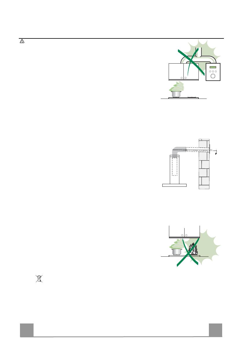
Connecter la hotte à la sortie d’air aspiré à l’aide d’une tuyauterie d’un diamètre égal ou supérieur à 120 mm. Le
parcours de la tuyauterie doit être le plus court possible.
Ne pas connecter la hotte à des conduites d’évacuation de fumées issues d’une combustion tel que (Chau-
dière, cheminée, etc…).
Si vous utilisez des appareils qui ne fonctionnent pas à l’électricité dans la pièce ou est installée la hotte (par
exemple: des appareils fonctionnant au gaz), vous devez prévoir une aération suffisante du milieu. Si la cuisine
en est dépourvue, pratiquez une ouverture qui communique avec l’extérieur pour garantir l’infiltration de l’air pur.
Pour un emploi correct et sans risque, la dépression maximum dans la pièce ne doit pas dépasser 0,04 mbar.
En cas d’endommagement du cordon d’alimentation, faites-le remplacer par le constructeur ou par le service
après-vente, afin de prévenir tout risque.
Si les instructions de montage pour la plaque de cuisson au gaz spécifient une plus grande distance indiquée ci-
dessus, cela doit être pris en compte. Règlement concernant l'évacuation d'air doivent être remplies..
UTILISATION
La hotte a été conçue exclusivement pour l’usage domestique, dans le but d’éliminer les odeurs de la cuisine.
Ne jamais utiliser abusivement la hotte.
Ne pas laisser les flammes libres à forte intensité quand la hotte est en service.
Toujours régler les flammes de manière à éviter toute sortie latérale de ces dernières par rapport au fond des
marmites.
Contrôler les friteuses lors de l’utilisation car l’huile surchauffée pourrait s’enflammer.
Ne pas préparer d’aliments flambés sous la hotte de cuisine : risque d’incendie
Cet appareil ne doit pas être utilisé par des personnes (y compris les enfants) ayant des capacités psychiques,
sensorielles ou mentales réduites, ni par des personnes n’ayant pas l’expérience et la connaissance de ce type
d’appareils, à moins d'être sous le contrôle et la formation de personnes responsables de leur sécurité.
Les enfants doivent être surveillés pour s'assurer qu'ils ne jouent pas avec l'appareil.
• « ATTENTION : Les parties accessibles peuvent devenir très chaudes si utilisées avec des appareils de cuis-
son. »
ENTRETIEN
Avant de procéder à toute opération d’entretien, débrancher la hotte en retirant la fiche ou en actionnant
l’interrupteur général.
Effectuer un entretien scrupuleux et en temps dû des Filtres, à la cadence conseillée (Risque d’incendie).
Pour le nettoyage des surfaces de la hotte, il suffit d’utiliser un chiffon humide et détersif liquide neutre.
Le symbole sur le produit ou son emballage indique que ce produit ne peut être traité comme déchet
ménager. Il doit plutôt être remis au point de ramassage concerné, se chargeant du recyclage du matériel
électrique et électronique. En vous assurant que ce produit est éliminé correctement, vous favorisez la pré-
vention des conséquences négatives pour l’environnement et la santé humaine qui, sinon, seraient le résultat
d’un traitement inapproprié des déchets de ce produit. Pour obtenir plus de détails sur le recyclage de ce
produit, veuillez prendre contact avec le bureau municipal de votre région, votre service d’élimination des
déchets ménagers ou le magasin où vous avez acheté le produit.
FR
2
20
CARACTERISTIQUES
Encombrement
524-700
288
258
498-678
323
150
100
Composants
Réf. Q.té Composants de Produit
1 1 Corps Hotte équipé de: Commandes, Lumière, Groupe
Ventilateur, Filtres
8 1 Grille en Direction Sortie Air
9 1 Flasque de Réduction ø 150-120 mm
10 1 Buse avec clapet ø 150 mm
Réf. Q.té Composants pour l ’installation
12a 8 Vis
12e 2 Vis 2,9 x 9,5
Q.té Documentation
1 Manuel d’instructions
10
9
8
12e
12a
1
  • Page 1 1
  • Page 2 2
  • Page 3 3
  • Page 4 4
  • Page 5 5
  • Page 6 6
  • Page 7 7
  • Page 8 8
  • Page 9 9
  • Page 10 10
  • Page 11 11
  • Page 12 12
  • Page 13 13
  • Page 14 14
  • Page 15 15
  • Page 16 16
  • Page 17 17
  • Page 18 18
  • Page 19 19
  • Page 20 20
  • Page 21 21
  • Page 22 22
  • Page 23 23
  • Page 24 24
  • Page 25 25
  • Page 26 26
  • Page 27 27
  • Page 28 28
  • Page 29 29
  • Page 30 30
  • Page 31 31
  • Page 32 32
  • Page 33 33
  • Page 34 34
  • Page 35 35
  • Page 36 36

AIRLUX AHG770IX Manuale del proprietario

Categoria
Cappe da cucina
Tipo
Manuale del proprietario
Questo manuale è adatto anche per