Vimar 46916.001 Manuale utente

Tipo
Manuale utente

Questo manuale è adatto anche per

Manuale utente
User Manual
46916.001
Tastiera RS485 per telecamera PTZ e gestione DVR
RS485 Keyboard for PTZ camera and DVR management
2
46916.001
IT
Vi ringraziamo per l'acquisto del nostro prodotto. Contattateci per domande in merito all'apparecchio.
Il manuale potrebbe contenere informazioni non completamente corrette in merito alla tecnologia, non adatte alle fun-
zioni del prodotto e al suo funzionamento, oppure errori di stampa. Il contenuto del manuale è sottoposto a modiche
con l'avanzare delle migliorie sul prodotto, come pure le sue funzioni, il suo aggiornamento e le sue procedure. Il con-
tenuto aggiornato sarà aggiunto alla nuova edizione del manuale, senza che ne sia data notica alcuna.
Osservazioni:
Il display LCD si può danneggiare facilmente. Non esporlo a pressione eccessiva, né esporlo al sole per un tempo
prolungato;
Il joystick si può danneggiare facilmente. Se necessita di un intervento di riparazione, imballarlo e spedirlo utilizzando
la confezione originale o di sicurezza;
Questa tastiera deve essere utilizzata all'interno di un determinato intervallo di temperatura e umidità; far riferimento
all'indice tecnico.
Collegare la testiera correttamente, come indicato nel manuale.
Articoli Quantità Nota
Adattatore di corrente CC12V 1 Ingresso: CA100-240V
Connettore a 10 PIN 1
CD in dotazione con il manuale utente 1
Indice
1 Caratteristiche principali ............................................................................................................................................. 1
2 Congurazione e query della tastiera .................................................................................................................... 4
3 Schema elettrico tipico ........................................................................................................................................... 6
4 Speciche tecniche ............................................................................................................................................... 7
1
46916.001
IT
1 Caratteristiche principali
Caratteristiche principali
La tastiera è compatibile con tutte le versioni di registratore video digitale integrato.
Queste tastiere sono in grado di controllare la velocità di cupole e le telecamere sse, grandangolari e a panoramica
verticale (PTZ) o tramite gli DVR.
Sono anche in grado di comandare gli DVR.
Comando
Sostituisce tutte le funzioni del pannello anteriore dell'DVR.
Ogni tipologia di funzionamento è indicata nel display LCD.
Una tastiera è in grado di gestire no a un massimo di 31 DVR.
Comando velocità cupola e PTZ: L'indirizzo della velocità cupola e PTZ è compreso tra 0~254.
Protocollo di comando
Contiene 9 protocolli diversi per PTZ.
È possibile in programmazione scegliere il tipo di protocollo desiderato.
Tastiera che supporta comandi per DVR e PTZ
È possibile controllare più DVR ai quali possono essere collegate no a un massimo di 15 tastiere ausiliarie con codice
d'identità compreso fra 0 e 15
Caratteristiche e funzioni
La essibilità del sistema è migliorata sensibilmente, dato che qualsiasi attrezzatura collegata all'RS485 può essere
impostata in protocolli diversi e a diverse velocità di trasmissione. Poiché tutte le congurazioni possono essere eet-
tuate sul display LCD, non è necessario cercare come cambiare il protocollo.
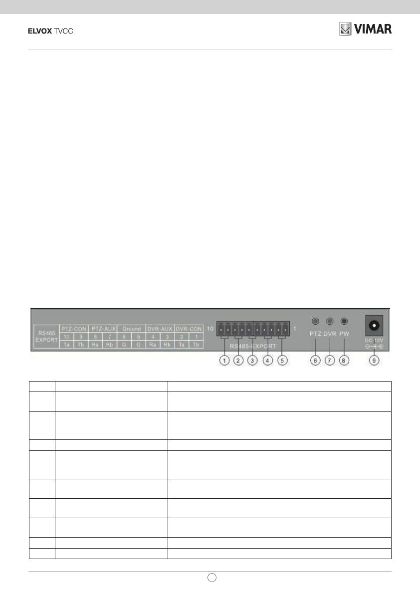
1.1 Introduzione all'interfaccia sul pannello posteriore
No Interfaccia sica Introduzione alla connessione
1 Uscita di controllo PTZ
Collegare ai dispositivi (telecamere/PTZ) RS485 PTZ. Con Ta +
RS485, e Tb RS485-
2
Ingresso della tastiera ausiliaria
per il controllo PTZ
Se necessarie più tastiere, collegare l’ausiliaria, alla principale
secondo quanto indicato: Pin8 (Ra)Tast.Principale con Pin10 Tast.
ausiliaria (Ta) e Pin7 (Rb) Tast. Principale con Pin9 (Tb) tast. Ausiliaria
3 Terra Terminale di Massa del segnale di controllo
4
Ingresso di controllo ausiliario
tastiera di controllo per DVR
Se necessario più tastiere di controllo per DVR collegarle come
indicato: Tast. principale Pin4 (Ra) con Tast. Ausiliaria Pin2(Ta) e Pin3
principale(Rb) con Pin1(Tb) ausiliaria.
5 Uscita di controllo per DVR
Collegare la tastiera principale con i DVR utilizzando Pin2 (Ta) con
DVR KB porta D+, e Pin1 (Tb) con DVR KB porta D-.
6 LED Controllo PTZ
In modalità di controllo PTZ, il led verde lampeggia durante
l’immissione comandi
7 LED Controllo DVR
In modalità di controllo DVR, il led verde lampeggia durante
l’immissione comandi
8 LED di alimentazione LED rosso attivo in modo continuativo quando alimentato
9 Ingresso alimentazione (DC-12V) Alimentazione DC 12V.
2
46916.001
IT
1.2 Introduzione pannello anteriore
Nome pulsante Introduzione della funzione
Addr Seleziona gli indirizzi di PTZ o il codice identità dei registratori integrati
Setup
Tenere premuto per 3 secondi per accedere allo stato di congurazione della tastiera (password
di default: 8888)
Search Tenere premuto per 1 secondo, controllare la congurazione della tastiera: il protocollo PTZ
Shift Commuta la modalità di controllo del registratore integrato o dello PTZ
Nella modalità DVR, commuta l'anteprima di schermate singole da live a playback e viceversa
Nella modalità DVR, commuta l'anteprima di quattro schermate da live a playback e viceversa
Nella modalità DVR, commuta l'anteprima di otto schermate da live a playback e viceversa
Nella modalità DVR, commuta l'anteprima di sedici schermate da live a playback e viceversa
PTZ Digitare nel DVR menu di comando PTZ; nell'interfaccia PTZ per comandare il cursore
dwell Nella modalità DVR, avvia o conclude la funzione dwell (riposo)
Audio Nella modalità DVR, premere AUDIO+NUMBER+ENTER per passare l'audio ai canali pertinenti
Power Alimentazione DVR o
BACKUP Nella modalità DVR, passa al menu di backup
INFO Nella modalità DVR, passa al menu info
+/- Aumenta/diminuisce un determinato valore in tute le modalità
MENU Nella modalità DVR, passa al menu principale
SEARCH Nella modalità DVR, passa al menu ricerca
RECORD Nella modalità DVR, si accede al menu registrazione manuale del DVR
PLAY Nella modalità DVR, si accede al menu riproduzione del DVR
1-9 Numero.: 1, 2, 3, 4, 5, 6, 7, 8, 9 A-Z (26 lettere)
0/10+ Inserire il numero 10 o uno superiore
ENTER Conferma il contenuto appena inserito
ESC Indietro al menu di livello superiore
PRESET Imposta la posizione di PTZ precedentemente impostata
DEL Cancella la posizione di PTZ precedentemente impostata
SHOT Richiama la posizione dei PRESET della PTZ precedentemente impostati
Automatico Imposta lo PTZ su rotazione automatica (dipende dal tipo di PTZ, vedere manuale PTZ)
FOCUS+ /- Imposta la messa a fuoco della lente vicino/lontano
ZOOM+/- Eetto zoom della lente
IRIS+/- Apre/chiude la lente del diaframma
WIPER Relè tergicristallo On/O
Light Relè luce On/O
3
46916.001
IT
Fig Funzionamento Introduzione della funzione
UP
Nella modalità di comando PTZ: comanda i movimenti grandangolare e panoramica
verticale.
Nella modalità di comando DVR: riproduce il le registrato velocemente
DOWN
Nella modalità di comando PTZ: comanda i movimenti grandangolare e panoramica
verticale facendoli spostare sopra.
Nella modalità di comando DVR: riproduce il le registrato lentamente
LEFT
Nella modalità di comando PTZ: comanda i movimenti grandangolare e panoramica
verticale facendoli spostare a sinistra
Nella modalità di comando DVR: comanda il le registrato facendolo andare indietro
RIGHT
Nella modalità di comando PTZ: comanda i movimenti grandangolare e panoramica
verticale facendoli spostare a destra
Nella modalità di comando DVR: comanda il le registrato facendolo andare avanti
RUOTARE A
SINISTRA
Eetto zoom ingrandente della lente
RUOTARE A
SINISTRA
Eetto zoom riducente della lente
1.3 Introduzione comando Joystick
1.4 Introduzione alle indicazioni per il display LCD
Ogni tipologia di funzionamento è indicata e corrispondente nel display LCD. Il display LCD passerà alla modalità di
risparmio energetico (ridurre al minimo la luminosità) in 30 secondi in mancanza di attività.
4
46916.001
IT
2 Congurazione e interrogazione della tastiera
Menu ad albero della tastiera
2.1 Introduzione all'interfaccia sul pannello posteriore
Tenere premuto il tasto SETUP per tre secondi, per accedere allo stato di congurazione della tastiera (pass-
word di default: 8888)
Impostazione PTZ
Indirizzo PTZ
Protocollo corrispondente
Velocità di trasmissione
Sistema parametro
Impostazione password
Ripristinare impostazione predenita
Impostazione suono
Impostazione ID tastiera
Premere il tasto SEARCH
, vericare l'uscita comando, impostazione parametro da tastiera
RICERCA SISTEMA
Nome modello
Numero di serie tastiera
2.2 Verica parametri tastiera:
5
46916.001
IT
Illustrazione congurazione
Di seguito un esempio che spiega come impostare la PTZ: cambiare il protocollo di comunicazione del dome 002 a
PELCO-D, e cambiare la velocità di trasmissione a 4800.
1. Nella modalità di standby (g a), tenere premuto il pulsante “Setup” per 3 secondi, accedere al menu principale (g
b);
2. Inserire la password (g c, password di default: 8888);
3. Premere [Enter], accedere al menu impostazione e spostando il joystick in su o in giù selezionare [PTZ SETUP] o
[SYS SETUP](g d);
4. Selezionare [PTZ SETUP], premere [Enter] per accedere a [PTZ SETUP];
5. Spostare il joystick a sinistra o a destra per scegliere l'indirizzo della PTZ, ad es. 002 (g e, f), quindi premere
[Enter] per accedere al livello successivo di menu (g g);
6. Spostare il joystick in su o in giù per selezionare il protocollo di comunicazione, ad es. PELCO-D (g h);
7. Spostare il joystick a destra per modicare la velocità di trasmissione (g i), quindi selezionare il baud rate spo-
stando in su o in giù (g j);
8. Premere [Enter], quindi premere “ESC” no a che si ritorna alla modalità standby (g a);
9. La congurazione è completata
6
46916.001
IT
3 Schema elettrico tipico
3.1 Comando PTZ
RS485
EXPORT
PTZ-CON PTZ-AUX Ground DVR-AUX DVR-CON
10 9 8 7 6 5 4 3 2 1
Ta Tb Ra Rb G G Ra Rb Ta Tb
RS485-EXPORT
PTZ DVR PW
DC-12V
10 1
RS485
EXPORT
PTZ-CON PTZ-AUX Ground DVR-AUX DVR-CON
10 9 8 7 6 5 4 3 2 1
Ta Tb Ra Rb G G Ra Rb Ta Tb
RS485-EXPORT
PTZ DVR PW
DC-12V
10 1
RS485-EXPORTRS485-EXPORT
A B BA A
.......
TA
RS 485 +
TB
RS 485 -
Verso il DVR
Tastiera ausiliaria
Tastiera Host
Collegare il pin 8 (Ra) della tastiera host
con il pin 10 (Ta) della tastiera ausiliaria
Collegare il pin 7 (Rb) della tastiera host
con il pin 9 (Tb) della tastiera ausiliaria
Collegare il pin 10 (Ta) della
tastiera host con PTZ RS485+
Collegare il pin 9 (Tb) della
tastiera host con PTZ RS485+
Il PTZ o il dome
possono collegare
a cascata no a
un massimo di
128 unità
7
46916.001
IT
3.2 Comando DVR
4 Speciche tecniche
Modello tastiera Descrizione
Supportato 31 DVR
Supportato 128 DVR
Joystick 2D
Interfaccia di comunicazione Porta RS-485
Schermo LCD 122mm* 32mm
Lunghezza max. cavo 1200 m
Temperatura di esercizio -10°C--+55°C
Umidità di esercizio 10%--90%
Alimentazione elettrica CC-12V±10% 50Hz
Potenza di esercizio media 10W
Dimensioni 300mm*180mm*86mm
Peso 2,50kg
RS485
EXPORT
PTZ-CON PTZ-AUX Ground DVR-AUX DVR-CON
10 9 8 7 6 5 4 3 2 1
Ta Tb Ra Rb G G Ra Rb Ta Tb
RS485-EXPORT
PTZ DVR PW
DC-12V
10 1
RS485
EXPORT
PTZ-CON PTZ-AUX Ground DVR-AUX DVR-CON
10 9 8 7 6 5 4 3 2 1
Ta Tb Ra Rb G G Ra Rb Ta Tb
RS485-EXPORT
PTZ DVR PW
DC-12V
10 1
RS485-EXPORTRS485-EXPORT
REC NET PWR
REC NET PWR
.............
TA
RS 485 +
TB
RS 485 -
Tastiera ausiliaria
Tastiera Host
Collegare il pin 3 (Rb) della tastiera host
con il pin 1 (Tb) della tastiera ausiliaria
Collegare il pin 4 (Ra) della tastiera host
con il pin 1 (Ta) della tastiera ausiliaria
Verso il DVR
Collegare il pin 2 (Ta) della tastiera host
con il pin D+ della porta DVR KB (o pin 3
della porta tastiera DVR RJ45)
Collegare il pin 1 (Tb) della tastiera host
con il pin D- della porta DVR KB (o pin 4
della porta tastiera DVR RJ45)
Pin D+ porta DVR KB (o pin 3 della porta
tastiera DVR RJ45)
Pin D- porta DVR KB (o pin 4 della porta
tastiera DVR RJ45)
Il DVR può collegare a cascata no a un
massimo di 31 unità
DVR di rete integrato
8
46916.001
EN
Thanks a lot for purchasing our product. If there is any question, please feel free to contact us.
This manual may have something inaccurate in technology, unsuited with the product’s functions and operations or
the misprints. The manual’s content will change with the enhanced functions of the product, as well as give the regular
advance or renew the product and procedure in this manual. The renewed content will be added in the new edition of
this manual and no separate notice will be given.
Notes:
LCD display can be easily damaged. Please do not press or exposure in sunshine for a long time;
The joystick can be easily damaged. If it needs to be repaired, please wrap and ship it by using original or safety
packaging;
This keyboard should be used in certain range of temperature and humidity, referring the technical index. Please con-
nect the keyboard correctly as this manual requires.
Items Quantity Note
DC12V power adapter 1 Input: AC100-240V
10PIN connector 1
CD with user’s manual 1
Contents
1. Main Features ...........................................................................................................................................................9
2. Conguration and querying of the keyboard ..................................................................................................... ......12
3. Typical wiring diagram ............................................................................................................................................14
4. Technical Specication ...........................................................................................................................................15
9
46916.001
EN
1 Main Features
Main Features
The keyboard is compatible with all versions of integrated digital video recorder. These keyboards can control PTZ and
PTZ either directly, or through the DVRs. Also they can control DVRs as well.
Control
Completely replace the all functions of DVR front panel. Any operation is indicated in LCD display.
One keyboard can manage 31 DVRs maximum.
Control PTZ and PTZ: The PTZ and PTZ address is among 0~254.
Control protocol
Contains 9 dierent protocols for PTZ.
You can choose the type of desired protocol in the programming phase.
Keyboard supporting controls for DVR and PTZ
You can control multiple DVRs which can be connected to up to a maximum of 15 auxiliary keyboards with identity
code between 0 and 15.
Features and functions
The exibility of system is improved wisely as any equipments connect with RS485 can be set in dierent protocols
and baud rates. Due to all the conguration can be done on the LCD display, it is not needed to look for how to change
the protocol.
1.1 Rear panel interface introduction
No Physical interface Connect introduction
1 PTZ control output
Connect to RS485 PTZ devices (cameras/PTZs) With Ta + RS485, and
Tb RS485-
2
Auxiliary keyboard input for the
PTZ control
If you need more than one keyboard, connect the auxiliary one to the
main keyboard as indicated: Pin8 (Ra)Main Keyb. with Pin10 Aux.Keyb.
(Ta) and Pin7 (Rb) Main Keyboard with Pin9 (Tb) aux. Keyboard
3 Ground Ground Terminal of the control signal
4
Auxiliary control input for DVR
keyboard
If you need more DVR control keyboards, connect them as follows: Main
keyb. Pin4 (Ra) with aux. Keyboard Pin2(Ta) and Pin3 main(Rb) with
Pin1(Tb) auxiliary.
5 DVR control output
Connect the main keyboard with the DVR using Pin2 (Ta) with DVR KB
port D+, and Pin1 (Tb) with DVR KB port D-.
6 PTZ control LED In PTZ control mode, the green LED ashes when entering commands
7 DVR control LED In DVR control mode, the green LED ashes when entering commands
8 Power LED Red LED on and steady when powered
9 Power input (DC-12V) 12V DC power supply.
10
46916.001
EN
Button name Function introduction
Addr Choose addresses of PTZ or the device ID of embedded DVRs
Setup Hold for 3 seconds, enter into keyboard conguration state (default password: 8888)
Search Press 1 second, check keyboard Conguration: the PTZ protocol
Shift Switch the control mode of embedded DVR or PTZ
In DVR mode, switch the previews of single screen of live, playback
In DVR mode, switch the previews of four screen of live, playback
In DVR mode, switch the previews of eight screen of live, playback
In DVR mode, switch the previews of sixteen screen of live, playback
PTZ Enter into DVR PTZ control menu; in the PTZ interface to control the cursor
dwell In DVR mode, start or close dwell function
Audio In DVR mode, press AUDIO+NUMBER+ENTER to switch audio to relevant channels
Power Power o DVR
BACKUP In DVR mode, switch to backup menu
INFO In DVR mode, switch to info menu
+/-
Increase/decrease the value under any mode
MENU In DVR mode, show the main menu
SEARCH In DVR mode, switch to show the search menu
RECORD In DVR mode, enter into DVR manual record menu
PLAY In DVR mode, enter into DVR playback menu
1-9
Number.: 1, 2, 3, 4, 5, 6, 7, 8, 9
A-Z (26 letters)
ESC Back to up-level menu
0/10+ Input digital 10 or above
ENTER Conrm currently input content
PRESET Setup the PTZ preset position
DEL Delete the PTZ preset position
SHOT Retrieves the position of the PTZ PRESET previously set
Auto Sets the PTZ auto-rotate (depending on the type of PTZ, see PTZ manual)
FOCUS+ /- Set the lens focus near/far
ZOOM+/- Zoom in/out the lens
IRIS+/- Open /close the lens iris
WIPER On/O the wiper relay
Light On/O the light relay
1.2 Front panel introduction
11
46916.001
EN
Fig Operation Function introduction
UP
In PTZ control mode: control the movement of pan/tilt
In DVR control mode: play record le fast
DOWN
In PTZ control mode: control the pan/tilt to move upon
In DVR control mode: play record le slowly
LEFT
In PTZ control mode: control pan/tilt to move left
In DVR control mode: control record le backward
RIGHT
In PTZ control mode: control pan/tilt to move right
In DVR control mode: control record le forward
ROTATE LEFT Zoom in the lens
ROTATE RIGHT Zoom out the lens
1.3 Joystick control introduction
1.4 LCD display indication introduction
Any operation is indicated and corresponding in LCD display. The LCD will turn into electricity-save mode (Minimum the
lightness) in 30 seconds if there is no any operation.
12
46916.001
EN
2 Conguration and querying of the keyboard
Keyboard menu tree
2.1 Conguration menu tree:
Press and hold SETUP for three seconds, enter into keyboard setup (default password: 8888)
PTZ setup
PTZ address
Corrisponding protocol
Baud rate
System paramenter
Password setup
Restore default setup
Sound setup
Keyboard ID setup
Press SEARCH
, check the control output, parameter setup of the keyboard
SYSTEM SEARCH
Model name
Keyboard serial number
2.2 Inquire Keyboard parameter:
13
46916.001
EN
Conguration illustration
Here is an example to illustrate how to set PTZ: change the communication protocol of dome 002 to PELCO-D, and
change the baud rate to 4800.
1. In the mode of standby (g a), hold the “Setup” button for 3 seconds, login the main menu (g b);
2. Enter the password (g c, default password: 8888);
3. Press [Enter], enter into setup menu, and operate the Joystick up and down to choose [PTZ SETUP] or [SYS
SETUP](g d);
4. Choose [PTZ SETUP], press [Enter] to enter in [PTZ SETUP];
5. Operate the Joystick left and right to choose the address of PTZ, e.g. 002(g e, f(, and then press [Enter] to enter
the next level menu (g g);
6. Operate the Joystick up and down to choose communication protocol, e.g. PELCO-D (g h);
7. Operate the Joystick right to change the baud rate (g i), and then choose the baud rate up and down (g j);
8. Press [Enter], then press “ESC” until back to the standby mode (g a);
9. Conguration is done
14
46916.001
EN
3 Typical wiring diagram
3.1 Control PTZ
RS485
EXPORT
PTZ-CON PTZ-AUX Ground DVR-AUX DVR-CON
10 9 8 7 6 5 4 3 2 1
Ta Tb Ra Rb G G Ra Rb Ta Tb
RS485-EXPORT
PTZ DVR PW
DC-12V
10 1
RS485
EXPORT
PTZ-CON PTZ-AUX Ground DVR-AUX DVR-CON
10 9 8 7 6 5 4 3 2 1
Ta Tb Ra Rb G G Ra Rb Ta Tb
RS485-EXPORT
PTZ DVR PW
DC-12V
10 1
RS485-EXPORTRS485-EXPORT
A B BA A
.......
TA
RS 485 +
TB
RS 485 -
To DVR
Auxiliary keyboard
Host keyboard
Connect host keyboard pin 8 (Ra)
with auxialiary keyboard pin 10 (Ta)
Connect host keyboard pin 7 (Rb)
with auxialiary keyboard pin 9 (Tb)
Connect host keyboard pin
10 (Ta) with PTZ RS485+
Connect host keyboard pin
9 (Tb) with PTZ RS485-
Can cascade
PTZ or speed
dome 128 units
maximum
15
46916.001
EN
RS485
EXPORT
PTZ-CON PTZ-AUX Ground DVR-AUX DVR-CON
10 9 8 7 6 5 4 3 2 1
Ta Tb Ra Rb G G Ra Rb Ta Tb
RS485-EXPORT
PTZ DVR PW
DC-12V
10 1
RS485
EXPORT
PTZ-CON PTZ-AUX Ground DVR-AUX DVR-CON
10 9 8 7 6 5 4 3 2 1
Ta Tb Ra Rb G G Ra Rb Ta Tb
RS485-EXPORT
PTZ DVR PW
DC-12V
10 1
RS485-EXPORTRS485-EXPORT
REC NET PWR
REC NET PWR
.............
TA
RS 485 +
TB
RS 485 -
3.2 Control DVR
4 Technical Specication
Keyboard model Description
Supported 31 DVR
Supported 128 DVR
Joystick 2D
Communication interface RS-485 port
LCD screen 122mm* 32mm
Maximum cable length 1200 m
Working temperature -10°C-- +55°C
Working humidity 10%--90%
Power supply DC-12V±10% 50Hz
Average operation power 10W
Size 300mm*180mm*86mm
Weight 2.50kg
To DVR
Connect host keyboard pin 2 (Ta) with
DVR KB port pin D+ (or DVR RJ45 key-
board port pin 3)
Connetc pin 1 (Tb) with DVR KB port pin
D- (or DVR RJ45 keybuard port pin 4)
DVR KB port pin D+ (or DVR RJ45
keyboard port pin 3)
Can cascade DVR 31 units maximum
Auxiliary keyboard
Host keyboard
Connect host keyboard pin 4 (Ra)
with auxialiary keyboard pin 2 (Ta)
Connect host keyboard pin 3 (Rb)
with auxialiary keyboard pin 1 (Tb)
Embedded Net DVR
Embedded Net DVR
DVR KB port pin D+ (or DVR RJ45
keyboard port pin 4)
16
46916.001
EN
17
46916.001
EN
Viale Vicenza, 14
36063 Marostica VI - Italy
www.vimar.com
S6I.46916.001 02 1709
  • Page 1 1
  • Page 2 2
  • Page 3 3
  • Page 4 4
  • Page 5 5
  • Page 6 6
  • Page 7 7
  • Page 8 8
  • Page 9 9
  • Page 10 10
  • Page 11 11
  • Page 12 12
  • Page 13 13
  • Page 14 14
  • Page 15 15
  • Page 16 16
  • Page 17 17
  • Page 18 18
  • Page 19 19
  • Page 20 20

Vimar 46916.001 Manuale utente

Tipo
Manuale utente
Questo manuale è adatto anche per